|
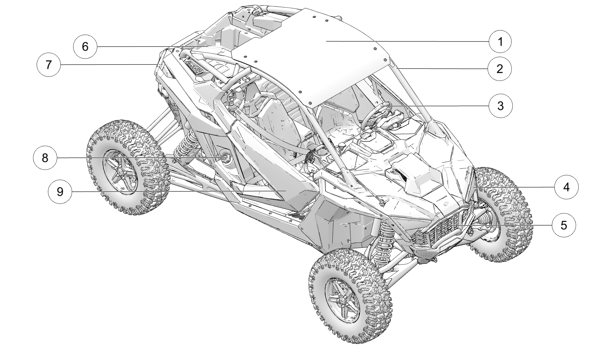
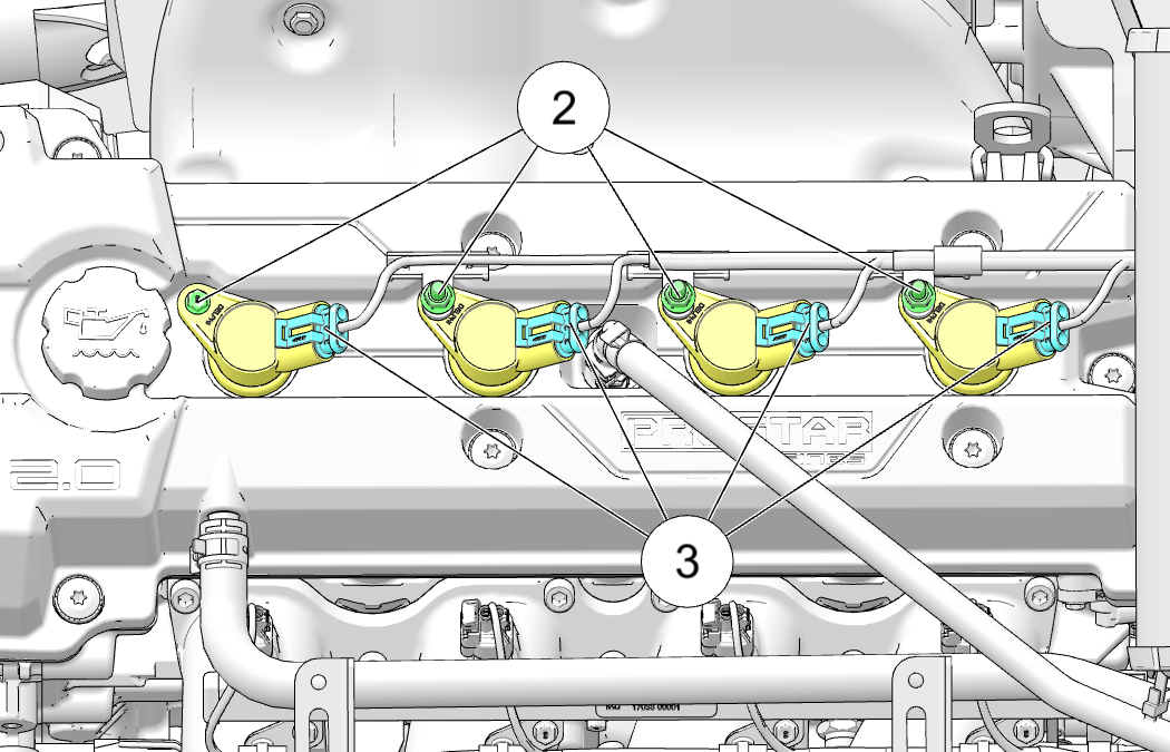
Engine Control Module
|
|
Manifold Absolute Pressure/Barometric Pressure Sensor Circuit
Low
|
102
|
4
|
|
Accelerator Position 2 Voltage Too Low
|
29
|
4
|
|
System Voltage Low
|
168
|
4
|
|
Gear Shift Position Circuit "A" Low
|
523
|
4
|
|
Engine Coolant Temperature Sensor 1 Circuit High
|
110
|
3
|
|
Engine Temperature Sensor Engine Overheat Shutdown
|
110
|
0
|
|
Engine Coolant Temperature Sensor 1 Circuit Low
|
110
|
4
|
|
Crankshaft Position Sensor "A" Circuit
|
636
|
8
|
|
Accelerator Position 2 Voltage Too High
|
29
|
3
|
|
Barometric Pressure Sensor "A" Circuit Low
|
108
|
4
|
|
Engine Coolant Over Temperature Condition
|
110
|
16
|
|
Camshaft Position Sensor "A" Circuit Bank 1 or Single Sensor
|
637
|
8
|
|
Engine Coolant Temperature Sensor 1 Circuit Intermittent/Erratic
|
110
|
10
|
|
Manifold Absolute Pressure/Barometric Pressure Sensor Circuit
High
|
102
|
3
|
|
System Voltage High
|
168
|
3
|
|
Intake Air Temperature Sensor 1 Circuit Intermittent Bank
1
|
105
|
10
|
|
Fuel Level Sensor "A" Circuit Low
|
96
|
4
|
|
Throttle/Pedal Position Sensor/Switch "A" Circuit High
|
51
|
3
|
|
Throttle/Pedal Position Sensor/Switch "C" Circuit Low
|
91
|
4
|
|
Fuel Level Sensor "A" Circuit High
|
96
|
3
|
|
Barometric Pressure Sensor "A" Circuit High
|
108
|
3
|
|
Vehicle Speed Sensor "A" Circuit Intermittent/Erratic/High
|
84
|
2
|
|
Intake Air Temperature Sensor 1 Circuit High Bank 1
|
105
|
3
|
|
Crankshaft Position Sensor "A" Circuit Intermittent
|
636
|
2
|
|
Engine Speed Error in Engine Speed Computation
|
190
|
31
|
|
Intake Air Temperature Sensor 1 Circuit Low Bank 1
|
105
|
4
|
|
Throttle/Pedal Position Sensor/Switch "C" Circuit High
|
91
|
3
|
|
Throttle/Pedal Position Sensor/Switch "A" Circuit Low
|
51
|
4
|
|
Fan Relay Driver Circuit Driver Circuit Short to B+
|
1071
|
3
|
|
Ignition Coil "A" Primary Control Circuit High
|
1268
|
3
|
|
Fuel Pump Primary Circuit
|
1347
|
5
|
|
HO2S Heater Control Circuit High Bank 1 Sensor 1
|
520209
|
3
|
|
Cylinder 1 Injector "A" Circuit High
|
651
|
3
|
|
Low Speed CAN Communication Bus
|
516125
|
2
|
|
Injector 3 Driver Circuit Grounded
|
653
|
4
|
|
Knock/Combustion Vibration Sensor "A" Circuit Range/Performance
|
731
|
2
|
|
Starter Relay "A" Circuit Low
|
677
|
4
|
|
Ignition Coil "B" Primary Control Circuit High
|
1269
|
3
|
|
Cylinder 2 Injector "A" Circuit High
|
652
|
3
|
|
ECU Output Supply Voltage 2 Voltage Above Warning Level
|
3598
|
16
|
|
Cylinder 3 Injector "A" Circuit High
|
653
|
3
|
|
Ignition Coil "B" Primary Control Circuit Low
|
1269
|
4
|
|
Cylinder 4 Injector "A" Circuit High
|
654
|
3
|
|
Fuel Pump Secondary Circuit Low
|
1347
|
4
|
|
Fuel Pump Secondary Circuit High
|
1347
|
3
|
|
Cylinder 1 Injector "A" Circuit Low
|
651
|
4
|
|
Cylinder 2 Injector "A" Circuit
|
652
|
5
|
|
Cylinder 4 Injector "B" Circuit Low
|
654
|
4
|
|
O2 Sensor Circuit Low Voltage Bank 1 Sensor 1
|
3056
|
4
|
|
HO2S Heater Control Circuit Low Bank 1 Sensor 1
|
520209
|
4
|
|
EVAP System Purge Control Valve "A" Circuit
|
520202
|
3
|
|
Chassis Relay Driver Circuit Grounded
|
520208
|
4
|
|
All Wheel Drive Control Circuit Driver Circuit Grounded
|
520207
|
4
|
|
Chassis Relay Driver Circuit Open/Grounded
|
520208
|
5
|
|
HO2S Heater Control Circuit Bank 1 Sensor 1
|
520209
|
5
|
|
Ignition Coil Primary Driver 3 Driver Circuit Grounded
|
1270
|
4
|
|
Throttle/Pedal Position Sensor/Switch "B" Circuit High
|
520198
|
3
|
|
Misfire Detected - Fueling Disabled
|
65590
|
31
|
|
ECU Output Supply Voltage 2 Voltage Below Warning Level
|
3598
|
18
|
|
EVAP System Purge Control Valve "A" Circuit Open
|
520202
|
5
|
|
Cylinder 1 Misfire Detected
|
65591
|
7
|
|
Cylinder 3 Misfire Detected
|
65593
|
7
|
|
O2 Sensor Circuit Bank 1 Sensor 1
|
3056
|
5
|
|
Random/Multiple Cylinder Misfire Detected
|
65599
|
7
|
|
Cylinder 2 Injector "A" Circuit Low
|
652
|
4
|
|
Single Cylinder Misfire (Cylinder not Specified)
|
65590
|
7
|
|
Cylinder 4 Injector "A" Circuit Low
|
654
|
5
|
|
Fan Relay Driver Circuit Driver Circuit Grounded
|
1071
|
4
|
|
Ignition Coil "A" Primary Control Circuit Low
|
1268
|
4
|
|
Powertrain Relay Stuck
|
66013
|
7
|
|
Fan Relay Driver Circuit Driver Circuit Open/Grounded
|
1071
|
5
|
|
Cylinder 1 Injector "A" Circuit
|
651
|
5
|
|
Ignition Coil Primary Driver 3 Driver Circuit Short to B+
|
1270
|
3
|
|
Cylinder 4 Misfire Detected
|
65594
|
7
|
|
O2 Sensor Circuit High Voltage Bank 1 Sensor 1
|
3056
|
3
|
|
ECU Output Supply Voltage 1 Voltage Above Warning Level
|
3597
|
16
|
|
All Wheel Drive Control Circuit Driver Circuit Short to
B+
|
520207
|
3
|
|
Accelerator Sensor Synchronicity Fault - Sensor Difference
Exceeds Limit Condition Exists
|
520308
|
31
|
|
Throttle Body Control - Limp Home Position Check Failed
Condition Exists
|
520280
|
31
|
|
Throttle Position Sensor Neither Position Sensor Passed
Test
|
520276
|
12
|
|
Function Monitoring MoFTrq Comparison Error
|
520385
|
31
|
|
Throttle Body Control - Mechanical Stop Adptation Failure
Condition Exists
|
520281
|
31
|
|
RBA Monitoring Error Memory Read/Write
|
520383
|
31
|
|
ECU ADC Fault - No Load Condition Exists
|
520306
|
31
|
|
EVAP System Purge Control Valve "A" Circuit Shorted
|
520202
|
4
|
|
Chassis Relay Driver Circuit Short to B+
|
520208
|
3
|
|
ETC Accelerator Position Sensor Outputs 1 & 2 Correlation.
Correlation Fault
|
65613
|
2
|
|
Cylinder 3 Injector "A" Circuit Low
|
653
|
5
|
|
All Wheel Drive Control Circuit Driver Circuit Open/Grounded
|
520207
|
5
|
|
ECU Output Supply Voltage 1 Voltage Below Warning Level
|
3597
|
18
|
|
Cylinder 2 Misfire Detected
|
65592
|
7
|
|
Ignition Coil Primary Driver 4 Driver Circuit Short to B+
|
1271
|
3
|
|
Throttle/Pedal Position Sensor/Switch "B" Circuit Low
|
520198
|
4
|
|
EMM Alarm FCCU Hardware Module
|
520248
|
31
|
|
RBA Monitoring Error T15
|
520384
|
31
|
|
Monitoring Error Starter Release
|
520390
|
31
|
|
ECU ADC Fault - Voltage Condition Exists
|
520307
|
31
|
|
ICO Request MoCSOP Module
|
520386
|
31
|
|
ECU Monitoring of Injection Cut Off (Level 2) Condition
Exists
|
520289
|
31
|
|
Throttle Body Control - Power Stage Not Plausible
|
520277
|
2
|
|
Knock Sensor Positive Line Voltage Too High
|
520331
|
3
|
|
Knock Sensor Positive Line Voltage Too Low
|
520331
|
4
|
|
Brake Switch (1 or 2 Indeterminable) Brake Switch Correlation
Fault
|
520285
|
2
|
|
Intake Air System Leak Bank 1
|
520338
|
31
|
|
Drive Mode Select Switch Signal Fault
|
524067
|
2
|
|
Knock Sensor Negative Line Voltage Too High
|
520332
|
3
|
|
Throttle Body Control - Power Stage Minimum
|
520277
|
4
|
|
Monitoring Error Post Build
|
520387
|
31
|
|
ECU Monitoring Error (Level 3) Condition Exists
|
520287
|
31
|
|
Throttle Body Control - Power Stage Signal Error
|
520277
|
8
|
|
High Speed CAN Communication Bus
|
521092
|
2
|
|
Drive Mode Select Switch Voltage Too High
|
524067
|
3
|
|
Accelerator Position/Brake Position Interaction Condition
Exists
|
520275
|
31
|
|
System Too Lean Off Idle Bank 1
|
520344
|
17
|
|
Throttle Body Control - Power Stage Maximum
|
520277
|
3
|
|
Throttle Body Control - Position Deviation Fault Condition
Exists
|
520284
|
31
|
|
ECU Monitoring of Injection Cut Off (Level 1) Condition
Exists
|
520288
|
31
|
|
Knock Sensor Negative Line Voltage Too Low
|
520332
|
4
|
|
Throttle Body Control - Adaption Aborted Condition Exists
|
520279
|
31
|
|
System Too Rich Off Idle Bank 1
|
520344
|
15
|
|
Throttle Body Control Maximum
|
520283
|
3
|
|
Drive Mode Select Switch Voltage Too Low
|
524067
|
4
|
|
Monitoring Error ECU Ignition Check
|
520388
|
31
|
|
Throttle Body Control - Return Spring Check Failed Condition
Exists
|
520278
|
31
|
|
Function Monitoring MoFAir Group
|
520249
|
31
|
|
RBA Monitoring Error Keep Alive
|
520382
|
31
|
|
Throttle Position Sensor Position Sensor Correlation Fault
|
520276
|
2
|
|
Torque Request CAN Message
|
65557
|
22
|
|
Front Wheel Back Drive (Active Descent System) Driver Circuit
Open/Grounded
|
520203
|
5
|
|
Front Wheel Back Drive (Active Descent System) Driver Circuit
Short to B+
|
520203
|
3
|
|
Gear Sensor Signal Abnormal Update Rate
|
523
|
9
|
|
Lost Communication With Front Controls/Display Interface
Module
|
524067
|
9
|
|
Brake Lamp Open Circuit
|
520320
|
5
|
|
Brake Lamp Shorted to Ground
|
520320
|
4
|
|
Front Wheel Back Drive (Active Descent System) Driver Circuit
Grounded
|
520203
|
4
|
|
ESC 65312 checksum failure
|
65557
|
23
|
|
Brake Lamp Shorted to Battery
|
520320
|
3
|
|
System Too Lean Bank 2
|
520205
|
17
|
|
Coolant Thermostat (Coolant Temperature Below Thermostat
Regulating Temperature)
|
110
|
17
|
|
Engine Coolant Temperature Sensor 1 Circuit Intermittent/Erratic
|
110
|
10
|
|
Rear Differential Output Driver Circuit Open/Grounded
|
746
|
5
|
|
System Too Lean Bank 1
|
520204
|
17
|
|
Rear Differential Output Driver Circuit Grounded
|
746
|
4
|
|
Knock/Combustion Vibration Sensor "A" Circuit Range/Performance
|
731
|
2
|
|
Rear Differential Output Driver Circuit Short to B+
|
746
|
3
|
|
System Power Voltage Below Critical Level
|
168
|
1
|
|
Engine Temperature Sensor Temperature above normal range
|
110
|
15
|
|
System Too Rich Bank 2
|
520205
|
15
|
|
System Too Rich Bank 1
|
520204
|
15
|
|
Manifold Absolute Pressure/Barometric Pressure Sensor Circuit
Range/Performance
|
102
|
2
|
|
Manifold absolute pressure sensor out of range low
|
102
|
17
|
|
Manifold absolute pressure sensor out of range high
|
102
|
15
|
|
Charge Air Cooler Cooling Fan Control Circuit Low
|
524280
|
4
|
|
Charge Air Cooler Cooling Fan Control Circuit High
|
524280
|
3
|
|
Gear Shift Position Circuit "A" High
|
523
|
3
|
|
O2 Sensor Signal Biased/Stuck Lean Bank 2 Sensor 1
|
3057
|
17
|
|
Ambient Air Temperature Sensor Circuit "A" High
|
171
|
3
|
|
AC Condenser Fan Relay Open
|
520624
|
5
|
|
Fuel Level Sensor "A" Circuit Range/Performance
|
96
|
2
|
|
O2 Sensor Circuit High Voltage Bank 2 Sensor 1
|
3057
|
3
|
|
AC Condenser Fan Relay Low
|
520624
|
4
|
|
Fuel Level Signal Below Normal Operating Range
|
96
|
18
|
|
O2 Sensor Signal Circuit Shorted to Heater Circuit Bank
1 Sensor 1
|
3056
|
2
|
|
O2 Sensor Signal Biased/Stuck Lean Bank 1 Sensor 1
|
3056
|
17
|
|
O2 Sensor Heater Circuit Bank 1 Sensor 1
|
520209
|
2
|
|
Ambient Air Temperature Sensor Circuit "A" Range/Performance
|
171
|
2
|
|
Crankshaft Position Sensor "A" Circuit Intermittent
|
636
|
2
|
|
O2 Sensor Circuit Low Voltage Bank 2 Sensor 1
|
3057
|
4
|
|
O2 Sensor Circuit Slow Response Bank 1 Sensor 1
|
3056
|
12
|
|
Fuel Level Signal Above Normal Operating Range
|
96
|
16
|
|
System Too Lean Off Idle Bank 2
|
520345
|
17
|
|
Gear Shift Position Circuit "A" Range/Performance
|
523
|
11
|
|
System Too Rich Off Idle Bank 2
|
520345
|
15
|
|
O2 Sensor Signal Biased/Stuck Rich Bank 2 Sensor 1
|
3057
|
15
|
|
O2 Sensor Signal Biased/Stuck Rich Bank 1 Sensor 1
|
3056
|
15
|
|
AC Condenser Fan Relay High
|
520624
|
3
|
|
Charge Air Cooler Cooling Fan Control Circuit/Open
|
524280
|
5
|
|
Ambient Air Temperature Sensor Circuit "A" Low
|
171
|
4
|
|
O2 Sensor Signal Circuit Shorted to Heater Circuit Bank
2 Sensor 1
|
3057
|
2
|
|
O2 Sensor Circuit Slow Response Bank 2 Sensor 1
|
3057
|
12
|
|
Charge Air Cooler Cooling Fan 2 Control Circuit Low
|
524281
|
4
|
|
Charge Air Cooler Cooling Fan 2 Control Circuit High
|
524281
|
3
|
|
Ignition Coil "A" Primary Control Circuit High
|
1268
|
3
|
|
Ignition Coil Primary Driver 3 Driver Circuit Grounded
|
1270
|
4
|
|
Ignition Coil "A" Primary Control Circuit Low
|
1268
|
4
|
|
O2 Sensor Heater Circuit Bank 2 Sensor 1
|
520210
|
2
|
|
Charge Air Cooler Cooling Fan 2 Control Circuit/Open
|
524281
|
5
|
|
Ignition Coil "B" Primary Control Circuit Low
|
1269
|
4
|
|
O2 Sensor Circuit Bank 2 Sensor 1
|
3057
|
5
|
|
Intake Air Temperature Too High
|
105
|
15
|
|
Ignition Coil "B" Primary Control Circuit High
|
1269
|
3
|
|
HO2S Heater Control Circuit High Bank 2 Sensor 1
|
520210
|
3
|
|
HO2S Heater Control Circuit Bank 2 Sensor 1
|
520210
|
5
|
|
HO2S Heater Control Circuit Low Bank 2 Sensor 1
|
520210
|
4
|
|
Ignition Coil Primary Driver 3 Driver Circuit Short to B+
|
1270
|
3
|
|
Ignition Coil Primary Driver 4 Driver Circuit Short to B+
|
1271
|
3
|
|
Knock Sensor 2 Negative Line Short To GND
|
520126
|
4
|
|
Fan 2 Control Circuit Low
|
1557
|
4
|
|
Fan 2 Control Circuit High
|
1557
|
3
|
|
Knock Sensor 2 Negative Line Short To BAT
|
520126
|
3
|
|
Fan 2 Control Circuit
|
1557
|
5
|
|
Knock Sensor 2 Positive Line Short To BAT
|
520127
|
3
|
|
Transmission Mode Switch "A" Circuit
|
520467
|
31
|
|
Knock Sensor 2 Positive Line Short To GND
|
520127
|
4
|
|
System Too Rich at Idle Bank 1
|
520342
|
15
|
|
ECU Output Supply Voltage 2 Voltage Above Critical Level
|
3598
|
0
|
|
Starter Relay "A" Circuit
|
677
|
5
|
|
Throttle Body Control - Return Spring Check Failed Condition
Exists
|
520278
|
31
|
|
System Too Lean at Idle Bank 2
|
520343
|
17
|
|
Transmission Mode Switch "B" Circuit
|
520468
|
31
|
|
ECU Output Supply Voltage 1 Voltage Too Low
|
3597
|
4
|
|
System Too Rich at Idle Bank 2
|
520343
|
15
|
|
Turbocharger/Supercharger Boost Sensor "A" Circuit Low
|
1127
|
4
|
|
Trunk brake lamp short to GND
|
520172
|
4
|
|
Gear Shift Position Circuit "A"
|
523
|
2
|
|
ECU Output Supply Voltage 2 Voltage Too Low
|
3598
|
4
|
|
ECU Memory EEPROM Read/Write Failure
|
628
|
12
|
|
Trunk brake lamp short to BAT
|
520172
|
3
|
|
Turbocharger/Supercharger Boost Sensor "A" Circuit High
|
1127
|
3
|
|
Reverse Override Switch Stuck
|
524145
|
31
|
|
System Too Lean at Idle Bank 1
|
520342
|
17
|
|
ECU Output Supply Voltage 1 Voltage Above Critical Level
|
3597
|
0
|
|
Throttle Body Control - Repeated Adaptation Failed Condition
Exists
|
520282
|
31
|
|
Starter Relay "A" Circuit High
|
677
|
3
|
|
EPS Module
|
|
Software initialization error
|
520229
|
31
|
|
ECU Memory EEPROM Read/Write Failure
|
628
|
12
|
|
Steering motor current uncontrolled
|
520222
|
6
|
|
Excessive EPS internal temperature
|
520225
|
0
|
|
System Power Voltage Too High
|
168
|
3
|
|
Steering angle sensor out of range
|
1807
|
31
|
|
EPS internal temperature warning
|
520225
|
16
|
|
External fault, engine speed reception
|
524000
|
19
|
|
Steering angle sensor not calibrated
|
1807
|
13
|
|
System Power Voltage Too Low
|
168
|
4
|
|
EPAS Power Save Condition Power Save Timeout
|
520231
|
31
|
|
Motor driver IC error
|
520448
|
12
|
|
External fault, vehicle speed reception
|
84
|
19
|
|
Steering Over Current Shut Down Current Above Normal or
Grounded
|
520221
|
6
|
|
Position Encoder Error Position Encoder Error
|
520228
|
11
|
|
Internal fault, thermistor malfunction
|
520225
|
12
|
|
Motor relay error
|
520552
|
12
|
|
CPU error
|
65580
|
12
|
|
Steering angle sensor out of range
|
1807
|
12
|
|
EPS motor drive voltage out of range
|
520672
|
31
|
|
Power relay error
|
520672
|
12
|
|
Power supply IC error
|
524086
|
12
|
|
Steering Torque Full Failure
|
520224
|
12
|
|
EPAS CAN Communications Transmit Error No TX Message for
x Seconds
|
520227
|
2
|
|
EPS Calibration CRC error
|
630
|
23
|
|
Steering Torque Partial Failure
|
520223
|
12
|
|
Lost Communication With ECM/PCM "A"
|
520226
|
2
|
|
Suspension Control Module
|
|
Suspension Control Module Acceleration Sensor Measurement
Out of Range
|
516115
|
12
|
|
Engine Speed Data Invalid
|
524000
|
2
|
|
Absolute Shock Current Error - Rebound Rear Right
|
516314
|
11
|
|
Steering Angle and Velocity Signal Not Received from Power
Steering Module
|
516117
|
9
|
|
Shock Valve Supply Relay Driver Shorted to Low Source or
Open Circuit
|
516110
|
4
|
|
Suspension Mode Switch Input Voltage in Invalid Range
|
516098
|
2
|
|
Gear Position Signal Not Received from Engine Control Module
|
516121
|
9
|
|
Valve Driver Shorted Low or Open Circuit - Compression Front
Left
|
516106
|
4
|
|
System Voltage below minimum - most severe level
|
516126
|
1
|
|
Absolute Shock Current Error - Compression Rear Right
|
516114
|
11
|
|
Valve Driver Shorted High - Compression Front Right
|
516107
|
3
|
|
Suspension Control Module CAN Communication Transmit Error
|
516125
|
11
|
|
Absolute Shock Current Error - Rebound Rear Left
|
516313
|
11
|
|
Absolute Shock Current Error - Compression Front Right
|
516112
|
11
|
|
Suspension Control Module Temperature Below Normal
|
516115
|
17
|
|
Suspension Mode Switch Input - Voltage below minimum threshold
|
516098
|
4
|
|
Requested Power Steering Mode does not Match Active Power
Steering Mode
|
524116
|
31
|
|
Valve Driver Shorted Low or Open Circuit - Compression Front
Right
|
516107
|
4
|
|
Valve Driver Shorted Low or Open Circuit - Rebound Front
Right
|
523991
|
4
|
|
Absolute Shock Current Error - Compression Rear Left
|
516113
|
11
|
|
Suspension Control Module Temperature Above Normal
|
516115
|
15
|
|
Vehicle Speed Data Implausible Based On Slew Rate
|
516123
|
21
|
|
Vehicle Speed Signal Not Received from Engine Control Module
|
516120
|
9
|
|
Valve Driver Shorted High - Compression Rear Left
|
516108
|
3
|
|
Operator Button 51 [Mode Up] - Data Erratic, Intermittent
Or Incorrect
|
523963
|
2
|
|
Valve Driver Shorted Low or Open Circuit - Compression Rear
Left
|
516108
|
4
|
|
Brake Switch Status Data Invalid
|
520572
|
2
|
|
Vehicle Speed Data - Implausible - Based on Engine Speed
and Gear
|
516123
|
20
|
|
Steering Alignment Out of Range - Above Normal
|
516122
|
15
|
|
Suspension Control Module Mounting Orientation Error Detected
|
516115
|
2
|
|
System Voltage above maximum - most severe level
|
516126
|
0
|
|
Valve Driver Shorted Low or Open Circuit - Compression Rear
Right
|
516109
|
4
|
|
Valve Driver Shorted High - Compression Rear Right
|
516109
|
3
|
|
Valve Driver Shorted High - Compression Front Left
|
516106
|
3
|
|
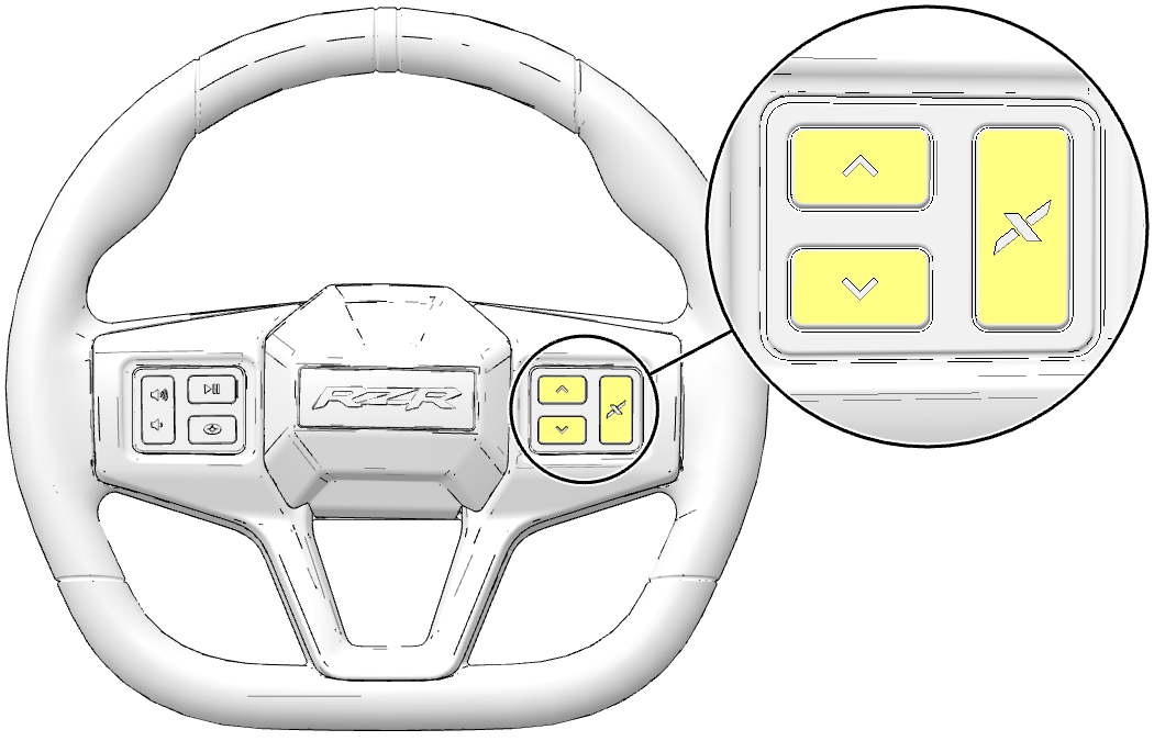
Mode Up/Down and Pucker Button Signal Not Received from
Steering Wheel
|
516183
|
9
|
|
Operator Button 50 [Pucker] - Data Erratic, Intermittent
Or Incorrect
|
523962
|
2
|
|
Valve Driver Shorted Low or Open Circuit - Rebound Rear
Right
|
523993
|
4
|
|
System Voltage below minimum moderately severe level
|
516126
|
18
|
|
Valve Driver Shorted High - Rebound Front Right
|
523991
|
3
|
|
Valve Driver Shorted High - Rebound Rear Right
|
523993
|
3
|
|
Engine Speed Signal Not Received from Engine Control Module
|
516116
|
9
|
|
Valve Driver Shorted High - Rebound Rear Left
|
523992
|
3
|
|
Operator Button 52 [Mode Down] - Data Erratic, Intermittent
Or Incorrect
|
523964
|
2
|
|
System Voltage above maximum - moderately severe level
|
516126
|
16
|
|
Absolute Shock Current Error - Rebound Front Left
|
516311
|
11
|
|
Absolute Shock Current Error - Rebound Front Right
|
516312
|
11
|
|
Engine Torque Demanded Signal Not Received from Engine Control
Module
|
521038
|
9
|
|
Steering Angle Data Invalid
|
524114
|
2
|
|
Vehicle Speed Data Invalid
|
516123
|
2
|
|
Transmission Requested Range Data Invalid
|
162
|
2
|
|
System Voltage Shorted to High Source
|
516126
|
3
|
|
System Voltage Shorted to Low Source or Open Circuit
|
516126
|
4
|
|
Shock Valve Supply Relay Driver Shorted High
|
516110
|
3
|
|
Valve Driver Shorted Low or Open Circuit - Rebound Front
Left
|
523990
|
4
|
|
Steering Alignment Out of Range - Below Normal
|
516122
|
17
|
|
SW Version / HW Version Compatibility - Data Inconsistent
|
516119
|
2
|
|
Suspension Mode Switch Input - Voltage Above Maximum Threshold
|
516098
|
3
|
|
Absolute Shock Current Error - Compression Front Left
|
516111
|
11
|
|
Accelerator Pedal Position Data Invalid
|
520574
|
2
|
|
Valve Driver Shorted High - Rebound Front Left
|
523990
|
3
|
|
Suspension Control Module Internal Error
|
516124
|
12
|
|
Valve Driver Shorted Low or Open Circuit - Rebound Rear
Left
|
523992
|
4
|
|
Accelerator Pedal Position and Brake Switch Signal Not Received
from Engine Control Module
|
516118
|
9
|
|
Steering Wheel Controls
|
|
Left Hand Control Watchdog Reset Root Cause Not Known
|
520191
|
11
|
|
Right Hand Control Watchdog Reset Root Cause Not Known
|
520191
|
11
|
|
Instrument Cluster
|
|
Lost Communication With Power Steering Control Module "A"
|
520230
|
31
|
|
Ride Command Display
|
|
Battery Potential / Power Input 1
|
168
|
1
|