Accessory Installation
Release Ride Command® Screen Bracket and Trim
If not equipped with Ride Command®, trim piece around storage bin still needs to be removed.
-
Remove and keep two push-pin rivets A and two screws B from trim panels.

-
Carefully bend top of trim panel C sides outward. Lift and tilt center console frame D rear ward.
CAUTIONProtect Ride Command® screen with a soft cloth or damage to screen may occur.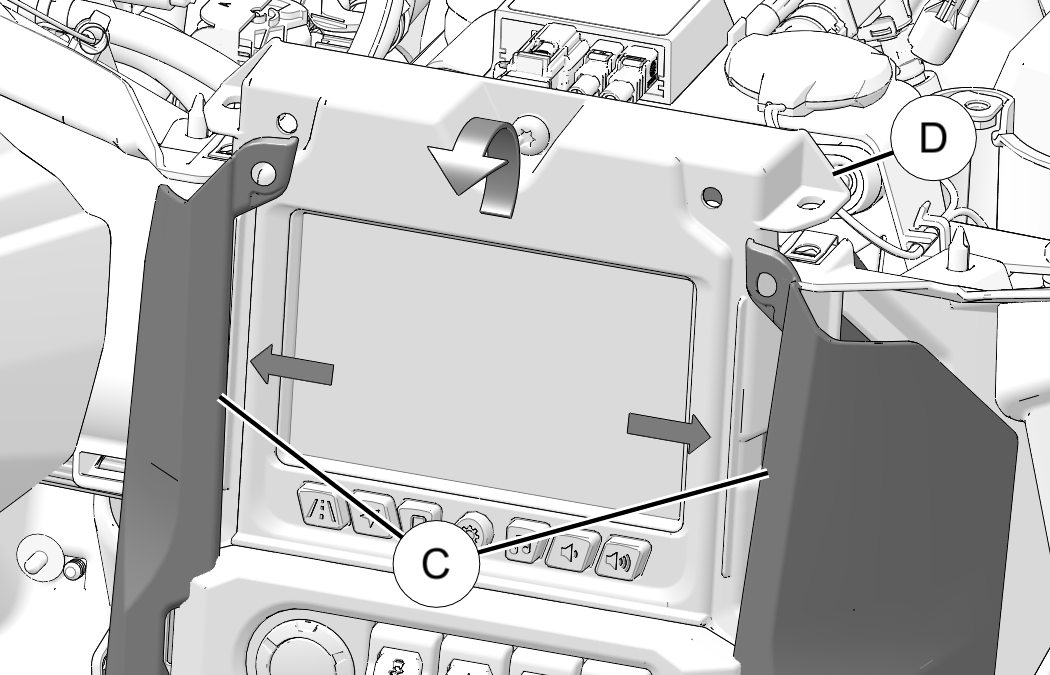
Install Switch (If not equipped)
If already equipped with dash switch skip to next section.
-
Remove and discard blank switch plug A from center console frame.
TIPUse a small tipped tool to push blank out from behind.
-
Insert new switch (PN:4018413, sold separately) into opening with light icon on upper half as shown. Press in until a click is heard.

Install Wiring and Center Console LED Lighting
-
Plug Interior Light switch connector (1A) into interior light switch.

-
Plug Center Console LED lights (1B) into two openings in center console trim. Install straight down to align tabs.

-
Loosely route wiring as shown. Connector (1C) routes to passenger side of vehicle.

Install Passenger Footwell LED Lighting and Chassis Harness Connector
-
Route wiring lead under coolant bottle and plug Chassis Harness Connector (1C) into chassis harness.

-
Plug Passenger Footwell LED lights (1D) into two openings above passenger footwell. Install straight down to align tabs.
NOTICEColor LED has a longer wire and should be installed in outer-most hole.
-
Secure LED harness to vehicle harness with cable tie 2.

Install Driver Footwell LED Lighting
-
Remove and keep four screws A from ECU B.

-
Leave wiring connected and rotate ECU away from mounting bracket.
-
Remove and keep three screws C from fuse block bracket D.

-
Slide fuse block bracket D forward until two holes for LED lights can be seen.

-
Route Driver Footwell LED lights (1D) to two openings above driver footwell. Install straight down to align tabs.
NOTICEColor LED has a longer wire and should be installed in outer-most hole.
-
Slide fuse block bracket D back into place and secure with three screws C. Torque screws to specification.
TORQUEFuse Block Bracket Screw C:
65 in-lbs (7.3 N·m)
-
Set ECU B back into place and secure four retained screws A. Torque screws to specification.
TORQUEECU Mounting Screw A:
15 in-lbs (1.7 N·m)
Reinstall Ride Command® Screen Bracket and Trim
-
Carefully bend top of trim panel C sides outward. Lift and tilt center console frame D into place.
CAUTIONProtect Ride Command® screen with a soft cloth or damage to screen may occur. -
Install two retained push-pin rivets A and two screws B into trim panels. Torque screws to specification.
TORQUERide Command Trim Screw B:
36 in-lbs (4 N·m)