1 Application
Model Year 2020 and newer
Verify accessory fitment at www.polarisslingshot.com.
Model Year 2020 and newer
Verify accessory fitment at www.polarisslingshot.com.
Read these instructions and check to be sure all parts and tools are accounted for. Please retain these installation instructions for future reference and parts ordering information.
When adding accessories, equipment, passengers and luggage to your
vehicle, do not exceed the total weight capacity of the vehicle or
of the front or rear axle (GVWR or GAWR as indicated on the Safety
Compliance Certification label). Ask an authorized dealer for specific
weight information if you need assistance. It is the owner’s
responsibility to use the Polaris Slingshot Accessories website as
a tool for limiting the amount of accessories, based on maximum allowable
vehicle weight requirements. It may be a violation of the Clean Air
Act or the NHTSA regulations to disregard these requirements.
For a complete listing of the accessories that are available for your
vehicle, please contact your authorized dealer or visit the online
store web site:
Web Address (United States): http://www.polaris.com/en-us/slingshot/shop/accessories
.
Only parts for installation of the are included. For complete installation on models not already equipped with interior lighting, the following additional part is required (sold separately):
Interior Light Switch, P/N 4018413

|
Ref |
Qty |
Part Description |
P/N Available Separately |
|---|---|---|---|
| 1 | 1 | Interior Light, LED, Blue (Kit PN 2884805) Interior Light, LED, Red (Kit PN 2884806) Interior Light, LED, Green (Kit PN 2884807) Interior Light, LED, Yellow (Kit PN 2884808) Interior Light, LED, Orange (Kit PN 2884809) |
2414974 2415561 2415562 2415563 2415564 |
| 2 | 1 | Cable Tie | 7080138 |

|
Ref |
Part Description |
Pin Qty |
Connects to |
|---|---|---|---|
| 1A | Interior Lighting Switch Connector | 10 | Interior Light Switch |
| 1B | LED, Center Console | N/A | Center Console Frame |
| 1C | Chassis Harness Connector | 2 | Chassis Harness |
| 1D | LED, Passenger Footwell | N/A | Passenger Footwell Trim |
| 1E | LED, Driver Footwell | N/A | Driver Footwell Trim |
Safety Glasses
Pliers, Push Pin Rivet
Socket Set, Hex Bit, Metric
Socket Set, Torx® Bit
Torque Wrench
Your is exclusively designed for your vehicle. Please read the installation instructions thoroughly before beginning. Installation is easier if the vehicle is clean and free of debris. For your safety, and to ensure a satisfactory installation, perform all installation steps correctly in the sequence shown.
Shift vehicle transmission into NEUTRAL.
Press start/stop button to turn vehicle OFF.
Apply parking brake.
Remove key fob from proximity of vehicle.
Do not grab plastic directly above the hood release lever to open the hood. This may damage the hood.
Make sure parking brake is applied.
Pull hood release lever upward to disengage four hood latches.

Pull upwards on hood underside, above LED lamp, using two hands.

Pull hood upward and forward, rotating hood to a vertical position.

Remove and keep two mirror mounting screws.

Remove and carefully set aside mirror assembly.
Repeat for opposite side mirror.
Remove and keep three fasteners A from base of windshield B.

If equipped, remove and keep screw, washer and O-ring from center windshield mount.

Remove windshield and carefully set aside.
Remove and keep upper dash painted panels by lifting from front edges to release clips.

Remove and keep two screws A and two push-pin rivets B from side trim panel C.

Remove side trim panel C and carefully set aside.

Remove and keep eight screws A from upper dash panel.

If equipped, disconnect dash tweeter speakers from main vehicle harness.
Lift front edge of upper dash panel to release clips. Lift off upper dash panel and carefully set aside.

If not equipped with Ride Command®, trim piece around storage bin still needs to be removed.
Remove and keep two push-pin rivets A and two screws B from trim panels.

Carefully bend top of trim panel C sides outward. Lift and tilt center console frame D rear ward.
If already equipped with dash switch skip to next section.
Remove and discard blank switch plug A from center console frame.

Insert new switch (PN:4018413, sold separately) into opening with light icon on upper half as shown. Press in until a click is heard.

Plug Interior Light switch connector (1A) into interior light switch.

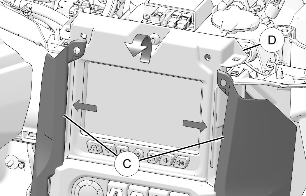
Plug Center Console LED lights (1B) into two openings in center console trim. Install straight down to align tabs.

Loosely route wiring as shown. Connector (1C) routes to passenger side of vehicle.

Route wiring lead under coolant bottle and plug Chassis Harness Connector (1C) into chassis harness.

Plug Passenger Footwell LED lights (1D) into two openings above passenger footwell. Install straight down to align tabs.

Secure LED harness to vehicle harness with cable tie 2.

Remove and keep four screws A from ECU B.

Leave wiring connected and rotate ECU away from mounting bracket.
Remove and keep three screws C from fuse block bracket D.

Slide fuse block bracket D forward until two holes for LED lights can be seen.

Route Driver Footwell LED lights (1D) to two openings above driver footwell. Install straight down to align tabs.

Slide fuse block bracket D back into place and secure with three screws C. Torque screws to specification.
Fuse Block Bracket Screw C:
65 in-lbs (7.3 N·m)
Set ECU B back into place and secure four retained screws A. Torque screws to specification.
ECU Mounting Screw A:
15 in-lbs (1.7 N·m)
Carefully bend top of trim panel C sides outward. Lift and tilt center console frame D into place.
Install two retained push-pin rivets A and two screws B into trim panels. Torque screws to specification.
Ride Command Trim Screw B:
36 in-lbs (4 N·m)
If equipped, connect dash tweeter speakers to main vehicle harness.
Set upper dash panel in place and loosely install eight retained screws A and B.

Torque eight screws to specification.
Inner Upper Dash Panel Screws A:
65 in-lbs (7.4 N·m)
Outer Upper Dash Panel Screws B:
36 in-lbs (4 N·m)
Set side trim panel C in place and loosely install two retained screws A and install two retained push pin rivets B.
Torque two screws to specification.
Side Trim Panel Screws A:
10 in-lbs (1.1 N·m)
Repeat steps 1–2 for opposite side trim panel.
Put small end of panels under dash and rotate to press clips into place.

Set windshield B in place and attach with retained fasteners A.
Torque fasteners to specification (if applicable).
Windshield Threaded Fastener:
13 in-lbs (1.4 N·m)
If equipped, install screw, washer and O-ring into center windshield mount. Torque screw to specification.
Windshield Center Mount Screw:
13 in-lbs (1.4 N·m)
Set mirror in place and attach with two mirror mounting screws.
Torque mounting screws to specification.
Mirror Mount Screws:
35 ft-lbs (47 N·m)
Repeat for opposite side mirror.
LED lighting switch has three positions
Up position: White lighting
Middle Position: OFF
Down position: Color (Blue, red, etc.) lighting

A feedback form has been created for the installer to provide any comments, questions or concerns about the installation instructions. The form is viewable on mobile devices by scanning the QR code or by clicking HERE if viewing on a PC.

Was this helpful?