|
Throttle Position Sensor 1 Voltage High
|
51
|
3
|
P0123
|
This Trouble Code sets if the Throttle Position Sensor Signal
is above 4.61 Volts. Can be caused by Damaged Wiring, a faulty Throttle
Position Sensor or ECU / Connections.
|
|
Throttle Position Sensor 1 Voltage Low
|
51
|
4
|
P0122
|
This Trouble Code sets if the Throttle Position Sensor Signal
is below 0.7 Volts. Can be caused by Damaged Wiring, a faulty Throttle
Position Sensor or ECU / Connections.
|
|
TPS Unrealistic Transition
|
51
|
10
|
P0120
|
This Trouble Code sets when the Throttle Position Sensor
Signal changes too rapidly to be correct. The condition can be caused
by intermittent connections causing the TPS voltage to jump around
between readings. Check for damaged connectors or wiring.
|
|
Vehicle Speed Sensor Signal Fault
|
84
|
2
|
P0503
|
This Trouble Code Sets if the Vehicle Speed Signal is intermittent
or missing. Can be caused by Damaged Wiring/Connections or a Faulty/Loose
Vehicle Speed Sensor.
|
|
Intake Air Temp Sensor Circuit Voltage High
|
105
|
3
|
P0113
|
This Trouble Code sets if the Intake Air Temperature Sensor
Signal is above 4.9 Volts. Can be caused by Damaged Wiring, a faulty
Intake Air Temperature Sensor or ECU / Connections.
|
|
Intake Air Temp Sensor Circuit Voltage Low
|
105
|
4
|
P0112
|
This Trouble Code sets if the Intake Air Temperature Sensor
Signal is below 0.19 Volts. Can be caused by Damaged Wiring, a faulty
Intake Air Temperature Sensor or ECU / Connections.
|
|
IAT Sensor Abnormal Rate of Change
|
105
|
10
|
P0114
|
This Trouble Code sets if the Intake Air Temperature Sensor
Signal indicates an Unrealistic Rate of Change. Can be caused by Damaged
Wiring, a faulty Intake Air Temperature Sensor or ECU / Connections.
|
|
Barometric Sensor Circuit Voltage High
|
108
|
3
|
P2229
|
This Trouble Code Sets if the Barometric Pressure Sensor
Signal Circuit is Open or Shorted to Battery Voltage. Can be caused
by Damaged Wiring/Connections, a Faulty Ambient Pressure Sensor or
ECU.
|
|
Barometric Sensor Circuit Voltage Low
|
108
|
4
|
P2228
|
This Trouble Code Sets if the Barometric Pressure Sensor
Signal Circuit is Shorted to Ground. Can be caused by Damaged Wiring/Connections,
a Faulty Ambient Pressure Sensor or ECU.
|
|
Engine Temperature Over-Temp Shutdown
|
110
|
0
|
P1217
|
This Trouble Code sets if the Engine Temperature indicates
a Critical Over Temperature Condition and the engine is running in
a limp-home mode to prevent damage. Can be caused by any failure that
would cause the engine to overheat.
|
|
Engine Temperature Sensor Circuit Voltage High
|
110
|
3
|
P0118
|
This Trouble Code sets if the Engine Coolant Temperature
Sensor Signal is above 4.8 Volts. Can be caused by Damaged Wiring,
a faulty Coolant Temperature Sensor or ECU / Connections.
|
|
Engine Temperature Sensor Circuit Voltage Low
|
110
|
4
|
P0117
|
This Trouble Code sets if the Engine Coolant Temperature
Sensor Signal is below 0.1 Volts. Can be caused by Damaged Wiring,
a faulty Coolant Temperature Sensor or ECU / Connections.
|
|
Engine Temperature Abnormal Rate of Change
|
110
|
10
|
P0119
|
This Trouble Code sets if the Engine Coolant Temperature
Sensor Signal is erratic. Can be caused by Damaged Wiring, a faulty
Coolant Temperature Sensor or ECU / Connections.
|
|
Engine Over-temperature Fault
|
110
|
16
|
P0217
|
This Trouble Code sets if the Engine Temperature indicates
a Severe Over Temperature Condition. Can be caused by any failure
that would cause the engine to overheat. This Trouble Code Does Not
indicate a problem with the Engine Temperature Sensor.
|
|
Fuel Rail Pressure Sensor Voltage High
|
157
|
3
|
P0193
|
This trouble code sets if the Fuel Pressure Sensor Voltage
is above 4.85V. Can be caused by Damaged Wiring, a faulty Fuel Pressure
Sensor or ECU / Connections.
|
|
Fuel Rail Pressure Sensor Voltage Low
|
157
|
4
|
P0192
|
This Trouble Code Sets if the Fuel Pressure Sensor Circuit
is below 0.1V. Can be caused by Damaged Wiring, a faulty Fuel Pressure
Sensor or ECU / Connections.
|
|
Fuel Rail Pressure Below Power Limit
|
157
|
18
|
P0196
|
This Trouble Code Sets if the Fuel Pressure drops below
3Bar (43.5PSI) for 10 seconds. Can be caused by a faulty Pump Flange
Assembly (PFA).
|
|
Battery Voltage High
|
158
|
3
|
P1567
|
This Trouble Code Sets if the if the Battery Voltage is
above 15.0V. Can be caused by Damaged Wiring, a faulty Battery or
ECU / Connections.
|
|
Battery Voltage Low
|
158
|
4
|
P1566
|
This Trouble Code Sets if the if the Battery Voltage is
below 10.0V. Can be caused by Damaged Wiring, a faulty Battery or
ECU / Connections.
|
|
Exhaust Over-Temperature Shutdown
|
173
|
0
|
P1517
|
This Trouble Code Sets if the engine was shut down due to
High Exhaust Temperature. Can be caused by a Faulty Exhaust Temperature
Sensor/Connections or Lean Air/Fuel Ratio causing high exhaust temperature.
|
|
Exhaust Temp Sensor Signal High
|
173
|
3
|
P0546
|
This Trouble Code sets if the engine has been running above
3000 RPM for more than 2 minutes and the Exhaust Temperature Sensor
Signal is above 4.90 Volts. Can be caused by Damaged Wiring, a faulty
Engine Temperature Sensor or ECU / Connections.
|
|
Exhaust Temp Sensor Signal Low
|
173
|
4
|
P0545
|
This Trouble Code sets if the engine has been running above
3000 RPM for more than 2 minutes and the Exhaust Temperature Sensor
Signal is below 0.06 Volts. Can be caused by Damaged Wiring, a faulty
Engine Temperature Sensor or ECU / Connections.
|
|
Exhaust Temp Sensor Unrealistic Transition
|
173
|
10
|
P1546
|
This Trouble Code sets if the Exhaust Temperature Sensor
Signal changes too quickly to be considered a Realistic Value. Can
be caused by Damaged Wiring, a faulty Exhaust Temperature Sensor or
ECU / Connections.
|
|
Fuel Temperature Sensor Voltage High
|
174
|
3
|
P1322
|
This trouble code sets if the Fuel Temperature Sensor Voltage
is above 4.81V. Can be caused by Damaged Wiring, a faulty Fuel Pressure
Sensor or ECU / Connections.
|
|
Fuel Temperature Sensor Voltage Low
|
174
|
4
|
P1323
|
This trouble code sets if the Fuel Temperature Sensor Voltage
is Below 0.01V. Can be caused by Damaged Wiring, a faulty Fuel Pressure
Sensor or ECU / Connections.
|
|
ECU Memory Checksum Error
|
628
|
13
|
P0601
|
This Trouble Code Sets if an Internal Memory Fault is detected
in the Engine Controller. Can only be caused by a defective ECU.
|
|
Crankshaft Sensor Signal Fault
|
636
|
2
|
P0335
|
This Trouble Code sets if the Engine is Running and No Signal
is Detected from the 5X Crankshaft Sensor. Can be caused by Damaged
Wiring, a faulty Crankshaft Sensor or ECU / Connections.
|
|
Crankshaft Position Sensor Circuit Fault
|
636
|
8
|
P0336
|
This Trouble Code sets if the Engine is Running and the
number of pulses from the 5X Crankshaft Sensor is not correct. Can
be caused by Damaged Wiring, a faulty Crankshaft Sensor or ECU / Connections.
|
|
MAG Cylinder Port Injector Short to B+
|
651
|
3
|
P0262
|
This Trouble Code sets if a Short to Voltage is detected
in the MAG Cylinder Port Injector Control Circuit. Can be caused by
Damaged Wiring, a faulty Fuel Injector or ECU / Connections.
|
|
MAG Cylinder Port Injector Open Circuit
|
651
|
5
|
P0261
|
This Trouble Code sets if an Open Circuit Condition is detected
in the MAG Cylinder Port Injector Control Circuit. Can be caused by
Damaged Wiring, a faulty Fuel Injector or ECU / Connections.
|
|
PTO Cylinder Port Injector Short to B+
|
652
|
3
|
P0265
|
This Trouble Code sets if a short to Voltage is detected
in the PTO Cylinder Port Injector Control Circuit. Can be caused by
Damaged Wiring, a faulty Fuel Injector or ECU / Connections.
|
|
PTO Cylinder Port Injector Open Circuit
|
652
|
5
|
P0264
|
This Trouble Code sets if an Open Circuit Condition is detected
in the PTO Cylinder Port Injector Control Circuit. Can be caused by
Damaged Wiring, a faulty Fuel Injector or ECU / Connections.
|
|
Ignition Coil 1 (MAG) Driver Circuit Open
|
1268
|
5
|
P1351
|
This Trouble Code Sets if Ignition Coil 1 (MAG) Driver Circuit
is Open. Can be caused by Damaged Wiring/Connections, a Faulty MAG
Ignition Coil or ECU.
|
|
Ignition Coil 2 (PTO) Driver Circuit Open
|
1269
|
5
|
P1352
|
This Trouble Code Sets if Ignition Coil 2 (PTO) Driver Circuit
is Open. Can be caused by Damaged Wiring/Connections, a Faulty PTO
Ignition Coil or ECU.
|
|
Max. Detonation Correction Limit Reached, MAG Cylinder
|
1352
|
0
|
P1336
|
This Trouble Code Sets if the Engine Controller Reaches
the Maximum Detonation Control Limit by Fuel Correction on the Mag
Cylinder Can be caused by Incorrect Fuel (low octane or Ethanol content)
or Low Fuel Pressure.
|
|
Cylinder 1 (MAG) Knock Level Critical
|
1352
|
16
|
P2336
|
This Trouble Code Sets if Cylinder 1 (MAG) Knock Sensor
reaches a Critical Level. Can be caused by Excessive Knock (Fuel Problems),
a Lean Running Condition or Engine Mechanical Problems.
|
|
Max. Detonation Correction Limit Reached, PTO Cylinder
|
1353
|
0
|
P1337
|
This Trouble Code Sets if the Engine Controller Reaches
the Maximum Detonation Control Limit by Fuel Correction on the PTO
Cylinder. Can be caused by Incorrect Fuel (low octane or Ethanol content)
or Low Fuel Pressure.
|
|
Cylinder 2 (PTO) Knock Level Critical
|
1353
|
16
|
P2337
|
This Trouble Code Sets if Cylinder 2 (PTO) Knock Sensor
reaches a Critical Level. Can be caused by Excessive Knock (Fuel Problems),
a Lean Running Condition or Engine Mechanical Problems.
|
|
Sensor Supply Voltage 1 Low
|
3509
|
4
|
P06B1
|
This Trouble Code sets if the Sensor Supply 1 Voltage is
below an acceptable limit (approx. 4.50 Volts). Can be caused by Damaged
Wiring or Faulty/Shorted Sensors.
|
|
Sensor Supply Voltage 2 Low
|
3510
|
4
|
P06B4
|
This Trouble Code sets if the Sensor Supply 2 Voltage is
below an acceptable limit (approx. 4.50 Volts). Can be caused by Damaged
Wiring or Faulty/Shorted Sensors.
|
|
Vehicle Speed Sensor Supply Voltage Low
|
3511
|
4
|
P16B6
|
This Trouble Code sets if the Sensor Supply 3 Voltage is
below an acceptable limit (approx. 4.5 Volts). Can be caused by Damaged
Wiring or Faulty Sensor/shorted to ground.
|
|
Oil Pump Driver Circuit Open
|
3589
|
5
|
P16BA
|
This Trouble Code Sets if the Oil Pump Driver Circuit is
Open. Can be caused by Damaged Wiring/Connections, a Faulty Oil Pump/Connections
or Faulty ECU/Connections.
|
|
Oil Pump Driver Circuit Fault
|
3589
|
12
|
P16BC
|
This Trouble Code Sets if a Failure is Detected in the Oil
Pump Driver Circuit. Can be caused by Damaged Wiring/Connections,
a Faulty Oil Pump/Connections or Faulty ECU/Connections.
|
|
Injector Output Supply 2 Voltage High
|
3598
|
3
|
P16A9
|
This Trouble Code sets if the Injector Output Supply 2 Voltage
is above an acceptable limit. Can be caused by Damaged Wiring or Faulty/Shorted
Connectors.
|
|
Injector Output Supply 2 Voltage Low
|
3598
|
4
|
P16A8
|
This Trouble Code sets if the Injector Output Supply 2 Voltage
is below an acceptable limit. Can be caused by Damaged Wiring or Faulty/Shorted
Connectors.
|
|
Regulator: Critical Voltage Too Low
|
32523
|
4
|
P1609
|
This Trouble Code Sets if the Regulator has detected Low
Voltage in the Critical Circuit. Can be caused by damaged Regulator
wiring or connections, electrical modifications or faulty Regulator.
|
|
Regulator: Critical Open Circuit
|
32523
|
5
|
P160B
|
This Trouble Code Sets if the Regulator has detected an
Open Circuit in the Critical Circuit. Can be caused by damaged wiring,
faulty headlight, Fuel Pump or Regulator connections.
|
|
Regulator: Critical Short Circuit
|
32523
|
6
|
P160C
|
This Trouble Code Sets if the Regulator has detected Excessive
Current in the Critical Circuit. Can be caused by damaged wiring,
faulty headlight, Fuel Pump or Regulator connections.
|
|
Regulator: Critical Voltage Too High
|
32523
|
15
|
P160D
|
This Trouble Code Sets if the Regulator has detected Excessive
Voltage in the Critical Circuit. Can be caused by damaged wiring,
faulty headlight, Fuel Pump or Regulator connections.
|
|
Regulator: Chassis Voltage Too Low
|
32523
|
20
|
P160E
|
This Trouble Code Sets if the Regulator has detected Low
Voltage in the Chassis Circuit. Can be caused by damaged wiring or
faulty grip heaters.
|
|
Regulator: Chassis Short Circuit
|
32523
|
22
|
P160F
|
This Trouble Code Sets if the Regulator has detected Excessive
Current Draw in the Chassis Circuit. Can be caused by damaged wiring
or faulty grip heaters.
|
|
Regulator: Chassis Voltage Too High
|
32523
|
31
|
P1610
|
This Trouble Code Sets if the Regulator has detected Excessive
Voltage in the Chassis Circuit. Can be caused by damaged wiring, Regulator
connections or Regulator.
|
|
Regulator: Stator Output Low
|
32531
|
36
|
P1510
|
This Trouble Code Sets if the Regulator has detected a Low
Voltage condition in the Stator. Can be caused by a Short to ground
in the Stator or damaged Stator wiring.
|
|
Regulator: Stator Open Circuit
|
32531
|
37
|
P1511
|
This Trouble Code Sets if the Regulator has detected an
Open Circuit condition in the Stator. Can be caused by an Open Circuit
in the Stator or damaged Stator wiring.
|
|
Exhaust Temperature Sensor 2 - Temperature Too High
|
520173
|
0
|
P1487
|
This Trouble Code sets if the Exhaust Temperature 2 Signal
is greater than 750C. Can be caused by a Faulty Exhaust Temperature
Sensor/Connections or Lean Air/Fuel Ratio causing high exhaust temperature.
|
|
Exhaust Temperature Sensor 2 Voltage High
|
520173
|
3
|
P1484
|
This Trouble Code Sets if the if the Exhaust Temp Sensor
2 Voltage is above 4.96V. Can be caused by Damaged Wiring, a faulty
Exhaust Temp Sensor or ECU / Connections.
|
|
Exhaust Temperature Sensor 2 Voltage Low
|
520173
|
4
|
P1485
|
This Trouble Code Sets if the if the Exhaust Temp Sensor
2 Voltage is Below 0.06V. Can be caused by Damaged Wiring, a faulty
Exhaust Temp Sensor or ECU / Connections.
|
|
Exhaust Temperature Sensor 2 Abnormal Rate of Change
|
520173
|
10
|
P1486
|
This Trouble Code sets if the Exhaust Temperature Sensor
Signal changes too quickly to be considered a Realistic Value. Can
be caused by Damaged Wiring, a faulty Exhaust Temperature Sensor or
ECU / Connections.
|
|
Exhaust Temperature Sensor 2 Mismatch with Sensor 1
|
520173
|
14
|
P1488
|
This Trouble Code Sets when Exhaust Temperature Sensor 2
signal is 250C greater than Exhaust Temp Sensor 1 signal. The condition
can be caused by Damaged Wiring, faulty Exhaust Temperature Sensor
or ECU / Connections.
|
|
ECU Supply Voltage High
|
520174
|
3
|
P1341
|
This Trouble Code sets if the ECU Supply Voltage is above
17.00V. Can be based by faulty wiring, faulty regulator or ECU / Connections
|
|
ECU Supply Voltage Low
|
520174
|
4
|
P1342
|
This Trouble Code sets if the ECU Supply Voltage is below
10.00V. Can be based by faulty wiring, faulty regulator or ECU / Connections.
|
|
Critical Supply Voltage High
|
520175
|
3
|
P1343
|
This Trouble Code sets if the Critical Supply Voltage is
above 17.00V. Can be based by faulty wiring, faulty regulator or ECU
/ Connections.
|
|
Critical Supply Voltage Low
|
520175
|
4
|
P1344
|
This Trouble Code sets if the Critical Supply Voltage is
below 10.00V. Can be cbased by faulty wiring, faulty regulator or
ECU / Connections.
|
|
Chassis Supply Voltage High
|
520176
|
3
|
P1345
|
This Trouble Code sets if the Chassis Supply Voltage is
above 18.00V. Can be based by faulty wiring, faulty regulator or ECU
/ Connections.
|
|
Chassis Supply Voltage Low
|
520176
|
4
|
P1346
|
This Trouble Code sets if the Chasssis Supply Voltage is
below 14.00V. Can be based by faulty wiring, faulty regulator or ECU
/ Connections.
|
|
Peak Injector Voltage High
|
520177
|
3
|
P1347
|
This Trouble Code sets if the Peak Injector Supply Voltage
is above 24.00V. Can be based by faulty wiring, faulty regulator or
ECU / Connections.
|
|
Peak Injector Voltage Low
|
520177
|
4
|
P1348
|
This Trouble Code sets if the Peak Injector Supply Voltage
is below 20.00V. Can be based by faulty wiring, faulty regulator or
ECU / Connections.
|
|
EV Actuator Position High in Open Position
|
520178
|
16
|
P2627
|
This Trouble Code sets if the Exhaust Valve Actuator Position
is greater than 80.0% when trying to achieve Open position. This can
be caused by a faulty Exhaust Valve Actuator, Broken Cable or Broken
Exhaust Valve Assembly.
|
|
EV Actuator Position Low in Open Position
|
520178
|
18
|
P2628
|
This Trouble Code sets if the Exhaust Valve Actuator Position
is less than 70.0% when trying to achieve Open position. This can
be caused by a faulty Exhaust Valve Actuator, Broken Cable or Broken
Exhaust Valve Assembly.
|
|
EV Actuator Position High in Mid Position
|
520179
|
16
|
P2629
|
This Trouble Code sets if the Exhaust Valve Actuator Position
is greater than 55.0% when trying to achieve Mid position. This can
be caused by a faulty Exhaust Valve Actuator, Broken Cable or Broken
Exhaust Valve Assembly.
|
|
EV Actuator Position Low in Mid Position
|
520179
|
18
|
P2630
|
This Trouble Code sets if the Exhaust Valve Actuator Position
is less than 45.0% when trying to achieve Mid position. This can be
caused by a faulty Exhaust Valve Actuator, Broken Cable or Broken
Exhaust Valve Assembly.
|
|
EV Actuator Position High in Closed Position
|
520180
|
16
|
P2631
|
This Trouble Code sets if the Exhaust Valve Actuator Position
is greater than 30.0% when trying to achieve Closed position. This
can be caused by a faulty Exhaust Valve Actuator, Broken Cable or
Broken Exhaust Valve Assembly.
|
|
EV Actuator Position Low in Closed Position
|
520180
|
18
|
P2632
|
This Trouble Code sets if the Exhaust Valve Actuator Position
is less than 20.2% when trying to achieve Closed position. This can
be caused by a faulty Exhaust Valve Actuator, Broken Cable or Broken
Exhaust Valve Assembly.
|
|
Throttle Release Switch Signal Circuit Short to Voltage
|
520194
|
3
|
P1555
|
This Trouble Code Sets if the Throttle Release Switch Signal
is Open Circuit or Shorted to Battery Voltage. Can be caused by Damaged
Wiring/Connections, a Faulty Throttle Safety Switch or ECU.
|
|
Throttle Release Switch Signal Circuit Short to Ground
|
520194
|
4
|
P1554
|
This Trouble Code Sets if the Throttle Safety Switch Signal
is Shorted to Ground. Can be caused by Damaged Wiring/Connections,
a Faulty Throttle Safety Switch or ECU.
|
|
Throttle Stuck Error
|
520194
|
7
|
P1552
|
This Trouble Code Sets if the Throttle Release Switch Signal
Indicates a Throttle Stuck Open. Can be caused by a Stuck Throttle
or Misadjusted/Stuck Throttle Linkage.
|
|
Accessory Relay Driver Circuit Short to B+
|
520219
|
3
|
P1647
|
This Trouble Code Sets if the Accessory Relay Driver Circuit
is Shorted to Voltage. Can be caused by Damaged Wiring/Connections,
a Faulty Accessory Relay or ECU.
|
|
Accessory Relay Driver Circuit Open
|
520219
|
5
|
P1646
|
This Trouble Code Sets if the Accessory Relay Driver Circuit
is Open. Can be caused by Damaged Wiring/Connections, a Accessory
Ignition Relay or ECU.
|
|
Charge Relay Driver Circuit Short to B+
|
520220
|
3
|
P163D
|
This Trouble Code Sets if the Charge Relay Driver Circuit
is Shorted to Voltage. Can be caused by Damaged Wiring/Connections,
a Faulty Charge Relay or ECU.
|
|
Charge Relay Driver Circuit Open
|
520220
|
5
|
P163C
|
This Trouble Code Sets if the Charge Relay Driver Circuit
is Open. Can be caused by Damaged Wiring/Connections, a Charge Relay
or ECU.
|
|
Oil Pump or Fuel Injector Offset not Programmed
|
520241
|
13
|
P1278
|
This Trouble Code Sets if Either the Fuel Injector or Oil
Injection Pump Calibration has Not Been Programmed. Update the Injector/Oil
Pump Settings. WARNING: Do Not Operate the Vehicle with This Trouble
Code Set!
|
|
Ground Speed Pulses Per Mile not Programmed
|
520242
|
13
|
P1279
|
This Trouble Code Sets if the Vehicle Speed Sensor Setting
is Not Properly Programmed in the ECU. Reset the ECU Offset Values
to Resolve this Fault Condition.
|
|
Exhaust Valve Position Out of Range (Open)
|
520325
|
31
|
P140A
|
This Trouble Code sets if: Valve UP position voltage out
of range. Check the following: (1) Measure cable travel length, (2)
Verify smooth valve operation by operating the cable by hand through
its full travel, (3) Relearn EVIf no problem.
|
|
Exhaust Valve Position Out of Range (Mid)
|
520326
|
31
|
P140B
|
This Trouble Code sets if: Valve MID position voltage out
of range. Check the following: (1) Measure cable travel length, (2)
Verify smooth valve operation by operating the cable by hand through
its full travel, (3) Relearn EVIf no problem.
|
|
Exhaust Valve Position Out of Range (Closed)
|
520327
|
31
|
P140C
|
This Trouble Code sets if: Valve DOWN position voltage out
of range. Check the following: If occasional, this fault is nothing
to be concerned about If persistent: Measure cable travel length and
Verify smooth valve operation.
|
|
Riding With Brakes On Moderately Severe
|
520555
|
31
|
C2418
|
This Trouble Code Sets if the Sled has been driven with
the brakes applied continuously for 10 seconds, 4500 RPM.
|
|
Riding With Brakes On Most Severe
|
520556
|
31
|
C2419
|
This Trouble Code Sets if the Sled has been driven with
the brakes applied continuously for 20 seconds , 4500 RPM.
|
|
Regulator Near Thermal Shutdown
|
520660
|
31
|
P161B
|
This Trouble Code Sets if the Regulator is near the thermal
shutdown point. Can be caused by excessive power consumption or insufficient
cooling air flow.
|
|
Batch Fire Detection
|
523959
|
31
|
P3022
|
This Trouble Code Sets if the engine is in "Batch Fire Mode".
Can be caused by Damaged Wiring, a faulty Crankshaft Sensor or ECU
/ Connections.
|
|
Exhaust Valve Actuator Short Circuit
|
523958
|
3
|
P3023
|
This trouble code sets if the ECU detects a short in the
EV Actuator Drive circuit. Can be caused by Damaged Wiring, Faulty
EV Actuator, or ECU / Connections. Inspect EV Actuator Drive wires.
(White/Green & White/Blue).
|
|
Exhaust Valve Actuator Open Circuit
|
523958
|
5
|
P3024
|
This trouble code sets if the ECU detects low current or
an open EV Actuator Drive circuit. Can be caused by Damaged Wiring,
Faulty EV Actuator, or ECU / Connections. Inspect EV Actuator Drive
wires. (White/Green & White/Blue).
|
|
Exhaust Valve Actuator Open Circuit
|
523958
|
4
|
P3025
|
This trouble code sets if the ECU detects low current or
an open EV Actuator Drive circuit. Can be caused by Damaged Wiring,
Faulty EV Actuator, or ECU / Connections. Inspect EV Actuator Drive
wires. (White/Green & White/Blue).
|
|
Exhaust Valve Actuator Over Current
|
523958
|
6
|
P3026
|
This trouble code sets if the ECU detects high current on
the EV Actuator Drive circuit. Can be caused by Damaged Wiring, Faulty
EV Actuator, or ECU / Connections. Inspect EV Actuator Drive wires.
(White/Green & White/Blue).
|
|
Exhaust Valve Actuator Internal IC Voltage High
|
523957
|
3
|
P3027
|
This trouble code sets if the ECU has detected a Exhaust
Valve Actuator internal IC voltage above 6V. Can be caused by a faulty
ECU.
|
|
Exhaust Valve Actuator Internal IC Voltage Low
|
523957
|
4
|
P3028
|
This trouble code sets if the ECU has detected a Exhaust
Valve Actuator internal IC voltage Below 4V. Can be caused by a faulty
ECU.
|
|
Exhaust Valve Actuator Internal IC Over Current / Over Temp
|
523957
|
6
|
P3029
|
This trouble code sets if the ECU has detected a Exhaust
Valve Actuator internal IC current above 2A or 200C. Can be caused
by a faulty ECU.
|
|
Exhaust Valve Actuator Internal IC Communication Loss
|
523957
|
19
|
P3032
|
This trouble code sets if the ECU loses communication with
the Exhaust Valve Actuator IC. Can be cause by a faulty ECU.
|
|
Exhaust Valve Actuator Position Sensor Voltage High
|
523956
|
3
|
P3033
|
This trouble code sets if the Exhaust Valve Actuator Position
Sensor voltage is greater than 4.5V for 1 sec. Can be caused by Damaged
wiring, Faulty EV actuator, or ECU / Connections. Inspect EV Actuator
Position Sensor wires. Power: Red/White. Ground: Brown/White. Feedback:
Dark Green/Orange.
|
|
Exhaust Valve Actuator Position Sensor Voltage Low
|
523956
|
4
|
P3034
|
This trouble code sets if the Exhaust Valve Actuator Position
Sensor voltage is Less than 0.4V for 1 sec. Can be caused by Damaged
wiring, Faulty EV actuator, or ECU / Connections. Inspect EV Actuator
Position Sensor wires. Power: Red/White. Ground: Brown/White. Feedback:
Dark Green/Orange.
|
|
Exhaust Valve Actuator Abnomral Rate of Change
|
523956
|
10
|
P3035
|
This trouble code sets if the Exhaust Valve Actuator Position
Sensor voltage is Less than 0.4V for 1 sec. Can be caused by Damaged
wiring, Faulty EV actuator, or ECU / Connections. Inspect EV Actuator
Position Sensor wires. Power: Red/White. Ground: Brown/White. Feedback:
Dark Green/Orange.
|
|
Exhaust Valve Learning Default Position
|
520337
|
7
|
P3036
|
This trouble code sets if the Exhaust Valve Learn values
are different from the Exhaust Valve Check Values. Can be caused by
an obstruction in the Exhaust Valves, Broken Cable, or broken Exhaust
Valve.
|
|
Water Temperature Unrealistic Transition
|
110
|
10
|
P0119
|
This trouble code sets if the water temperature changes
by 20C in 1 sec 3 times. Can be caused by Faulty Wiring, Faulty Water
Temperature Sensor, or Faulty ECU.
|


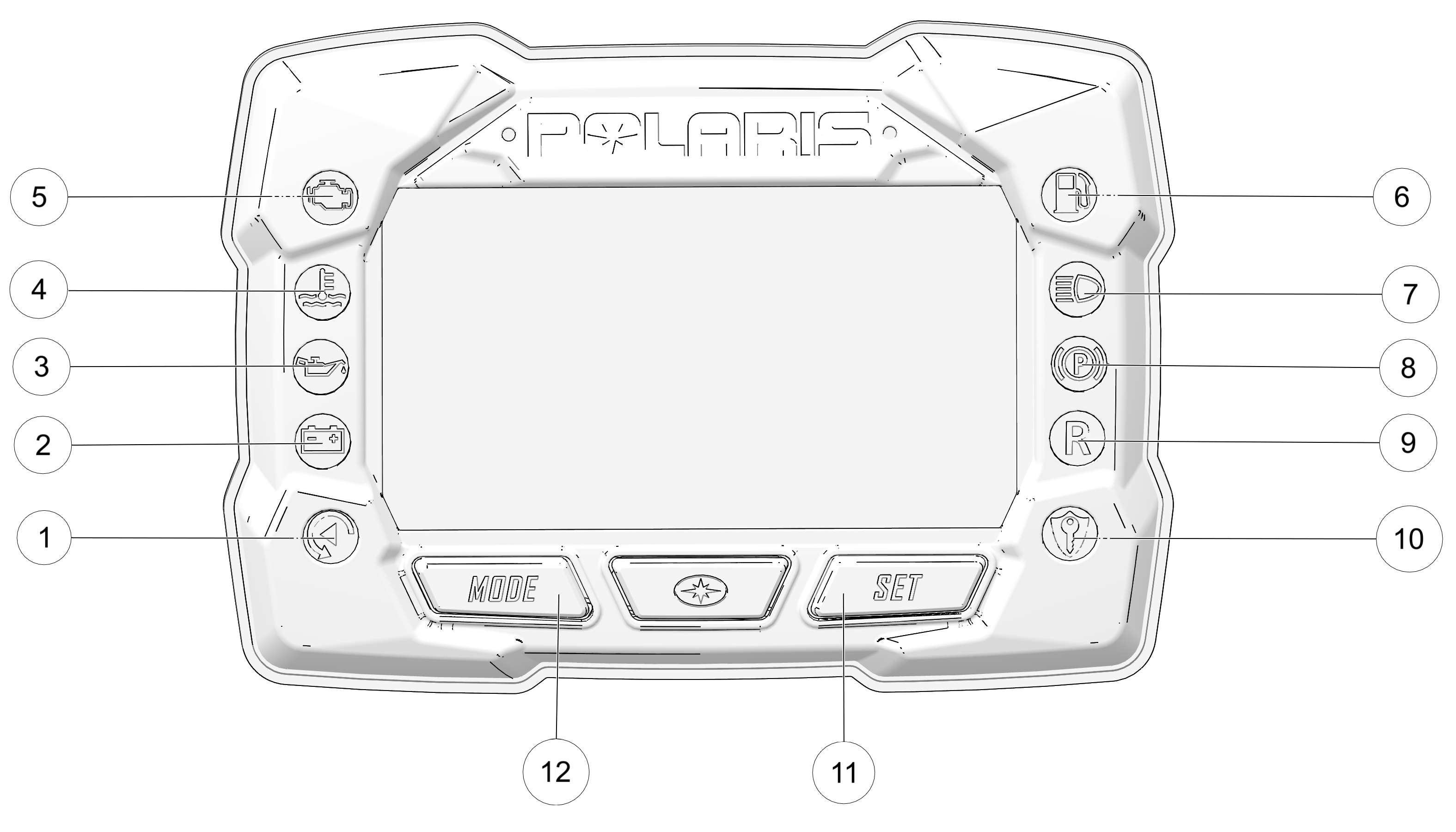


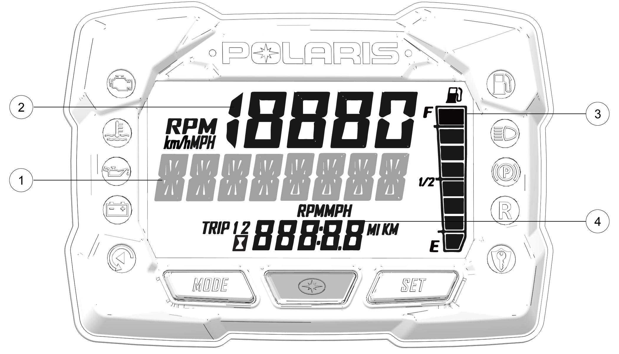
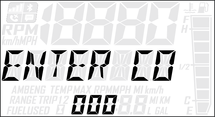
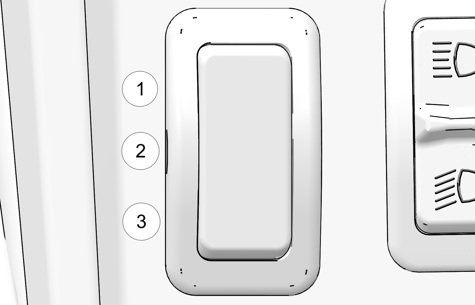
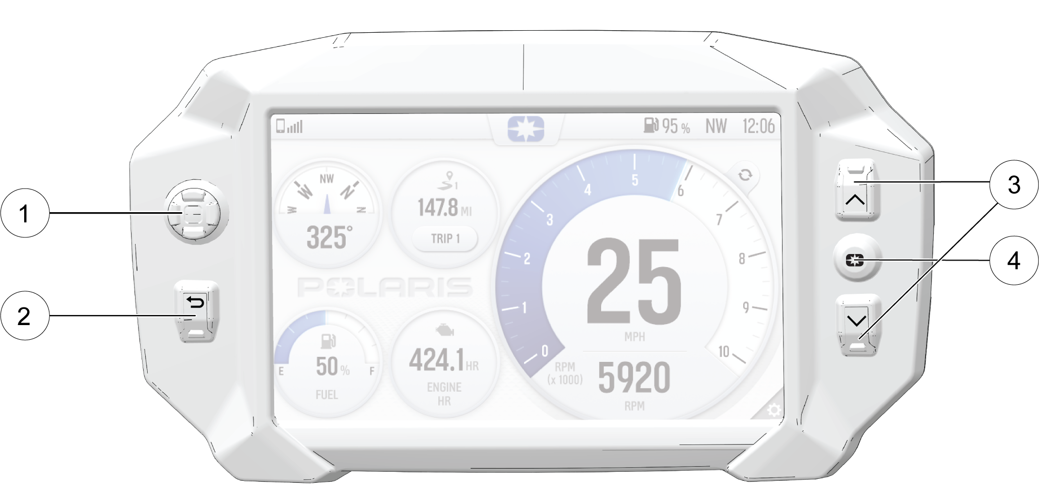
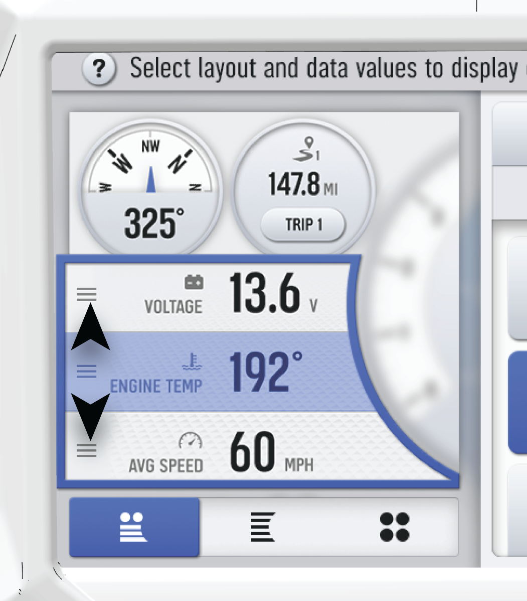
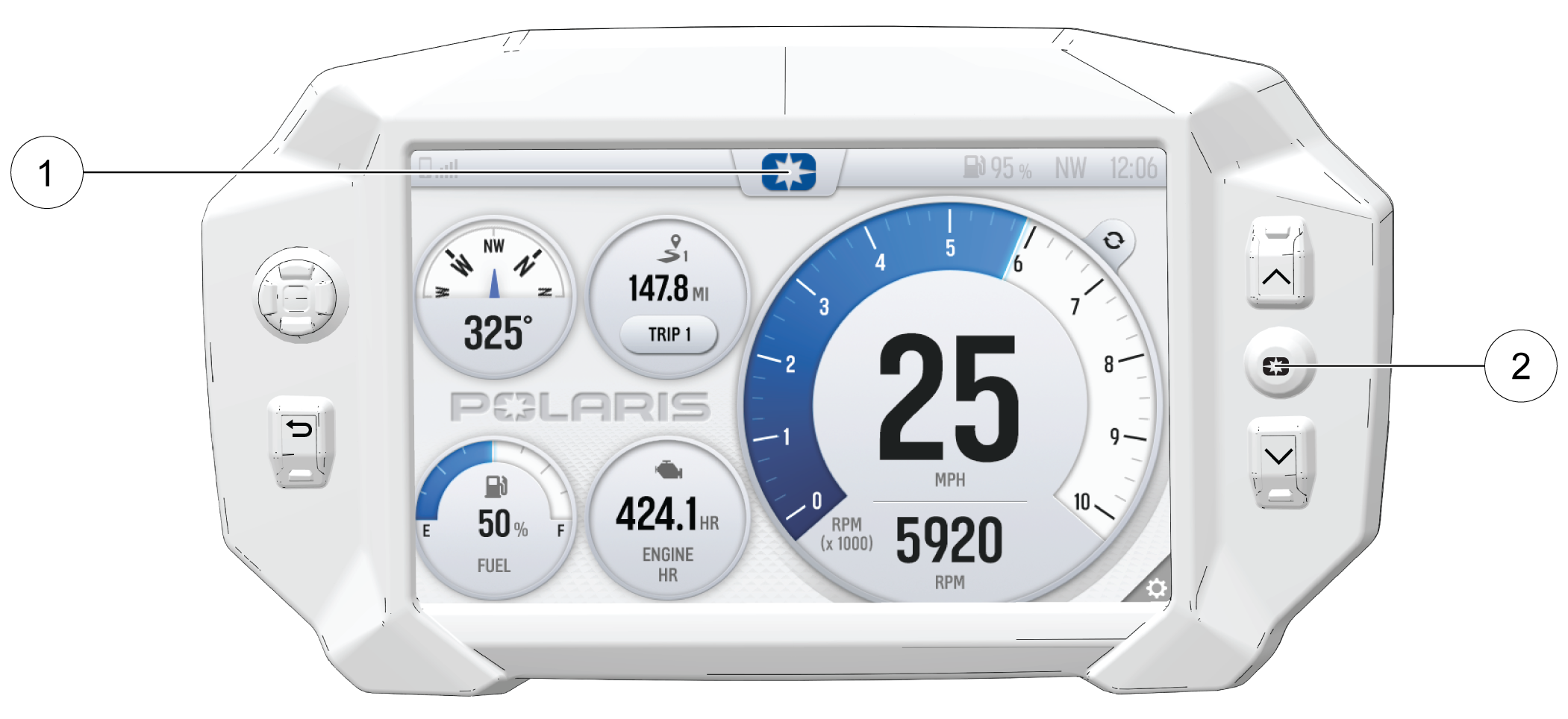
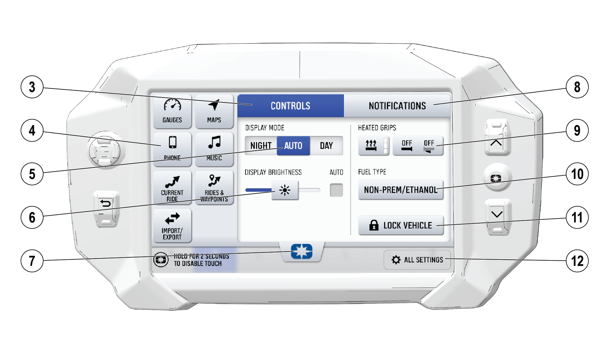
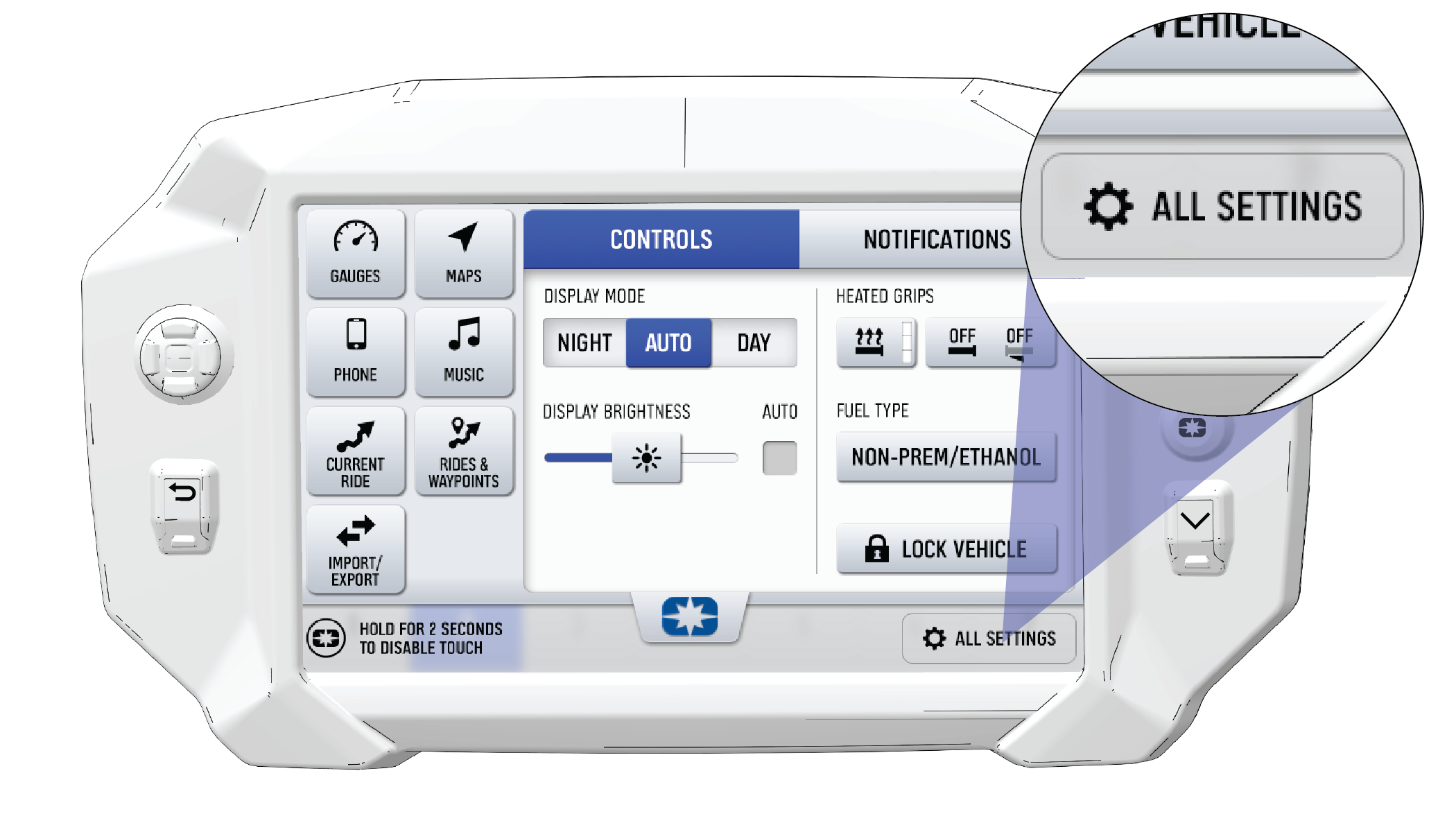
 button on the instrument cluster to enter the Options Menu.