i 2023 RANGER KINETIC Owner’s Manual

|
| 2023 Owner’s Manual |
| RANGER XP KINETIC Premium RANGER XP KINETIC Ultimate |
The Owner's Manual for this vehicle contains warnings, instructions and other information you must read and fully understand before safely riding or performing maintenance on this vehicle. Always follow the warnings and instructions in Owner's Manual.
Click the link above for the Table Of Contents, or download a full PDF of the Owner Manual in the Owner Support area of Polaris.com.
|
|
| 2023 Owner’s Manual |
| RANGER XP KINETIC Premium RANGER XP KINETIC Ultimate |
Unless noted, trademarks are the property of Polaris Industries Inc.
Recreational Off-Highway Vehicle Association® and ROHVA® are registered trademarks of Recreational Off-Highway Vehicle Association. BatteryMINDer® is a registered trademark of VDC Electronics Inc. Loctite® is a registered trademark of Henkel Corporation. NYOGEL® is a registered trademark of Nye Lubricants, Inc. WD-40® is registered to WD-40 Manufacturing Company. QR Code® is a registered trademark of DENSO WAVE INCORPORATED. Apple® and APP STORE® are registered trademarks of Apple Inc. ANSI® is a registered trademark of American National Standards Institute, Inc. Bluetooth® is a registered trademark of Bluetooth Sig, Inc. Google Play® is a registered trademark of Google, Inc. Sandisk® is a registered trademark of SANDISK LLC. exFAT® is a registered trademark of Microsoft Corporation. OSHA® is a registered trademark of the Occupational Safety and Health Administration, U.S. Dept. of Labor. Tread Lightly® is a registered trademark of the United States Department of Agriculture.
Copyright 2023 Polaris Industries Inc. All information contained within this publication is based on the latest product information at the time of publication. Due to constant improvements in the design and quality of production components, some minor discrepancies may result between the actual vehicle and the information presented in this publication. Depictions and/or procedures in this publication are intended for reference use only. No liability can be accepted for omissions or inaccuracies. Any reprinting or reuse of the depictions and/or procedures contained within, whether whole or in part, is expressly prohibited.
The original instructions for this vehicle are in English. Other languages are provided as translations of the original instructions.
Printed in U.S.A.

Thank you for purchasing a POLARIS vehicle, and welcome to our world-wide family of POLARIS enthusiasts. Be sure to visit us online at www.polaris.com for the latest news, new product introductions, upcoming events, career opportunities and more.
Here at POLARIS we proudly produce an exciting line of utility and recreational products. We believe POLARIS sets a standard of excellence for all utility and recreational vehicles manufactured in the world today. Many years of experience have gone into the engineering, design, and development of your POLARIS vehicle.
For safe and enjoyable operation of your vehicle, be sure to follow the instructions and recommendations in this owner’s manual. Your manual contains instructions for minor maintenance, but information about major repairs is outlined in the POLARIS Service Manual and can be performed by a factory certified Master Service Dealer (MSD) technician.
Your POLARIS dealer knows your vehicle best and is interested in your total satisfaction. Your POLARIS dealership can perform all of your service needs during and after the warranty period.
For the most up-to-date owner’s manual visit
https://www.polaris.com/en-us/owners-manuals
.
The following signal words and symbols appear throughout this manual and on your vehicle. Your safety is involved when these words and symbols are used. Become familiar with their meanings before reading the manual.
DANGER indicates a hazardous situation which, if not avoided, WILL result in death or serious injury.
WARNING indicates a hazardous situation which, if not avoided, COULD result in death or serious injury.
CAUTION indicates a hazardous situation which, if not avoided, COULD result in minor to moderate injury.
NOTICE provides key information by clarifying instructions.
IMPORTANT provides key reminders during disassembly, assembly, and inspection of components.
The Prohibition Safety Sign indicates an action NOT to take in order to avoid a hazard.

The Mandatory Action Sign indicates an action that NEEDS to be taken to avoid a hazard.

To safely operate this vehicle, it is important to become familiar with its features, controls, and characteristics. Review all items in the Safety chapter for this vehicle that apply to you:
Operators
Riders
Owners
Trailering the Vehicle
Maintaining the Vehicle
Additionally, read the product safety labels on the vehicle and follow all rules and regulations concerning the operation of this vehicle in your area.
Polaris recommends anyone who will be operating this vehicle to take a training course. ROHVA® (Recreational Off-Highway Vehicle Association®) provides both an online safety e-course and a hands-on safety course. To access this training, visit www.rohva.org.
Other sources of safety information include the Polaris Safety Video. The Polaris Help Center also has additional information: https://ranger.polaris.com/en-us/self-help
This Off-Road Vehicle was subjected to the following tests of the National Standard for Recreational Off-Highway Vehicles, ANSI®/ROHVA® 1-2016:
Maximum Speed Capability
Service Brake Performance
Parking Brake/Mechanism Performance
Lateral Stability
Pitch Stability
Vehicle Handling
Roll Over Protective Structure (ROPS)
Occupant Retention System (ORS)
Sound Level Limits
Record your vehicle's identification numbers and key number in the spaces provided. Remove the spare key and store it in a safe place. An ignition key can be duplicated only by ordering a Polaris key blank (using your key number) and mating it with one of your existing keys. The ignition switch must be replaced if all keys are lost.
The VIN can be found stamped on a portion of the left rear frame 1, above the wheel well liner. If equipped, the VIN can be found using the NFC emblem at the front of the vehicle. See Near-field Communication (NFC)(if equipped) for details.
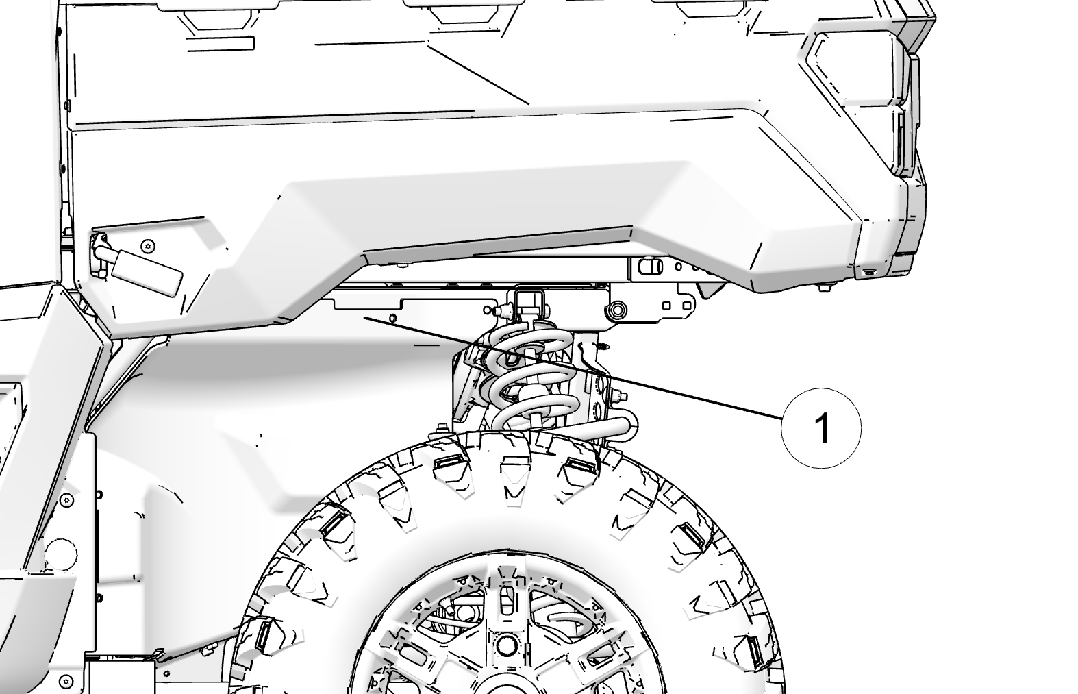
| Vehicle Model Number: | |
| Vehicle Identification Number (VIN): | |
| Key Number: | |
| NRMM Reference Number (if applicable): |
Improper use, maintenance, or modification of this vehicle can lead to serious injury or death.
Require proper use of your vehicle. Do not allow anyone to operate your vehicle or ride as a passenger unless they are properly instructed and you are sure they are willing to ride responsibly. To prevent unauthorized use, always remove the vehicle key when the vehicle is not in use.

Any modifications or installation of non-Polaris-approved accessories could increase the risk of injury. While you may find aftermarket products similar in design and quality to Polaris accessories, recognize that some aftermarket accessories or modifications are not suitable because of potential safety hazards to you or others. It is never appropriate to install any additional seating.
Check with the manufacturer to determine any potential effect of a modification or accessory on the safe use of your vehicle. You are responsible for injuries related to modifications to the vehicle. Modifications or accessories may:
Damage machine components - especially modifications that increase speed or power.
Make the vehicle less stable at higher speeds.
Add weight, reducing the amount of cargo and total weight you can carry, and raise the vehicle’s center of gravity.
Overload the vehicle’s electrical system capacity (see RANGER XP KINETIC). Blowing a fuse may cause a loss of lights or motor power.
Reduce the effectiveness of occupant protection systems, including the seatbelts and the Rollover Protective Structure (ROPS).
Void your warranty.
The vehicle ROPS, when used with the seat belts and doors/nets, provides a structure to help protect occupants. The structure will not protect occupants in all rollovers or accidents.
Make sure operators are 16 or older with a valid driver’s license. Just because a teenager has a license does not mean that they will make good judgments about driving and avoid risk taking.


POLARIS recommends that you supervise younger drivers. Set rules and put limits on how, when, and where they are allowed to use this vehicle. For example, young drivers may need to have an adult in the vehicle with them and not be allowed to drive with their friends in the vehicle.
Make sure all riders fit the vehicle. Be sure that the driver and all passengers are able to:
sit with their backs against their seat,
adjust the seat belt to fit properly,
have both feet flat on the floor, and
have both hands on the steering wheel or on a passenger hand hold.
Do not allow children who need child safety seats or booster seats to ride in the vehicle. The vehicle is not designed to restrain automotive child safety seats.
You are responsible for your passengers. Be sure passengers are seated properly, belted, holding the passenger hand hold, and ready to brace. Unrestrained riders can fall out or be thrown around and from a moving vehicle.
Every person must be properly seated and belted in their own seat. Two people should never be belted into a single seat belt. People belted together can crash into one another in a collision and be seriously injured. Never carry passengers in the cargo bed as they could be thrown against or out of the vehicle or come into contact with moving parts.
Do not let people drive or ride after using alcohol or drugs.
Before starting off, always perform the Pre-Ride Inspection. Failure to inspect and verify that the vehicle is in safe operating condition increases the risk of an accident, which can lead to serious injury or death.

| Item | Remark | Reference |
|---|---|---|
| Charge Status | Ensure High-Voltage Battery Pack is charged sufficiently | Charging Your Vehicle |
| Brake Fluid | Ensure proper level and condition | Brakes |
| Front and rear suspension | Inspect condition and adjust as necessary | Suspension Adjustment |
| Steering | Ensure free operation | Steering Wheel Inspection |
| Tires | Inspect condition and pressure |
Safety Labels and Locations
Tire Tread Depth |
| Wheels/Lug Nuts | Inspect, ensure fastener tightness | Axle and Wheel Nut Torque Specifications |
| Indicator lights/switches | Ensure proper operation |
Key Switch
Indicator Lamps |
| Headlights | Check operation and adjust as needed | Lights |
| Brake lights/taillights | Check operation | Lights |
| Seat Belts | Check length of belt for damage, check latches for proper operation | Seat Belts |
| Vehicle Debris | Remove grass, leaves, and other flammable material or debris. | – |
| Lock adjustable steering wheel | Do not adjust the steering wheel while the vehicle is moving. | Steering Wheel |
Improper tire maintenance can lead to loss of control and an accident, which could result in serious injury or death. To reduce your risk of injury:
Maintain Polaris recommended tire pressure. Check pressure before operating. Even if your vehicle has only been driven a short distance, the tire pressure readings can become higher.
Make sure tire pressures match the specifications listed in the table below.
Only use the size and type of tires specified for this vehicle.
Do not operate your vehicle with worn or damaged tires. See Tire Tread Depth for details.
Always follow your tire manufacturer’s instructions for maintenance.
| Measurement | Specification |
|---|---|
|
Maximum Cargo Box Load |
1250 lbs. (567 kg) |
|
Maximum Cargo Load When Trailer Towing |
600 lbs. (272 kg) |
|
Tire Pressure in PSI (kPa) |
Front - 12 (83) Rear - 14 (97) |
|
Maximum Weight Capacity |
1500 lbs (680 kg) |
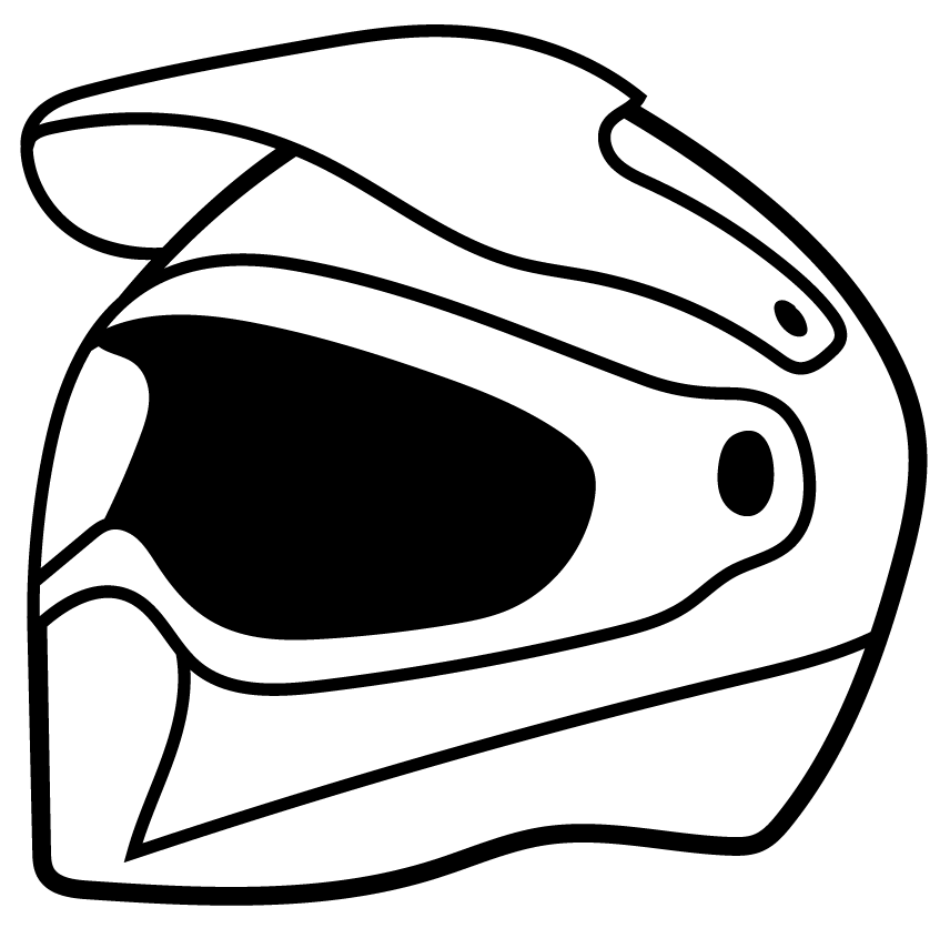
Wear an approved helmet. Riding in this vehicle without wearing an approved helmet increases the risk of serious injury. For example, a helmet reduces your risk of injury from head strikes with the vehicle or other objects even if there is no crash.
Approved helmets in the USA and Canada bear a U.S. Department of Transportation (DOT) label. Approved helmets in Europe, Asia, and Oceania bear the ECE 22.05 label. The ECE mark consists of a circle surrounding the letter E, followed by the distinguishing number of the country which has granted approval. The approval number and serial number will also be displayed on the label.
Use shatterproof goggles or a shatterproof helmet face shield. Such protective eyewear may reduce the risk of foreign material getting in your eyes and help prevent loss of vision.
Polaris recommends wearing approved Personal Protective Equipment (PPE) that have markings indicating they are designed to standards such as:
VESC 8
V-8
Z87.1
CE

Additional protective clothing and gear that may be appropriate for your riding conditions includes:
Always wear shoes when operating. Consider wearing sturdy over-the-ankle boots suitable for the terrain you will be riding in.
Full-finger gloves can protect against wind, sun, cold, and objects. Choose gloves that fit snugly and allow fingers to move freely and grip on the steering wheel or hand holds.
Consider long sleeves and long pants to help protect arms and legs.
Long-term exposure to wind can cause permanent hearing loss. Properly worn hearing protective devices such as earplugs can help prevent hearing loss. Check local laws or the rules of the riding area you are in before wearing hearing protection to make sure its use is permitted.
Always stay completely inside the vehicle and hold the steering wheel or hand holds. Body parts outside of the vehicle can be struck by passing objects or crushed during a rollover. Do not put any part of your body outside of the vehicle for any reason. Do not hold onto the ROPS frame or put any part of your body on the door/net.
Riding in this vehicle without closed and latched cab doors or nets increases the risk of serious injury or death in the event of an accident or rollover. Always make sure all cab doors/nets are closed and latched while riding in this vehicle.
Be sure riders pay attention and plan ahead. If you think or feel the vehicle may tip or roll, reduce your risk of injury:
Keep a firm grip on the steering wheel or hand holds and brace yourself.
Do not put any part of your body outside of the vehicle for any reason.
This vehicle is not designed to carry unrestrained pets. An unrestrained pet can be thrown about and injure riders, even during normal operation. When transporting pets, use a pet crate suitable for off-road use that is secured to the vehicle.
Fuels such as gasoline can be extremely flammable. To reduce the risk of serious injury or death, never carry fuel or other flammable liquids on this vehicle. Rollovers, crashes, rough riding, or changes in elevation or temperature may lead to fuel spilling or vapor release from portable containers. Hot vehicle parts can cause fires, even after the vehicle is powered off.
Never exceed vehicle weight capacities. The vehicle’s maximum weight capacity (including riders, cargo, and accessories) can be found in the Specifications chapter. When more rider weight is added, cargo weight may need to be reduced to stay under the limit. Overloading the vehicle or carrying cargo improperly will cause changes in stability and handling, which could cause loss of control or an accident.
Secure cargo in the cargo box as far forward, centered and as low as possible. When cargo cannot be positioned and secured in this way, operate with extra caution. Unsecured cargo can strike and injure riders, affect vehicle handling, and result in loss of control.
The weight of riders and cargo changes vehicle braking, handling, and stability. To avoid loss of control, turn gradually, operate at slower speeds, and avoid rougher or steeper terrain.
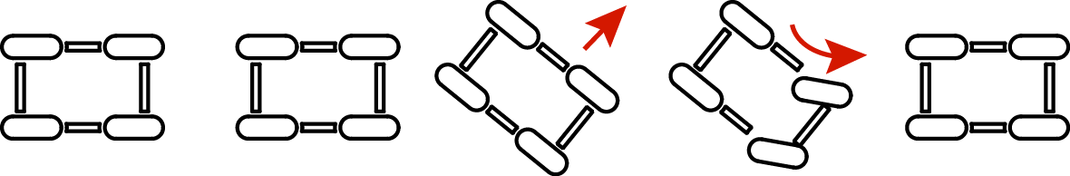
Drive Responsibly. This vehicle has higher ground clearance and other features to handle rugged terrain. It can be overturned in situations where some other vehicles may not. Abrupt maneuvers or aggressive driving, even on flat, open areas, can cause loss of control, rollovers, severe injury or death. To avoid loss of control and rollovers:

Avoid abrupt maneuvers, sideways sliding, skidding, or fishtailing, and never do donuts.
Slow down before entering turn.
Avoid hard acceleration when turning, even from a stop.
High speed off-road operation
Driving off-road
vehicles to test the limits of your skills or abilities can be very
dangerous to you, passengers, and bystanders. Basic skills for driving
a car, ATV, or other off-road vehicles do not equip drivers to safely
attempt high speed off-road operation. Develop your skill gradually
through training, practice, and experience with the various driving
modes of this vehicle and the terrain in which you are operating.
Always do a low speed reconnaissance run (prerun) to become aware
of anything you may encounter.
High speed off-road operation can lead to loss of control, crashes, or hard landings that can seriously injure occupants (even without rolling the vehicle or damaging it).
If you plan on using the vehicle for high speed, off-road competition, additional safety equipment may be necessary. Check the rules that apply to your competition.
Do not go over jumps — going airborne can lead to serious injury or death. Going airborne can cause loss of control, rollovers, or crashing into the ground and may damage the vehicle. Even without crashing, landings can be hard enough to cause any vehicle suspension to fully compress (e.g., bottom out). Serious injuries, including spinal injuries, can occur even if riders are properly harnessed, wearing helmets and the vehicle is not damaged and remains upright.
You may encounter slopes, "jumps", or other terrain features that could send the vehicle airborne, depending on your speed. These may be defectively designed, poorly maintained, or not suitable for this vehicle. Slow down, use extra care, and avoid going airborne. Never take this vehicle over jumps.
Watching someone else go over a jump or go airborne does not mean you can safely do so. Polaris cannot determine whether any jump you may encounter is appropriate for this vehicle. Any jump, even a small one, could be poorly maintained, designed, or not suitable for this vehicle and may cause serious injury or death.

Plan for hills, rough terrain, ruts, and other changes in traction and terrain. Proceed slowly and with extra care on unfamiliar terrain. Avoid paved surfaces. Sudden changes in terrain such as holes, depressions, banks, softer or harder ground, or other irregularities may cause loss of control or rollover. Give yourself time to react to rocks, bumps, or holes that may be hard to see. Operating in deep snow or tall grass may make it harder to see obstacles.
If you cannot go around an obstacle, such as a fallen tree or a ditch, stop the vehicle in a safe place. Get out to inspect the area thoroughly. Look from both your approach side and exit side. If you are reasonably confident you can continue safely, choose the path that will allow you to go straight over the obstacle to minimize the vehicle tipping sideways. Go only fast enough to maintain your momentum, but still give yourself plenty of time to react to changes in conditions. If there is any question about your ability to maneuver safely over the obstacle, you should turn around if the ground is flat and you have the room, or back up until you find a less difficult path.
Abrupt application of the accelerator pedal can cause the tires to lose traction, reducing control of the vehicle and increasing the possibility of an accident, especially while on sloped terrain or while crossing obstacles such as rocks or logs.
Avoid Operating on Public Roads (Paved or Otherwise). This vehicle does not have highway safety features that on-road vehicles may have (air bags, anti-lock brakes, stability control, etc.). If another vehicle collides with you, the likelihood of a serious injury or death may be greater. Also, you may not be able to avoid a crash or rollover if you make sudden or abrupt maneuvers such as swerving or emergency braking.
While it may be legal locally to drive on some public roads in specific parts of the country, your vehicle was not designed or certified as an on-road motor vehicle. Polaris does not support public road use except as may be necessary to cross roads designated for connecting off highway trail segments. If you must drive on-road, drive slowly and defensively. Your vehicle may lack the features needed to comply with state or local laws that permit limited public road use. Modifications you make to your vehicle to meet these requirements may void the vehicle warranty. In addition, refer to tire manufacturer's instructions or limitations for on-road operation, including speed limits and premature tire wear.
Improperly operating on hills can cause loss of control, rollover, or accident, which can lead to serious injury or death. Use extra care when operating on hills. Plan for rough terrain, ruts, and other changes in traction and terrain.
Driving up hills
Check the terrain before
ascending a hill and make sure it is not too slippery or loose. Engage
all-wheel drive for hills. Drive straight uphill, keeping speed and
accelerator steady. Avoid steep hills which can cause the vehicle
to overturn.
Recovering from stalling on a hill
If the
vehicle loses forward speed, apply the brakes gradually and stop.
Do not attempt to turn the vehicle around. Instead, allow the vehicle
to slowly roll straight downhill. Apply light brake pressure to control
speed.
Overtopping a hill
Slow down when you reach
the crest of a hill. Never blindly go over the crest of a hill or
a drop off at high speed. An obstacle, a sharp drop, or another vehicle
or person could be on the other side of the hill.
Driving down hills
Check the terrain before
descending a hill and make sure it is not too slippery or loose. Engage
all-wheel drive and proceed slowly, applying the brakes lightly. Never
descend a hill with the transmission in neutral or if the motor is
turned off.
Avoid side hilling (riding across slopes)
If unavoidable, proceed slowly and with extra caution. Avoid obstacles
and changes in terrain that could cause the vehicle to tip or slide.
If it feels like the vehicle begins to tip or slide, immediately turn
downhill.
Riding near wooded areas or brush
Use extra
caution when operating near trees, particularly when operating on
narrow trails. Tree branches or brush can be driven into the cab striking
or stabbing occupants.
Riding in snow
Always keep the brake and
accelerator pedals free of snow and ice. Apply the brakes frequently
to prevent ice or snow accumulation on the brake pads which can reduce
brake performance.
Riding on ice
Never operate the vehicle on
a frozen body of water unless you have verified that the ice can support
the weight of the vehicle. Severe injury or death can result if the
vehicle falls through the ice.
Riding in water / Falling into water
Operating
through deep or fast-flowing water can cause loss of traction, loss
of control, overturning, or being swept away in water. You can be
seriously injured or killed from entrapment and drowning. Never operate
the vehicle in fast-flowing water or in water that exceeds the floor
level of the vehicle. Avoid sharp drop-offs and large rocks. Choose
a path that provides an entrance and exit point with gradual inclines.
Wet brakes may have reduced stopping ability. After leaving water,
test the brakes. Apply them lightly several times while driving slowly.
The friction will help dry out the pads.
Riding on sand dunes
Use extra caution when
operating on or near dunes. Be alert for changes in terrain. Never
blindly go over the crest of a hill or a drop-off at high speed. An
obstacle, a sharp drop, or another vehicle or a person could be on
the other side of the hill.
Riding in low-visibility conditions
Use extra
caution and drive slowly in conditions of reduced visibility such
as fog, rain, and darkness.
Plan ahead to avoid the need for evasive maneuvers, such as swerving. Hitting an obstacle — including wildlife — you are not ready for can be dangerous. Choosing to swerve instead can be even more dangerous because it can lead to loss of control, rollover, or collisions.
When operating in areas with possibility of wildlife appearing in your path, plan ahead to avoid swerving for animals if doing so could result in collisions or rollovers. Go slowly or avoid driving during seasons or times of day when animals such as deer are more likely to cross your path without warning.
Avoid Collisions With Other Vehicles
When
following another vehicle or operating in the same area as others,
keep a safe distance to avoid collisions. Allow extra space when sight
distances are limited by dust, snow, curves, hills, or other conditions.
Plan ahead to avoid having to swerve or leave the trail to avoid a
collision.
On trails, be prepared to make space for other vehicles to pass. If you need to stop on a trail, move your vehicle to the edge of the path to allow others to pass safely.
Correct a skid by turning the steering wheel in the direction
of the skid.
Never apply the brakes during a skid.
If the vehicle begins to slide downhill or you feel it may tip, turn downhill immediately and stop. Maneuver slowly and carefully until you can drive straight downhill.
Do not continue driving if your vehicle may be damaged or if
you were in a crash or rollover.
Operating the
vehicle while damaged or after a crash or rollover can cause loss
of control, rollover, or accident, which can lead to serious injury
or death. If you cannot safely transport the vehicle on your own,
contact a recovery and towing service.
After any crash, rollover, or other accident, have a Polaris dealer inspect the vehicle for possible damage, including seat belts, ROPS, brakes, suspension, electrical components, and steering systems.
Be prepared in case your vehicle becomes damaged or disabled, especially in remote areas. Consider in advance how to get help and stay safe until it arrives whenever you ride.
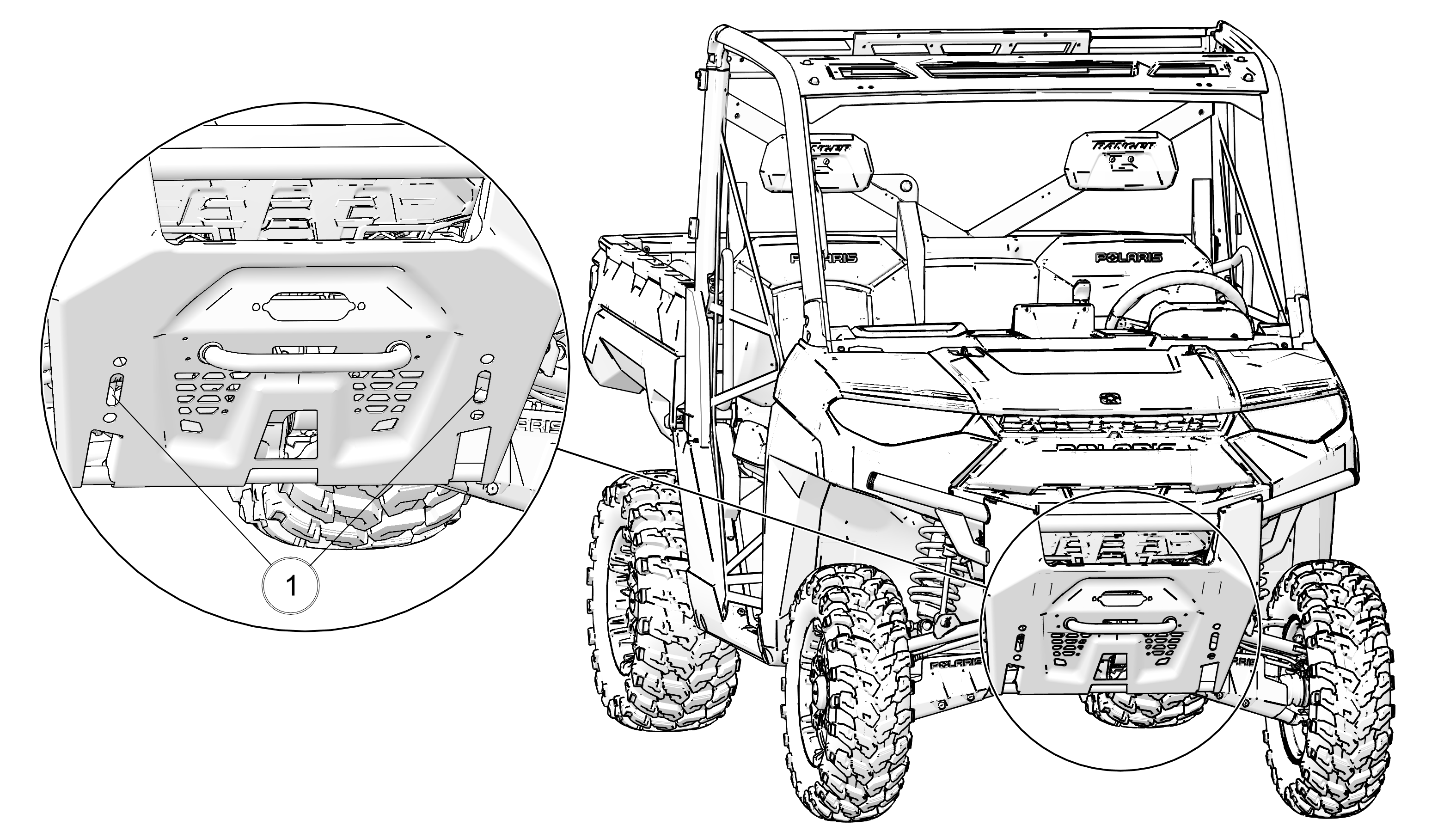
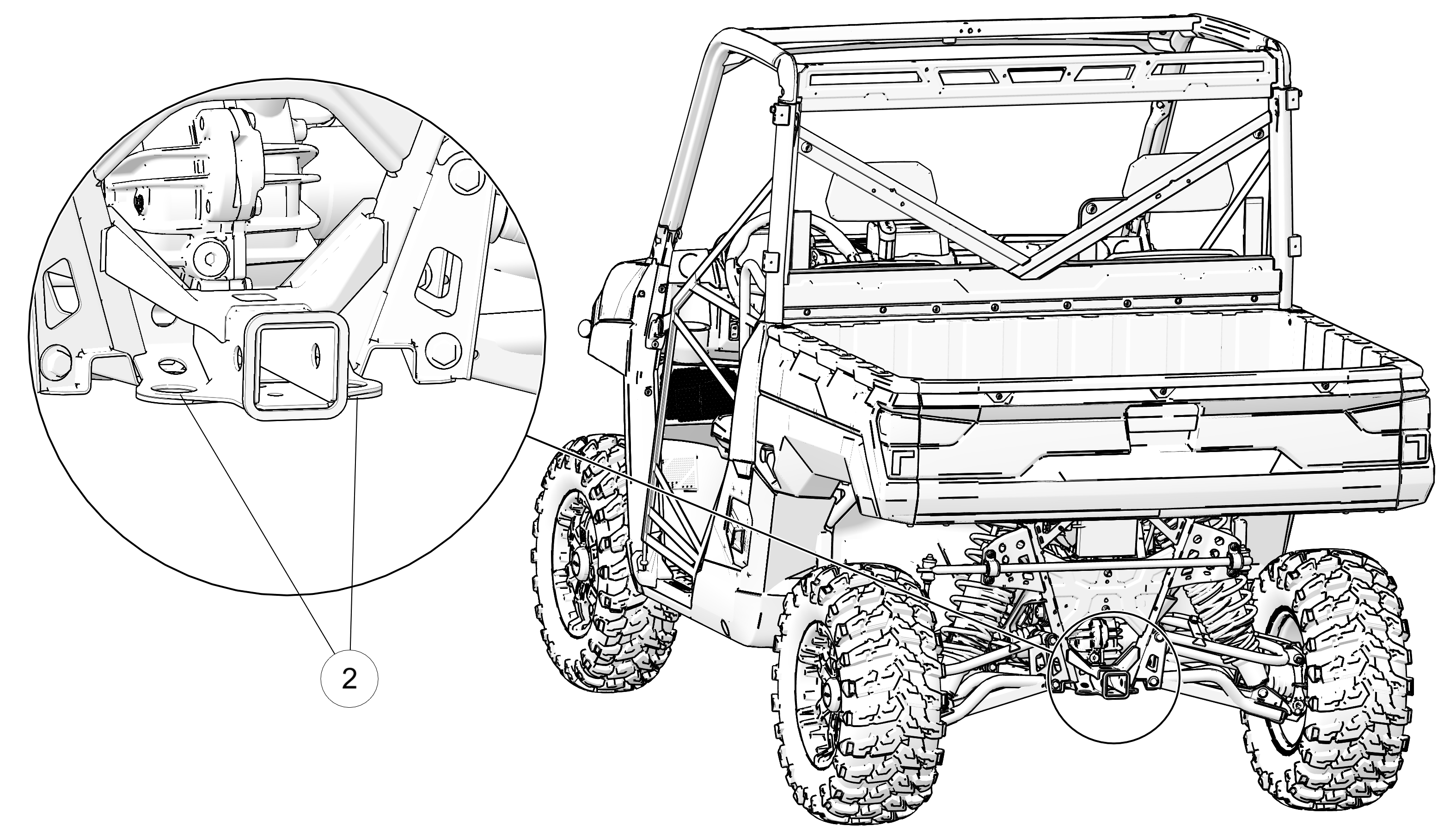
There is a recovery tow point at the front and back of the vehicle
to attach a winch or strap.
Use these points at
the front1 or rear2 of the vehicle to recover this
vehicle if it is stuck, to pull it onto a tow truck, trailer, or to
use this vehicle to recover another vehicle. These points are for
emergency recovery only and are not for towing vehicles to another
location.
Improper recovery may lead to loss of control or vehicle damage. Only attach straps to specified locations. Do not attach to any other point on the vehicle. Only recover a vehicle of equal or lesser size and weight. When recovering a disabled vehicle, place the disabled vehicle’s transmission in neutral. Do not move a disabled RANGER faster than 10 mph (16 km/h).
Vehicle rollaway can cause serious injury or death. This vehicle can roll whenever the gear selector is not in the PARK (P) position. Always shift to PARK (P) when stopping the motor or leaving the vehicle. When leaving the vehicle on an incline is unavoidable, use extra care. If leaving the vehicle unattended, block the rear wheels on the downhill side and keep children, pets, and others away from the gear selector.
Before switching to reverse, use extra care to make sure the area is clear of people or obstacles. When it’s safe to proceed, back slowly.
After operation, inspect the vehicle for damage and debris to make sure the vehicle can be safely stored and operated again. Some things to inspect include:
Debris such as mud/grass near the charge port or cooling system
Damage to the suspension, steering, or any other part of the vehicle
Tire condition, such as tread and sidewall damage
Shock absorber assembly condition
This vehicle uses an electric drive system powered by a high-voltage battery pack. There are additional safety precautions for charging, operating, and maintaining the vehicle.
Failure to follow these precautions may cause electric shock, fire, serious injury, or death.
Select an appropriate
power source
The circuit used to charge the vehicle
must:
Have GFCI protection
Be rated for at least 15 amps
Not have other electrical loads
The circuit must also be appropriate for EV charging. Make sure that it is properly grounded and compliant with all local codes and ordinances. If there is doubt as to whether the circuit is appropriate, check with a qualified electrician.
Inspect
charging equipment before each use
Make sure the
electric vehicle supply equipment (EVSE) connections at the outlet
and vehicle charge port are free from dirt and debris. Remove debris
with compressed air while wearing eye protection or by rinsing with
low pressure water. Do not use tools (e.g., screwdriver) to remove
debris.
Before charging, inspect charging components for damage:
Outlet
EVSE wall plug
EVSE cables
EVSE vehicle plug (J1772)
Vehicle charge port
Properly connect the EVSE
Connect the EVSE wall plug directly into the outlet. Never use any device between this connection (e.g., extension cords, grounding adapters, multi-outlet splitters or power strips, surge protectors, timers, or smart home adapters).
Position the EVSE cable to keep it from being driven over, stepped on, tripped on, strained, or otherwise damaged.
Insert the EVSE charging plug into the charger socket until you hear an audible “click” sound.
Additional steps for charging in wet conditions
With the included portable EVSE, the vehicle can be charged in wet
conditions if the following precautions are taken:
Make sure the EVSE does not become submerged while charging. If the EVSE was submerged while not charging, let it completely dry before using to charge.
When connecting to an outdoor power source in wet conditions, only use a weather-resistant outlet (marked with "WR") with a weatherproof while-in-use cover in the closed position.
Only charge using EVSE
The 12V battery is automatically
charged by the high-voltage battery as needed and never requires external
charging (e.g., using a trickle charger). If you think there may be
a problem with the 12V battery, replace the battery or see your dealer.
To avoid serious injury or death, never attempt to “jump
start” this vehicle or connect an external power source directly
to the 12V battery. This will not add charge to the high voltage battery.
If the vehicle is unresponsive, only charge the high voltage battery
using an EVSE.
Using other EVSEs
Polaris
recommends using the EVSE provided with the vehicle or other Polaris-approved
EVSEs. Other EVSEs may be compatible with this vehicle. Be sure to
follow the instructions for any other EVSE used.
Use extra care when selecting your direction of travel
Failure to select and know your direction of travel can
result in the vehicle moving in the opposite direction of what you
intend. Each time you enter the vehicle and before you start moving,
press the Direction Selector Switch in the forward position (F) to
go forward or the reverse position (R) to go rearward. Check the position
of the Direction Selector Switch to verify your selection before pressing
the accelerator pedal.
Avoid changing the Direction Selector
Switch while in motion
If the Direction Selector
Switch is changed while the vehicle is traveling above 5 mph
(8 kph), the motor
will be de-energized. Once vehicle speed is below 5 mph
(8 kph) and the
accelerator pedal is released, the vehicle will respond to the accelerator
pedal and move in the selected direction.
Use the brake pedal
The regenerative braking in this vehicle does not
allow one-pedal driving (i.e., only using the accelerator pedal).
Like most other vehicles, driving this vehicle requires the use of
the brake pedal.
Do not store items under the storage bin
beneath the seat
Do not store items underneath
the storage bin (located under the seat) and on top of the 12V battery.
They could contact the battery terminals.
Check for damage
to high-voltage components after an accident
Crashes,
rollovers, and other impacts can damage the high-voltage battery pack
and create a risk of electric shock and fire. The vehicle will indicate
that it detects damage through warning lights in the instrument cluster
or the Ride Command display, if equipped.
There may
also be damage that the vehicle does not detect. After an accident,
remove the service disconnect loop (see Disconnecting High Voltage Power) and inspect
the high-voltage system (e.g., battery, cables, connections, covers).
Other signs of damage may include abnormal sounds from the vehicle.
If the high-voltage system is damaged, contact your dealer
and do not use the vehicle.
Avoid fire from damaged vehicles
If the vehicle is damaged, shift the vehicle to Neutral
(N) and move it outside and away from anything that can burn, if possible.
If there are signs of a fire, get away from the vehicle and contact
fire emergency responders. Have first responders use a Class D fire
extinguisher on electrical components.
Immediately respond to a thermal runaway
If
the vehicle detects a thermal runaway, stop and have all occupants
move away from the vehicle immediately. Then, contact fire emergency
responders. A thermal runaway is an extremely rare event caused by
a malfunction or damage to the electronic powertrain system. A thermal
runaway occurs when the high-voltage battery rapidly increases in
temperature causing additional chemical reactions that continue to
increase temperature. This could ultimately result in fire or explosion.
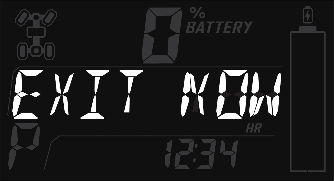
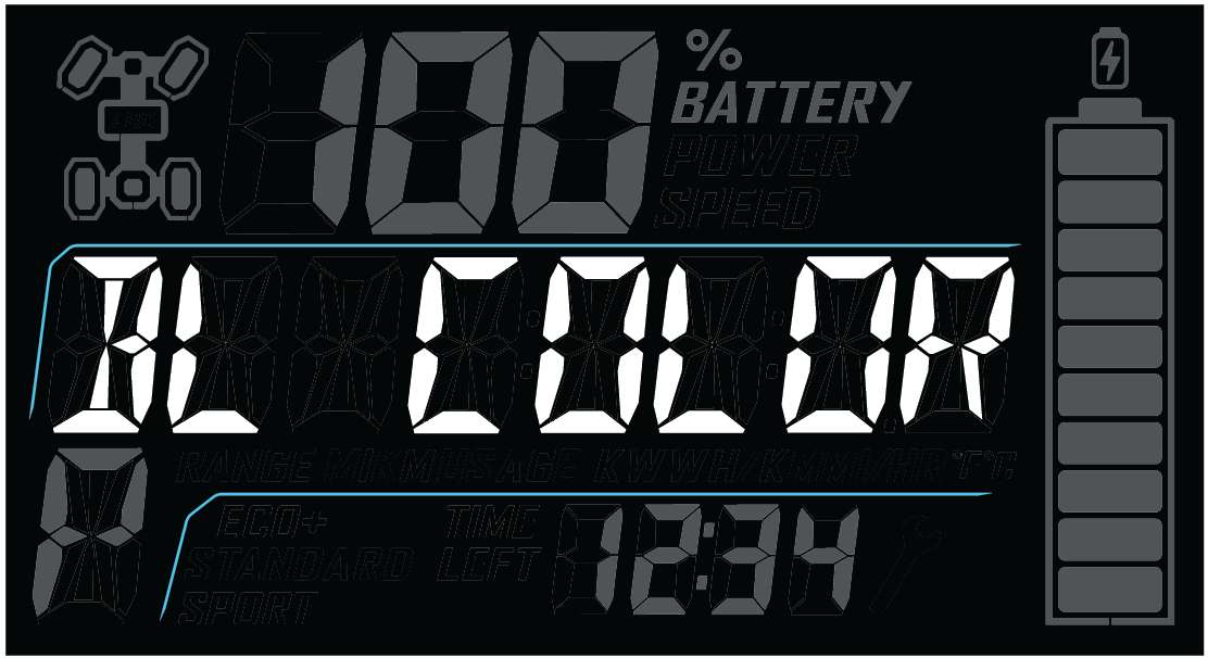
The vehicle will indicate it detects a thermal runaway using the following prompts:
On the Instrument Cluster
The text will scroll
the phrase “DANGER EXIT NOW FIRE” and the MIL, AWL,
Over Temperature, and high-voltage Battery Pack warning lights will
flash. See Indicator Lamps for
details on Indicator Lamps.
On the Ride Command Display (if equipped)
A
red banner will appear on the display screen prompting you to exit
the vehicle.
Auditory Alarm
The vehicle will provide an auditory alarm for as long as the vehicle
detects a thermal runaway.
Loss of Motor Power
The vehicle will not respond to throttle input and
there will be no regenerative engine braking.
No Battery Charge Indicated
The high-voltage
battery pack will be disconnected from the motor. Vehicle displays
will indicate a state of no charge
Do not perform maintenance
on high-voltage components
Never try to service
high-voltage components. There are no user-serviceable components
to the high-voltage system. Always have a qualified technician service
high-voltage components.
Do not touch any high-voltage components. High-voltage wiring is orange. Other high-voltage components are labeled.
Do not tamper with or attempt to open the charging equipment or high-voltage battery pack.
Do not remove or dispose of the high-voltage battery pack. Contact an authorized dealer for replacement and disposal.
Warning labels have been placed on the vehicle for your protection. Read and follow the instructions of the labels on the vehicle carefully. If any of the labels depicted in this manual differ from the labels on your vehicle, always read and follow the instructions of the labels on the vehicle.
If an informational or graphic label becomes illegible or comes off, contact your Polaris dealer to purchase a replacement. Replacement safety labels are provided by Polaris at no charge. The part number is printed on the label.
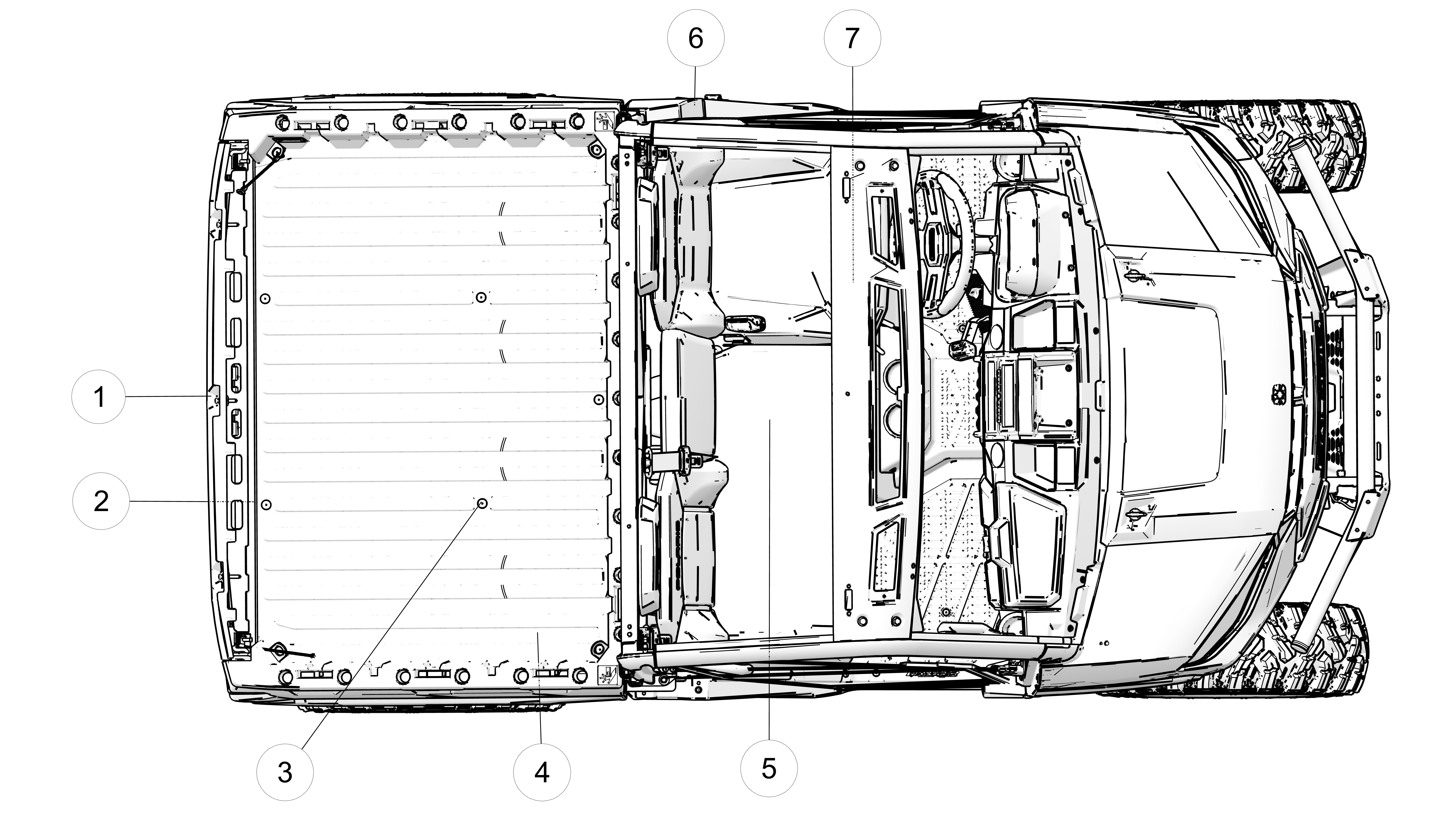
1 Trailer Weight Maximums (on hitch receiver)
2 Load/Passenger/Tire Pressure Warning
2 Maximum Payload Warning
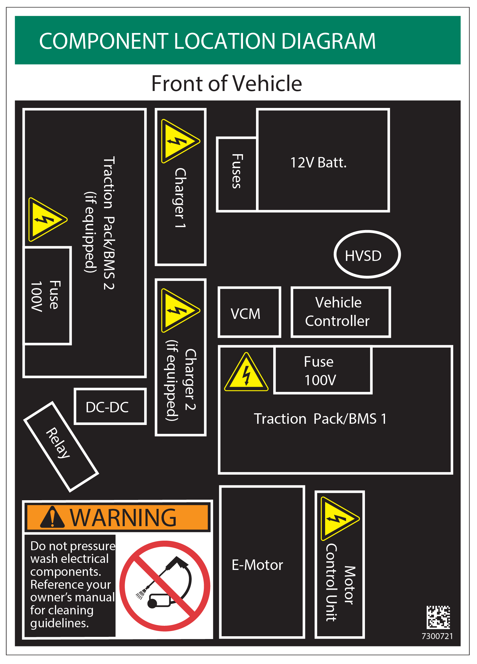
3 Component Diagram / Power Wash Warning (under cargo box)
4 Fuel Transport Warning
5 Service Disconnect Warning (under seat)
6 EVSE Charge Port Warning (inside compartment)
7 Driver Information Warning (on top ROPS bar)
WARNING
Improper vehicle use can result in SEVERE INJURY or DEATH.
Be Prepared
Fasten seat belts.
Wear an approved helmet and protective gear.
ALWAYS use vehicle cab nets and/or doors.
Each rider must be able to sit with back against seat, feet flat on the floor, and hands on steering wheel or hand holds. Stay completely inside the vehicle.
Drive Responsibly
Rollovers have caused severe injuries and death, even on flat, open areas.
Avoid loss of control and rollovers:
Avoid abrupt maneuvers, sideways sliding, skidding or fishtailing, and never do donuts.
Slow down before entering a turn.
Avoid hard acceleration when turning, even from a stop.
Plan for hills, rough terrain, ruts, and other changes in traction and terrain.
Avoid paved surfaces.
Avoid side hilling (riding across slopes).
Be Sure Riders Pay Attention and Plan Ahead
If you think or feel the vehicle may tip or roll, reduce your risk of injury:
Keep a firm grip on the steering wheel or hand holds and brace yourself.
Do not put any part of your body outside of the vehicle for any reason.
Require Proper Use of Your Vehicle
Do your part to prevent injuries:
Do not allow careless or reckless driving.
Make sure operators are 16 or older with a valid driver’s license.
Do not let people drive or ride after using alcohol or drugs.
Do not allow operation on public roads (unless designated for off-highway vehicle access) - collisions with cars and trucks can occur.
Do not exceed seating capacity: 3 occupants.
SCAN CODE FOR PRODUCT AND SAFETY INFORMATION. FOLLOW ALL INSTRUCTIONS AND WARNINGS

NOTICE
High-Voltage Service Disconnect Located
Under Seat Bin
EMERGENCY ONLY
Remove seat bin. Locate service
disconnect. Cut wire loop where indicated.
SERVICE
Remove seat bin. Locate service disconnect.
Remove by grabbing plastic housing. Do not pull wire loop.
WARNING
Before servicing your vehicle’s
electrical system, ALWAYS activate the service disconnect.
Warning
Keep charge
port covers closed unless charging. Do not use tools to clean terminals.
Remove debris with a cloth or low pressure water.
WARNING
Do not pressure wash electrical
components. Reference your owner’s manual for cleaning guidelines.
WARNING
The Maximum Payload Warning label is located on the cargo box.
| RANGER XP KINETIC | Never Exceed | If Total Payload Exceeds |
|---|---|---|
| PREMIUM | 30 mph (48 kph) | 550 lbs (249 kg) |
| ULTIMATE |
NOTICE
To avoid transmission damage, only shift gears when vehicle is stationary. When the vehicle is stopped, place shifter in PARK position.
| TRAILER MAX. WEIGHT | 2500 lbs. (1134 kg) |
| HITCH MAX. VERTICAL WEIGHT | 250 lbs. (114 kg) |
WARNING
NEVER carry fuel or other flammable liquids on this
vehicle.
Failure to follow this instruction
could lead to serious burn injuries or death.
Part Number: 7186122 (English) and 7186122–F (French Canadian)
WARNING
Never carry passengers in cargo box.
Passengers can be thrown off. This can cause serious injury or death.
If total payload is greater than 500 lbs. (227 kg), the vehicle must be operated in LOW range.
IMPROPER TIRE PRESSURE OR OVERLOADING CAN CAUSE LOSS OF CONTROL RESULTING IN SERIOUS INJURY OR DEATH.
Reduce speed and allow greater distance for braking when carrying cargo.
Overloading or carrying tall, off-center, or unsecured loads will increase your risk of losing control. Loads should be centered and carried as low as possible in box.
For stability on rough or hilly terrain, reduce speed and cargo.
| RANGER XP KINETIC | ULTIMATE | PREMIUM |
| MAXIMUM CARGO BOX LOAD | 1250 lbs. (567 kg) | |
| MAXIMUM CARGO LOAD WHEN TRAILER TOWING | 600 lbs. (272 kg) |
|
| TIRE PRESSURE IN PSI (KPa) | FRONT 12 (83) REAR 14 (97) |
|
|
MAXIMUM WEIGHT CAPACITY
INCLUDES WEIGHT OF OPERATOR, PASSENGERS, CARGO AND ACCESSORIES |
1500 lbs. (680 kg) | |
| Read Operation and Maintenance Manual for more detailed loading information. | ||
Your Polaris electric vehicle (EV) is equipped with an all-electric motor powered by a high-voltage battery pack that can be charged for re-use without the need for fossil fuels or other fluids, filters, and ignition devices associated with internal combustion engines.
The advantages and limitations of EVs should be considered before operating this vehicle. Read the following sections for information on best practices:
Charging Best Practices(See Good Charging Habits)
Weather Best Practices(See Charging in Extreme Ambient Temperatures)
Vehicle Range(See Factors that Influence Vehicle Range)
Long-term Storage(See Ideal Conditions for Storage)
Leave the vehicle plugged in between frequent uses
The vehicle operates best when charged regularly. You do not need
to run your battery pack low before charging again as there is
no benefit in letting batteries run low. Instead of waiting until
the State of Charge (SoC) is near empty to recharge the battery pack,
take every opportunity to recharge during downtime.
Charge in moderate temperatures
Charging
in extreme temperatures may limit the rate of charge the battery pack
receives. See Charging in Extreme Ambient Temperatures for details.
Charge during “off-peak” hours
Peak hours are when electricity demand is the highest amount per
kWh. If charging at home, charging the vehicle during off-peak hours
will keep charging costs low. Commonly, off-peak hours are at night
when electricity consumption is low. Check with your electric
companies as some may offer discounts during off-peak hours.
Follow the procedure below to charge your vehicle.
Stop the vehicle on a flat surface.
Set the gear selector to PARK (P).
Turn the key switch to OFF.
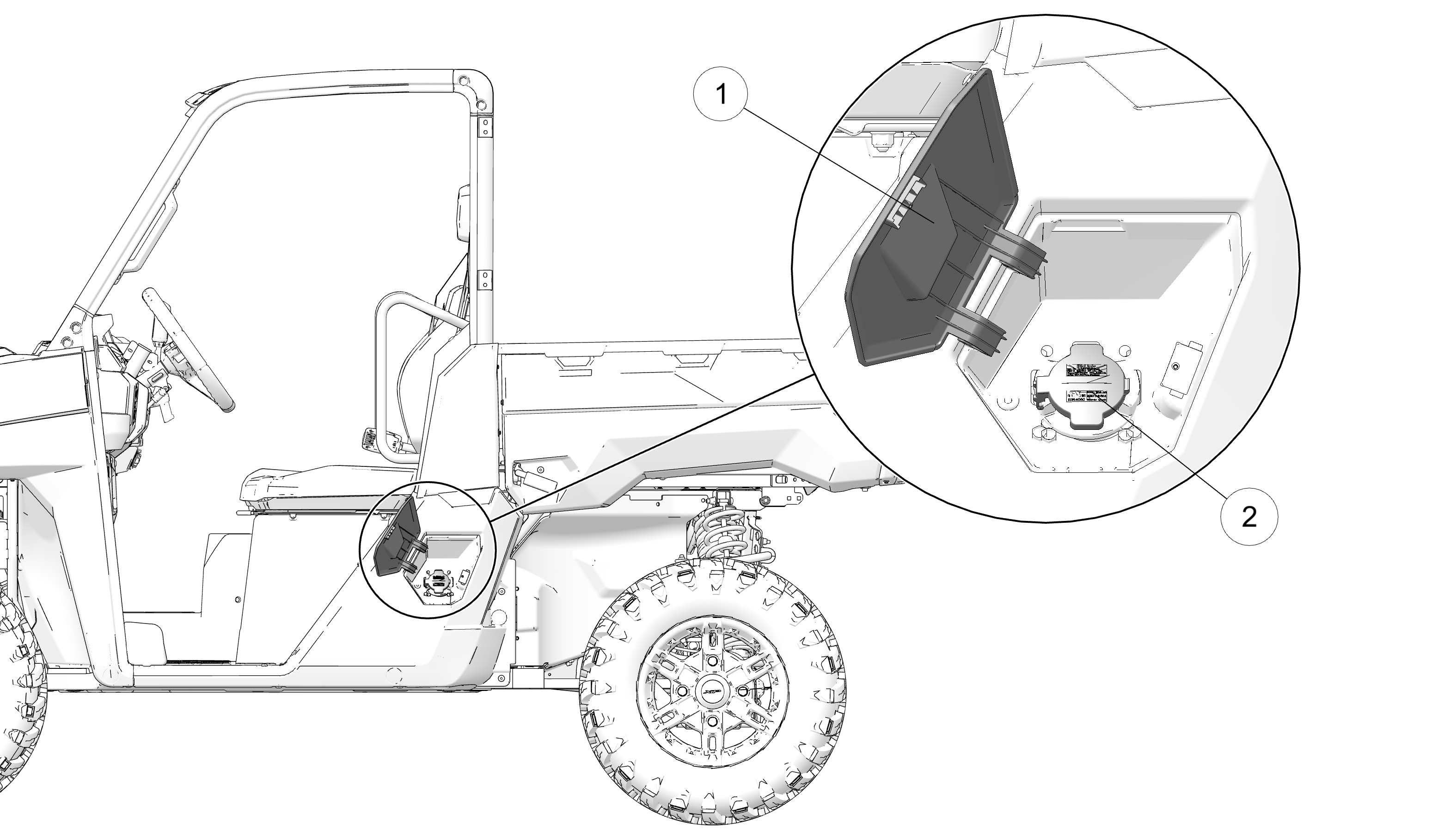
Open the charge compartment door 1.
Open the charge port cover 2.
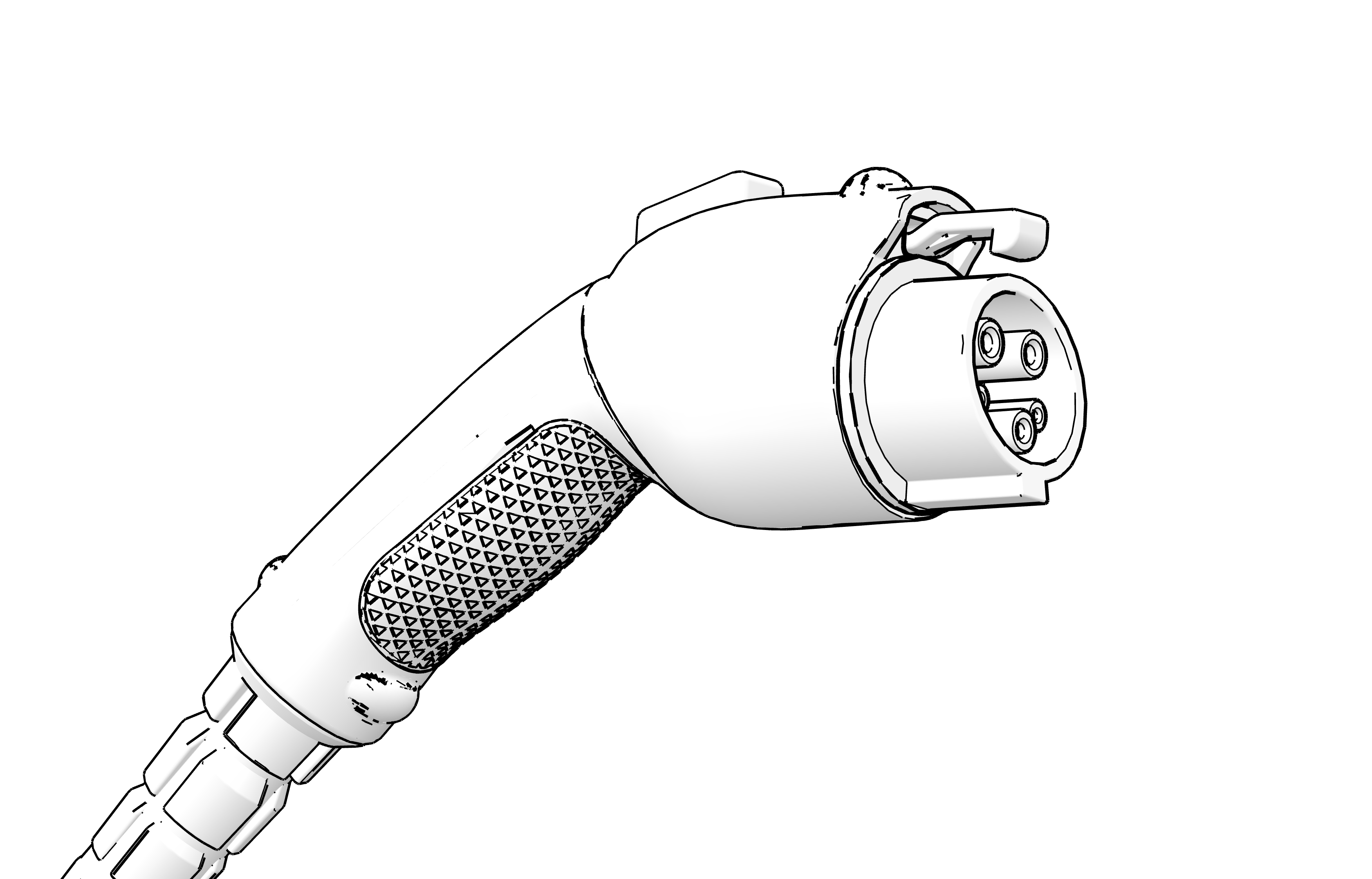
Insert the EVSE charging plug into the charger socket until you hear an audible “click” sound. Once the vehicle begins charging:
The vehicle display will switch to the charging screen.
The vehicle will charge continuously until fully charged.
The vehicle will not be driveable while EVSE charging plug is connected.
Charge performance may vary as a result of ambient temperatures affecting internal battery temperature. See Charging in Extreme Ambient Temperatures for details.
Once ready to resume operation, remove the EVSE charging plug.
Reattach the charge port cover and close the charge compartment door.
Electric Vehicle Supply Equipment (EVSE) is required for charging electric vehicles. The EVSE supplied with your vehicle is a J1772 style port that is Level 1 (120V) and Level 2 (240V) compatible.
Onboard Chargers (OBCs) convert AC power to DC voltage that charges the high-voltage battery pack on your vehicle. Electric vehicles can be equipped with different onboard chargers with varying charge rates. For example, a 6 kW onboard charger will charge up to twice as fast as a 3 kW onboard charger when connected to an EVSE with kilowatt output at or above the charger rating.
The high-voltage battery pack carries the energy necessary to operate your vehicle. If you believe there is an issue with the high-voltage battery pack, do not attempt to service. Bring directly to your dealer or other qualified person.
Your vehicle’s high-voltage battery pack is equipped with a Battery Management System (BMS) that monitors the condition of the battery and optimizes charging. Under certain conditions, the BMS will act to prevent damage to the battery, including stopping or slowing the flow of charge.
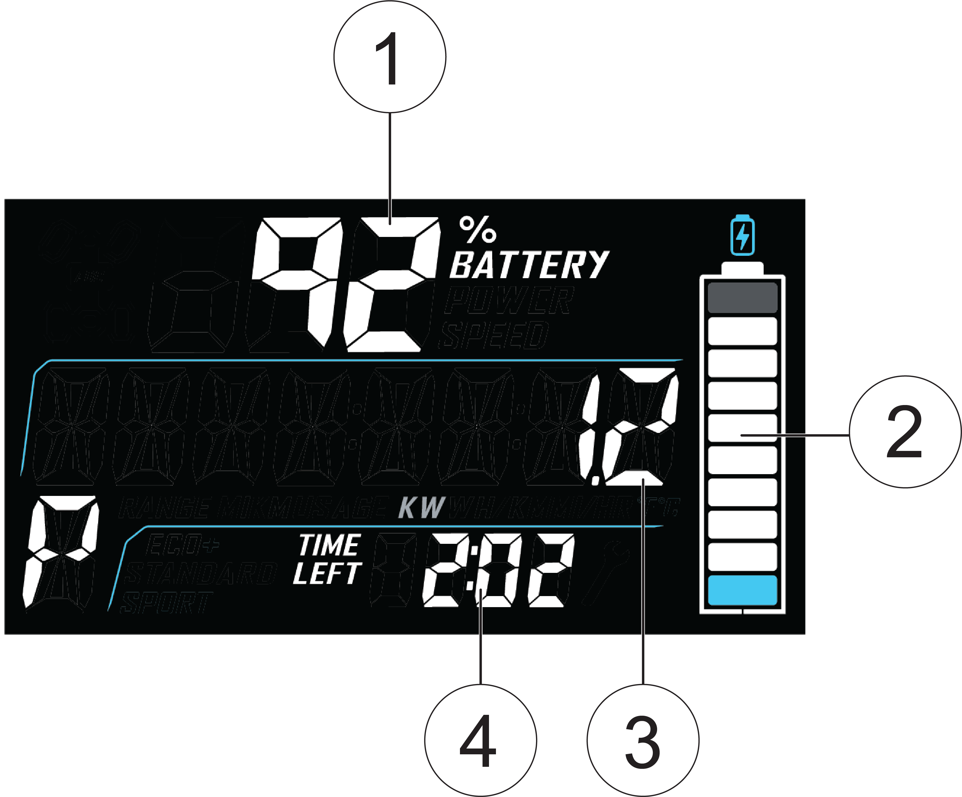
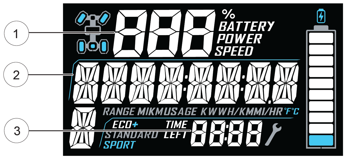
Instrument Cluster
When charging the vehicle, the State of Charge (SoC) will be displayed on the instrument cluster and the Ride Command Display (if equipped). Status indicators include:
1 State of Charge (%)
2 Battery icon
3 Rate of charge (in kW)
4 Time until SoC reaches 100%
Accent Light Bar
When the accent light switch (see Accent Light Switch) is in the ON position and the
vehicle is charging, the accent light bar 1 at the front
of the vehicle will pulse as the battery pack charges. Sections of
the accent light bar will remain illuminated as a visual representation
of State of Charge (SoC) status. When the accent light bar is fully
illuminated, the vehicle has reached 100% SoC.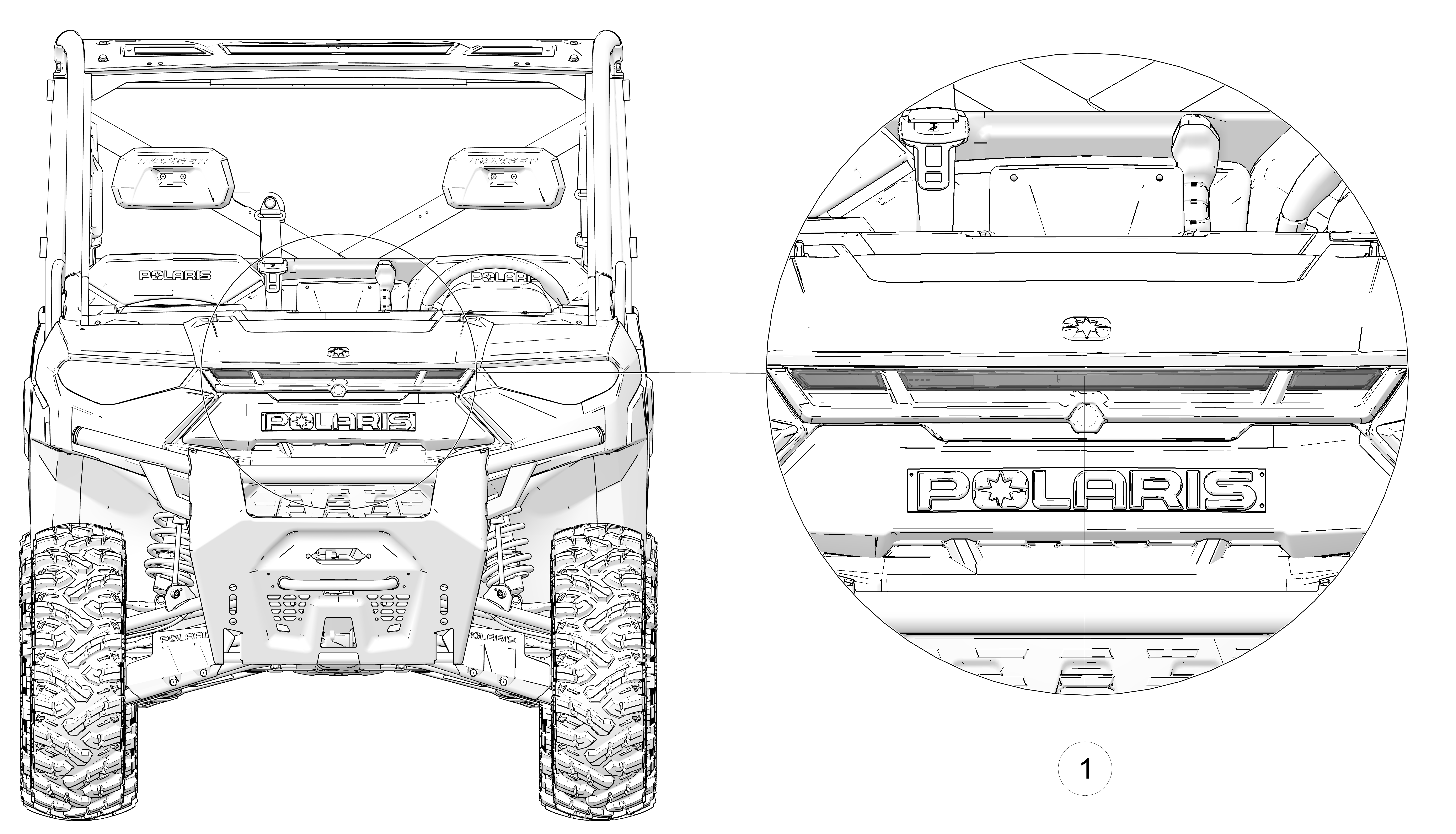
Your Polaris Electric Vehicle (EV) can receive a charge from multiple kinds of power sources, including:
120V home wall outlet
240V home wall outlet
J1772 Level 1 (120V) public charging stations
J1772 Level 2 (240V) public charging stations
Type I electrical outlet (Australia and New Zealand)
Not all power sources are equal with regard to charge time. For example, a wall circuit with 120V, 15 amperage service will have a longer charge time than 240V, 40 amperage service.
See the table below for charge time reference. Be sure to understand the voltage service options in your home when charging from home. Consult the Polaris website or your dealer for onboard charger accessory options to reduce charge time.
| Model | Premium | Ultimate | ||
|---|---|---|---|---|
| Battery Pack | 14.9 kWh | 29.8 kWh | ||
| Power Source | 120V Outlet | 240V Outlet | 120V Outlet | 240V Outlet |
| 3 kW Onboard Charger | 10 Hours* of Charging (0-100%) |
5 Hours* of Charging (0-100%) |
N/A | N/A |
| 6kW Onboard Charger | N/A | N/A | 20 Hours* of Charging (0-100%) |
5 Hours* of Charging (0-100%) |
| *All charge times shown are approximate | ||||
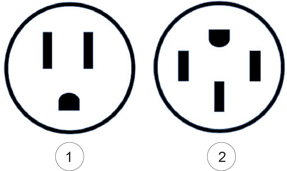
Power Outlet Types
The EVSE charger supplied with your vehicle includes two attachments
for compatibility with 120V and 240V outlets.
1 NEMA 5-15 (120V)
2 NEMA 14-50 (240V)
Power Outlet Types
(Australia and New Zealand)
The EVSE charger
supplied with your vehicle is compatible with Type I electrical outlets.

Your EV is designed to withstand wet conditions such as rainfall, puddles, snow, or muddy terrain. However, submersion in water past the floor level or the use of high-pressure hoses on inner components will void the warranty and may cause faults or make the vehicle temporarily inoperable. If this happens, have a dealer inspect the vehicle and allow the vehicle components time to dry until the vehicle is operable again.
The high-voltage battery pack on your vehicle is equipped with automatic heaters that sense when the battery’s internal temperature is below 50° F (10° C). This allows your vehicle to operate normally in below-freezing conditions.
If the battery temperature falls below 50° F (10° C), the battery heaters activate when:
the vehicle is charging, or
the key switch is in the ON position
When the vehicle’s high-voltage battery pack has an internal temperature outside of the ideal range, the Battery Management System (BMS) will either slow the rate of charge or stop charging altogether until the battery pack temperature has returned to the ideal range. A warning will appear on the Ride Command display (if equipped) and instrument cluster when this occurs.
| Battery Pack Internal Temperature | Charge Performance |
|---|---|
| Above 122° F (50° C) | No Charge |
| 104° to 122° F (40° to 50° C) |
Reduced |
|
50° to 104° F (10° to 40° C) |
Normal |
| -13° to 50° F (-25° to 10° C) |
Reduced* |
| -39° F to -13° F (-40° C to -25° C) |
No Charge* |
| At or Below -40° F (-40° C) | No Charge |
| *This will be temporary. Allow several minutes for the battery pack heaters to warm up to the point where normal charge performance resumes. | |
The high-voltage battery pack internal temperature and State of Charge (SoC) can affect performance. A vehicle may experience reduced performance or become inoperable if levels fall outside of a certain range.
The chart below details conditions that may cause reduced performance or vehicle shutdown when the vehicle is not connected to an EVSE charger and power supply.
| Battery Pack Internal Temperature | State of Charge (SoC) | ||
|---|---|---|---|
| Less than 5% | Less than 15% | Greater than 15% | |
|
Below -22° F (-30° C) |
Vehicle will not operate. | Vehicle will not operate. | Vehicle will not operate. |
|
Greater
than -22° F (-30° C) |
Battery heaters inactive. Reduced performance. | Battery heaters* only active if battery temperature is below -4° F (-20° C). Reduced performance. | Allow several minutes for battery heaters* to warm up. Normal performance. |
|
Greater
than 50° F (10° C) |
Reduced performance. | Reduced performance likely. | Normal performance. |
|
Greater
than 131° F (55° C) |
Reduced performance. | Reduced performance. | Reduced performance. |
|
Greater
than 140° F (60° C) |
Vehicle will not operate. | Vehicle will not operate. | Vehicle will not operate. |
| *Battery pack heaters will not activate unless the key switch is in the ON position when vehicle is not connected to an EVSE charger and power supply. | |||
When estimating the distance your Polaris Electric Vehicle (EV) can travel in a single charge, be sure to take into account the following factors:
Terrain
Hill climbs, mud, and sand put more
demand on your vehicle.
Style of Driving
Sporty driving requires
more power than conservative driving.
Weather
Strong headwinds, slippery conditions,
or extreme ambient temperature can decrease driving range and performance.
Payload
Passengers, cargo, or towing places
more demand on your vehicle.
Tire Pressure
Low tire pressure causes increased
drag and demand on your vehicle.
Differential Used
2x4, 4x4, or high/low require
different levels of motor output and energy consumption.
Frequency of Starts and Stops
More energy
is used to accelerate to cruising speed than maintaining cruising
speed.
Accessories
Larger tires, cab heater, lighting,
and audio can increase energy draw from the high-voltage battery pack.
With low loads, smooth terrain, and a conservative driving style, vehicle range will approximate to the following:
| Model | Range (on flat ground)* |
|---|---|
| RANGER XP KINETIC Premium | Up to 45 mi. (72 km) |
| RANGER XP KINETIC Ultimate | Up to 80 mi. (129 km) |
| *Range estimates based on manufacturer data on typical customer driving usage and conditions. Actual range varies based on conditions such as external environment, weather, speed, cargo loads, rates of acceleration, vehicle maintenance, and vehicle usage. | |
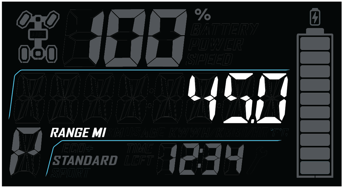
When the vehicle is powered on and not charging, the estimated remaining range (in miles or kilometers) can be found on the instrument cluster or Ride Command display (if equipped). See Mode Information Displays for details on instrument cluster navigation.
Your vehicle’s displayed range estimate is a calculation based on current State of Charge (SoC) and power consumption data gathered from previous rides. Calculations are made in real-time to provide adaptable estimates for varying driving styles.
Factors from previous rides that affect estimated driving range include:
Accelerator pedal inputs
Speeds
Terrain conditions
All batteries will degrade over time because of their chemical makeup. However, the Lithium-Ion batteries in RANGER XP Kinetic electric vehicles are designed to provide an extremely long, useful life. It could take up to 10 years or 10,000 miles to see a noticeable reduction in battery capacity and resulting range, expected to be about 5-10% at most.
Whenever your vehicle is moving and accelerator pedal is released or the brake is applied, the regenerative braking system recaptures surplus kinetic energy for the battery. The vehicle’s regenerative braking level is displayed on the instrument cluster. See Instrument Cluster for details.
For planned long-term storage of more than 30 days, follow the recommendations below to create the ideal storage conditions for your Polaris Electric Vehicle (EV) and maintain the lifespan of the high-voltage battery pack.
Store in Cool, Dry Areas
| Recommended Storage Temperature Range | 32° F to 113° F (0° C to 45° C) |
Store When State of Charge (SoC) is at 60%
Putting your EV into storage with 100% charge is not recommended,
as it may accelerate battery cell aging. Instead, operate the vehicle
until SoC has fallen to 60% (or charge until 60% is reached), then
place the vehicle in storage.
Check monthly to make sure State of Charge (SoC) does not fall
below 30%
While in storage, the SoC will gradually
drain. Check the SoC monthly to ensure it has not fallen below 30%.
If SoC is below 30%, charge back up to 60%.
24-Hour Charge Before Next Use
When the storage
period has ended, charge the vehicle for 24 hours before initial use.
This will allow enough time for optimal battery cell balance to be
restored.
Some Polaris vehicles come equipped with a near-field communication (NFC) chip. The NFC chip is embedded in the Polaris emblem located at the front of the vehicle and seamlessly connects you to a digital platform of vehicle information and tools. See your dealer for more information.
On models equipped with NFC, place your smartphone directly over the Polaris emblem to do the following:
View vehicle-specific information
Access your Polaris Garage
Download and view the owner’s manual
View accessory instructions
Watch how-to videos
Access warranty information
Check for service notifications

Additional NFC features are available when using the Ride Command mobile app. To access these features, do the following:
Download the Ride Command mobile app from the Apple App Store® or Google Play® store.
Create or log in to an existing account.
From the Ride Command mobile app home screen, select Add Vehicle.
On the vehicle, tap the NFC-enabled badge with the phone to scan the vehicle.
Confirm information, name your vehicle, and tap add to garage.
Refer to device manufacturer’s instructions to verify NFC read capability, and/or NFC-capable add-ons.
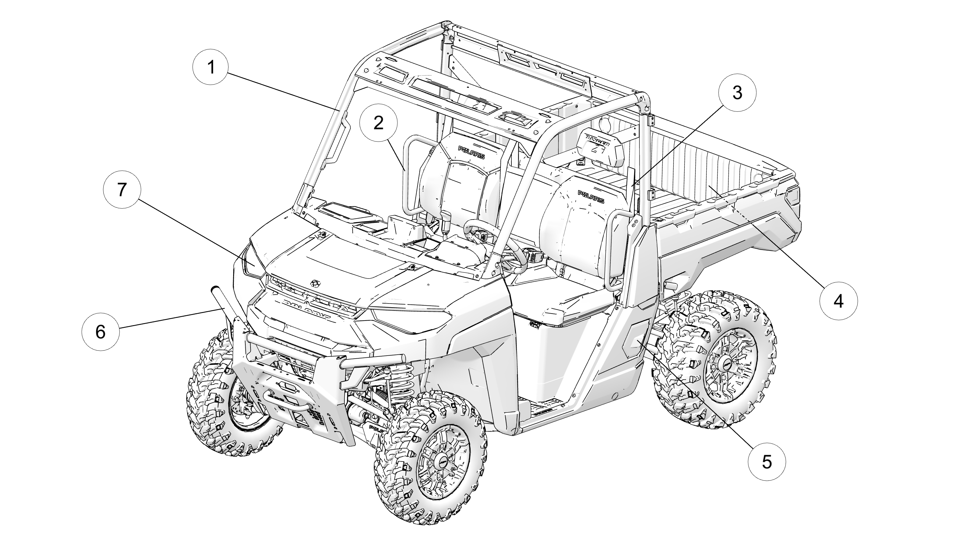
1 ROPS Frame
2 Hip Bar
3 Seat Belt
4 Cargo Box
5 Charge Compartment Door
6 Headlight
7 Front Bumper/Brush Guard
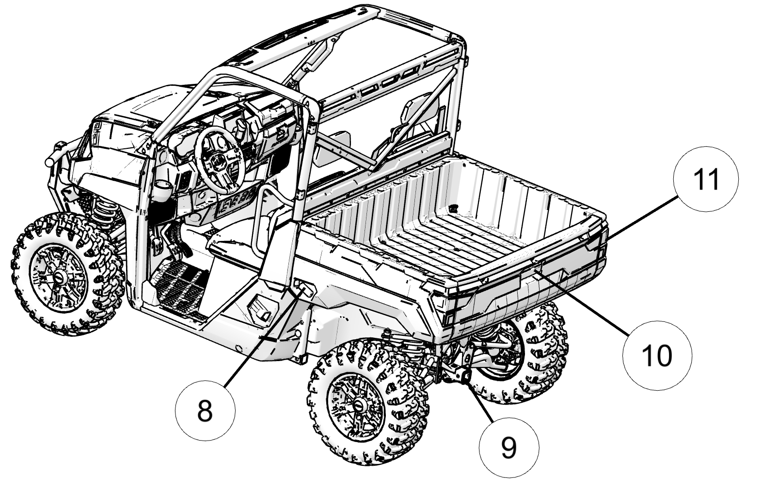
8 Cargo Box Release Lever
9 Receiver Hitch
10 Tailgate Latch
11 Taillight
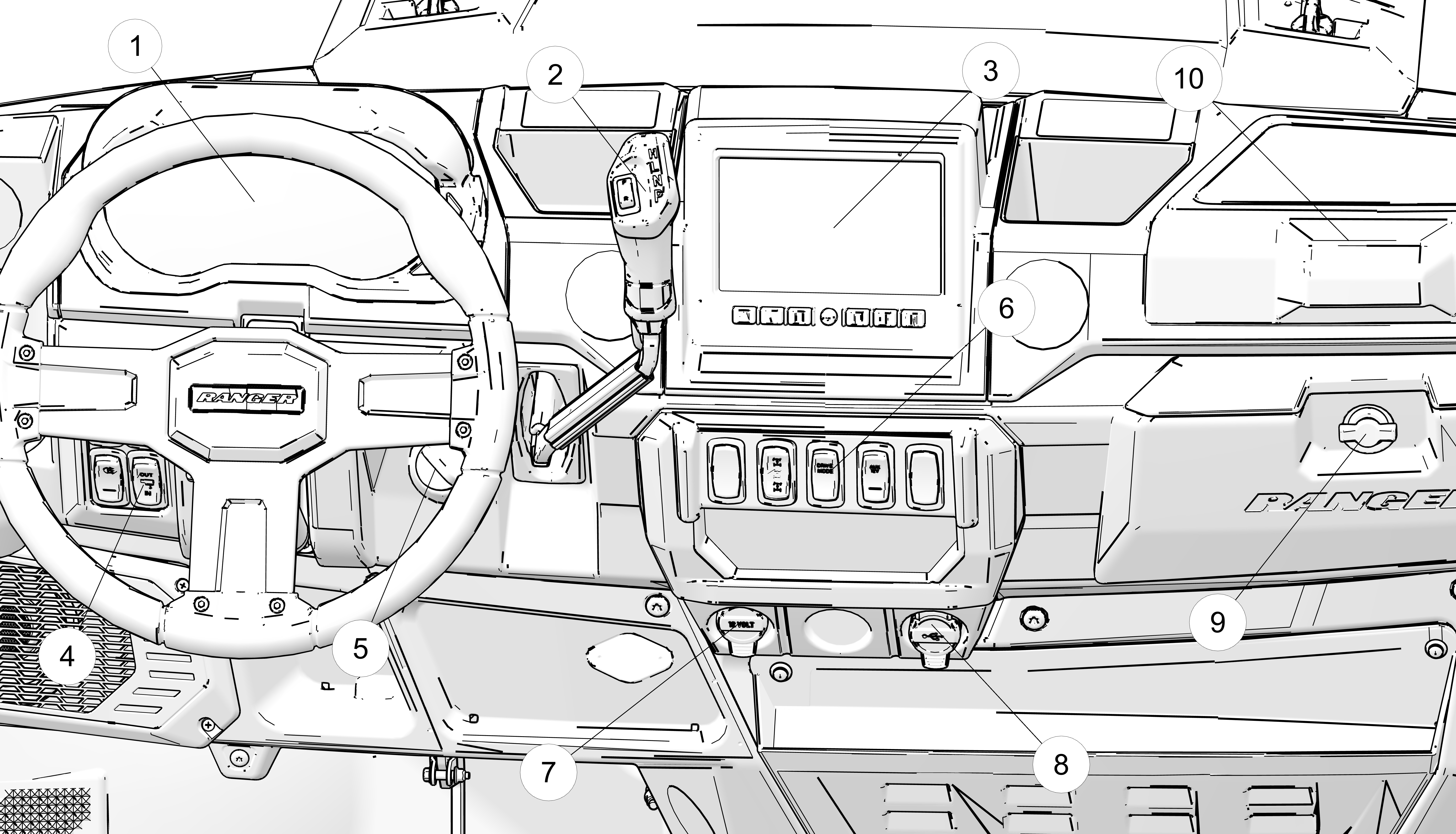
1 Instrument Cluster
2 F/R Switch and Gear Selector
3 Ride Command Display (if equipped)
4 Left-side Switch Cluster
5 Key Switch
6 Right-side Switch Cluster
7 12V Accessory Outlet
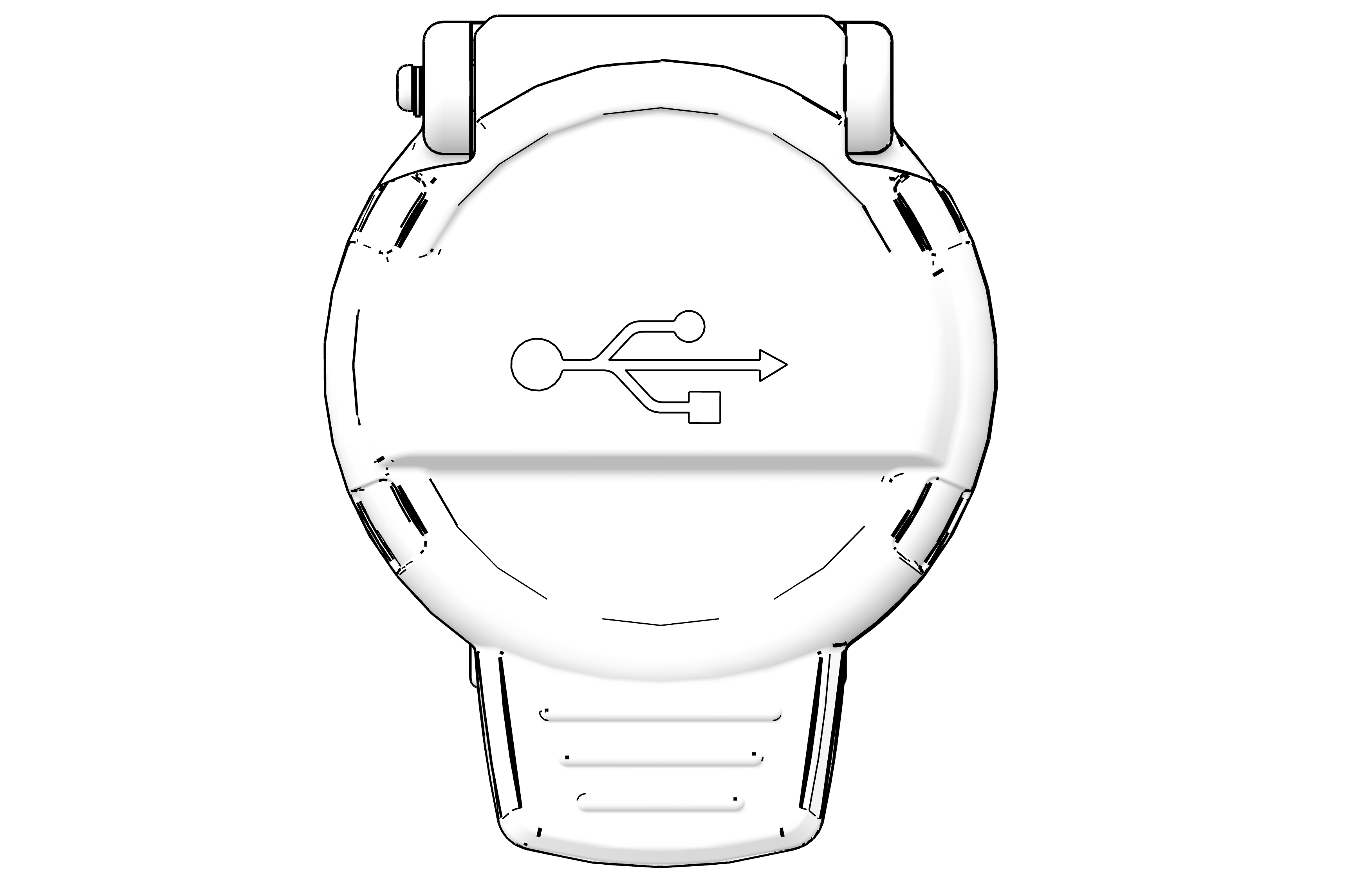
8 USB Outlet
9 Lower Storage Compartment
10 Upper Storage Compartment
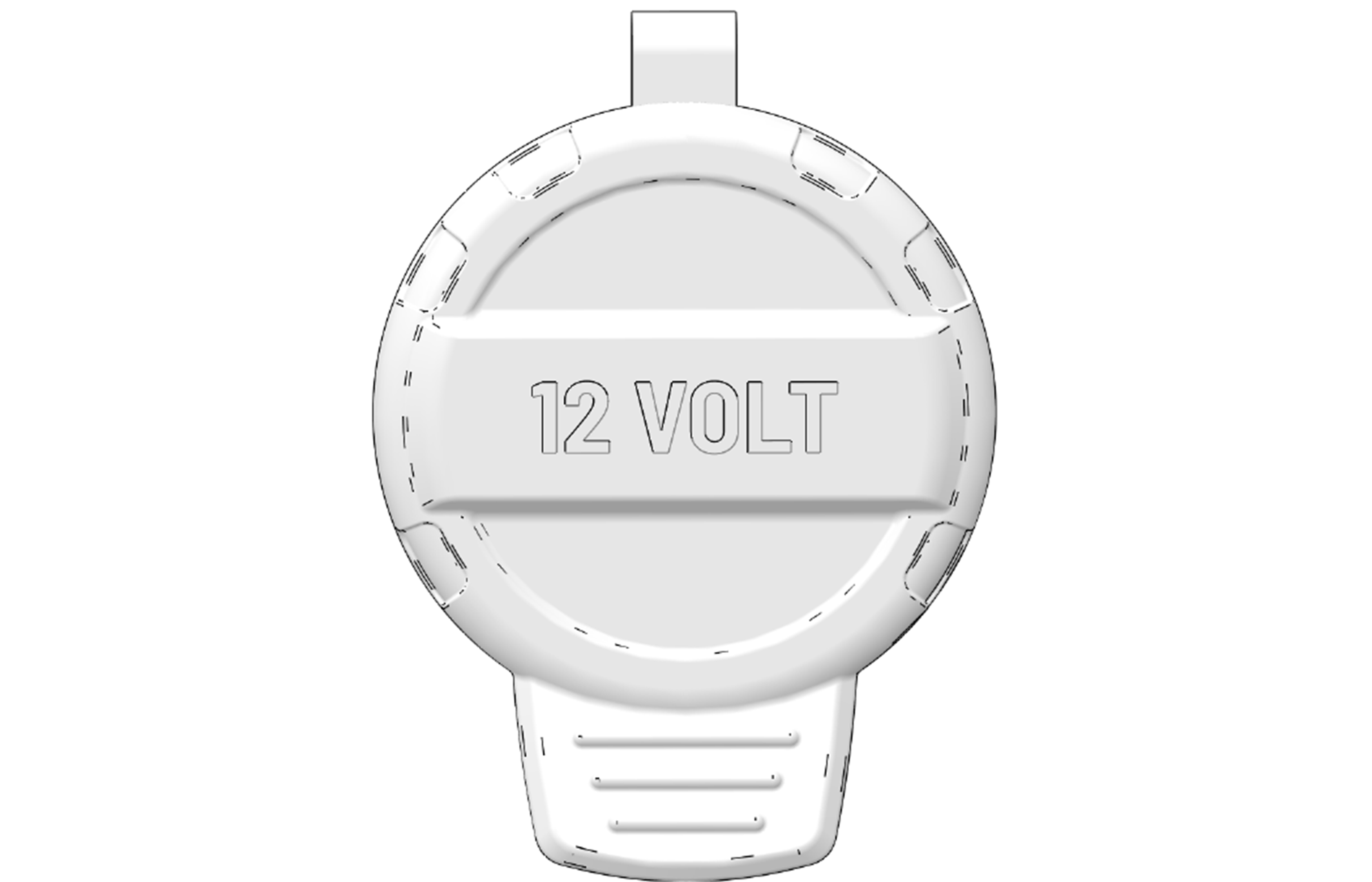
The vehicle is equipped with a 12V–10A accessory outlet on the dash. Use the outlet to power an auxiliary light or other optional accessories or lights. For service, the dash outlet connection is under the dash.
The vehicle is equipped with a USB outlet on the dash. The outlet consists of two USB terminals. For service, the dash outlet connection is under the dash.
Turn the key to the ON position to activate the electrical circuits. Turn the key to the OFF position to disable all electrical circuits. The key can be removed from the switch when it is in the OFF position.
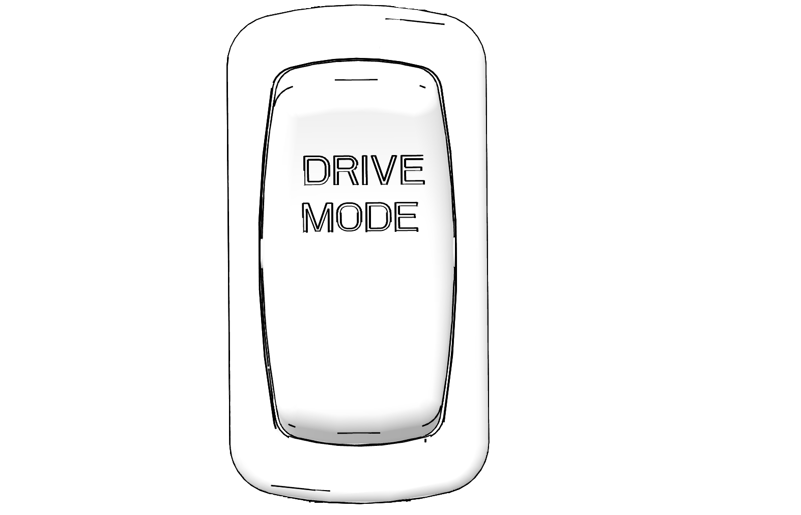
The Drive Mode Switch allows for toggling between three different performance settings - Eco+ Mode, Standard Mode, and Sport Mode. The selected mode can be viewed on the instrument cluster when the vehicle is powered on.
ECO+ Mode
Optimizes torque and top speed
for maximum range and quiet operation while performing light duty
jobs in moderate terrain.
Standard Mode
Optimizes throttle response
for full performance and precision needed for toughest jobs and rough
terrain.
Sport Mode
Optimizes throttle response
for spirited driving and sporty pedal feel for recreational/trail
riding.
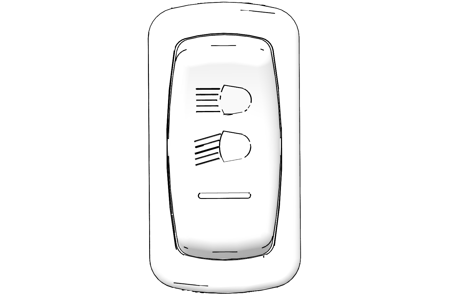
The ignition switch key must be in the ON position to operate the headlights.
Press the top of the rocker switch to place the headlights on HIGH BEAM.
Move the rocker switch to the center position to place the headlights on LOW BEAM.
Press the bottom of the rocker switch to turn OFF the headlights.
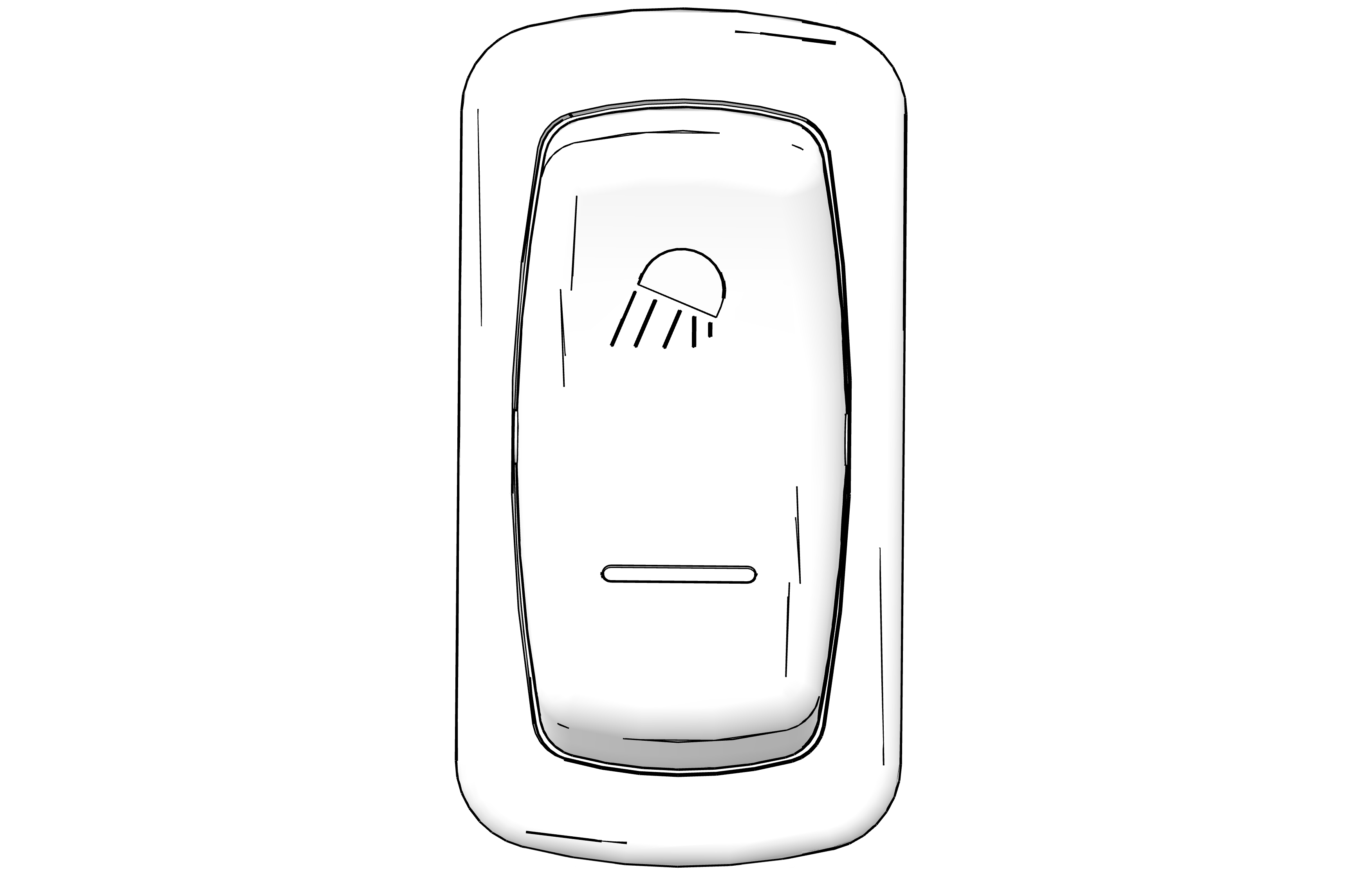
Press the top of the switch to turn the front accent light bar on. Press the bottom of the switch to turn the accent light bar off. The accent light bar can also visually display charge status when the switch is in the ON position while the vehicle is charging. See Vehicle Charge Status for details.
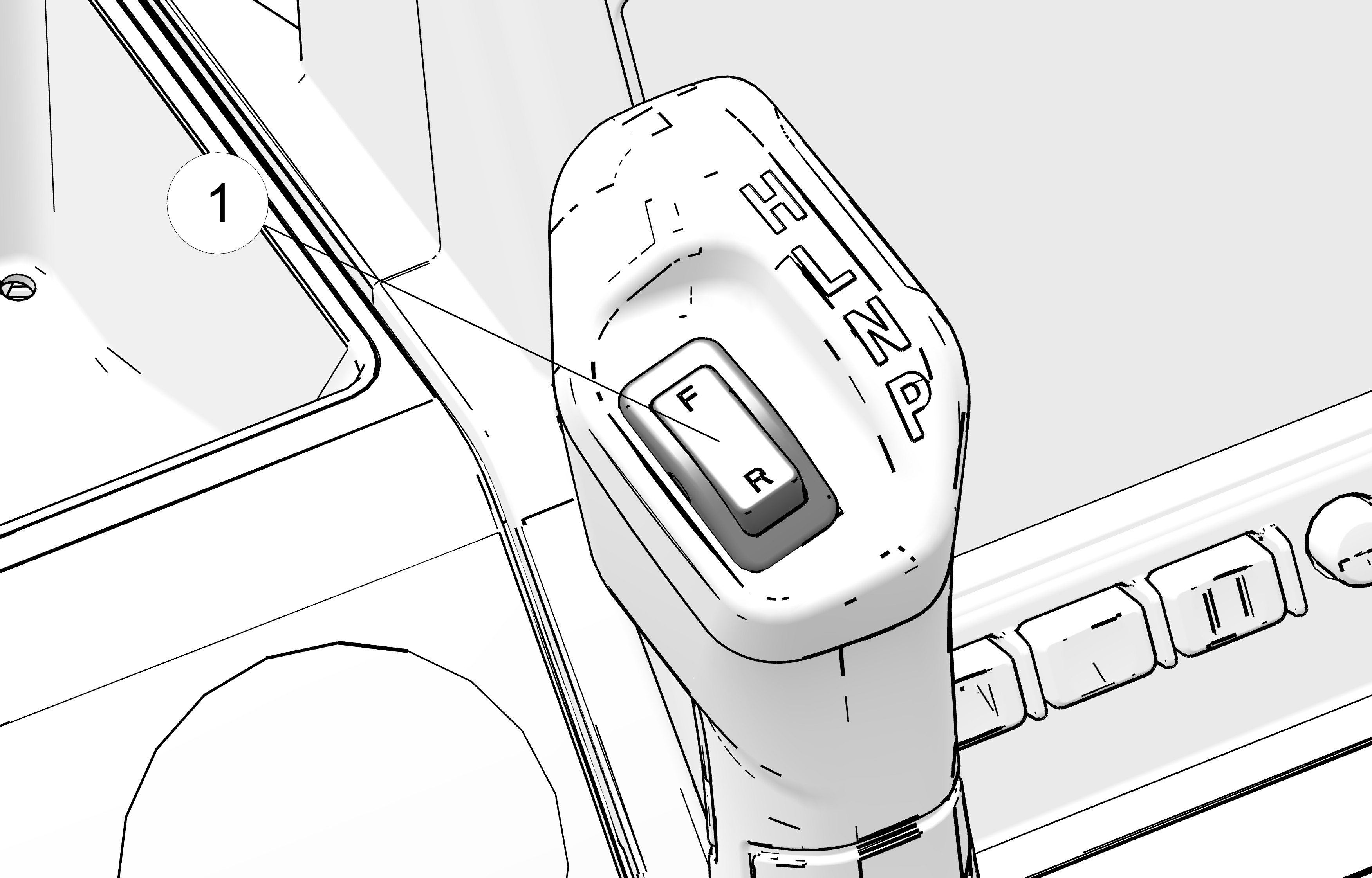
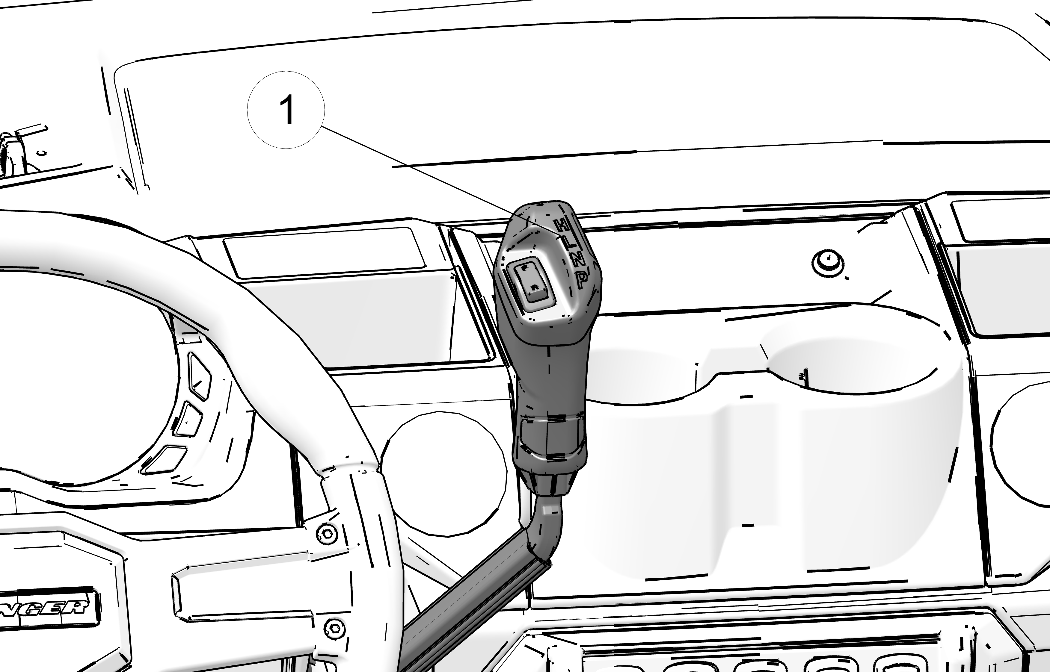
The direction selector switch 1 is located on the gear selector. Pressing the accelerator pedal while the vehicle is in HIGH (H) or LOW (L) gear will move the vehicle in the direction indicated by the direction selector switch.
Press FORWARD (F) to drive the vehicle forward.
Press REVERSE (R) to drive the vehicle in reverse.
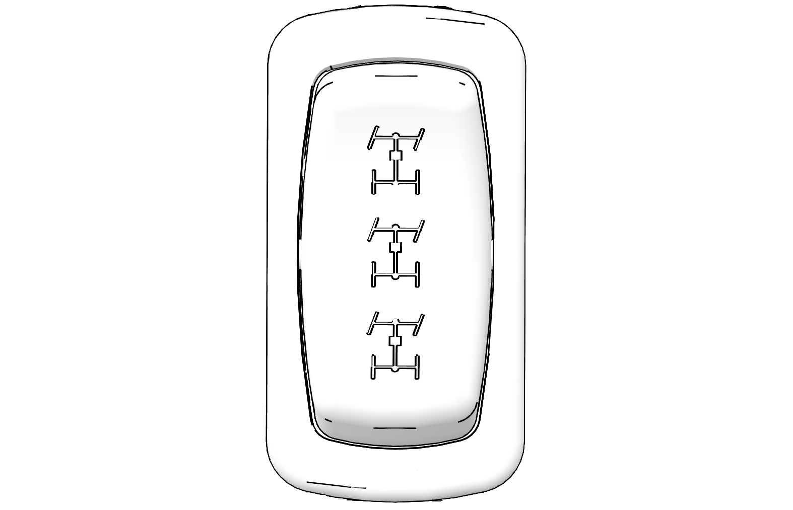
The AWD switch has three positions: All Wheel Drive (AWD), Differential Lock/Two Wheel Drive (2WD) and Off (1WD / Turf Mode).
Press the top of the switch to engage All Wheel Drive (AWD).
Move the switch to the center position to lock the differential and operate in two wheel drive (2WD).
Press the bottom of the switch to unlock the differential and allow the rear drive wheels to operate independently (1WD / Turf Mode). This mode of operation is well suited to turf driving or when active traction is not needed.
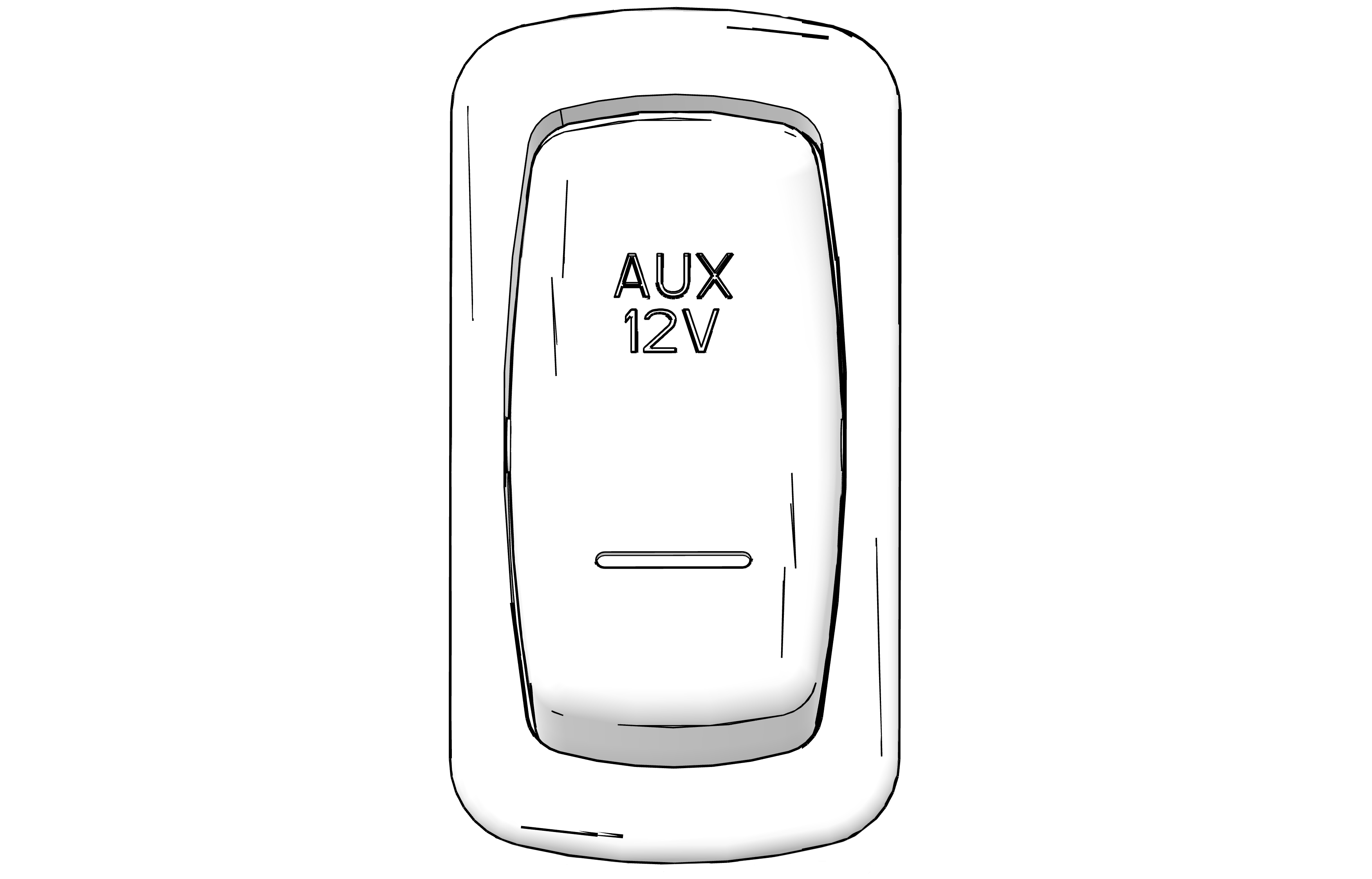
The AUX switch activates power to the rear auxiliary 12V-15A SAE plug. The rear plug is not active/live until the AUX switch is in the ON position.
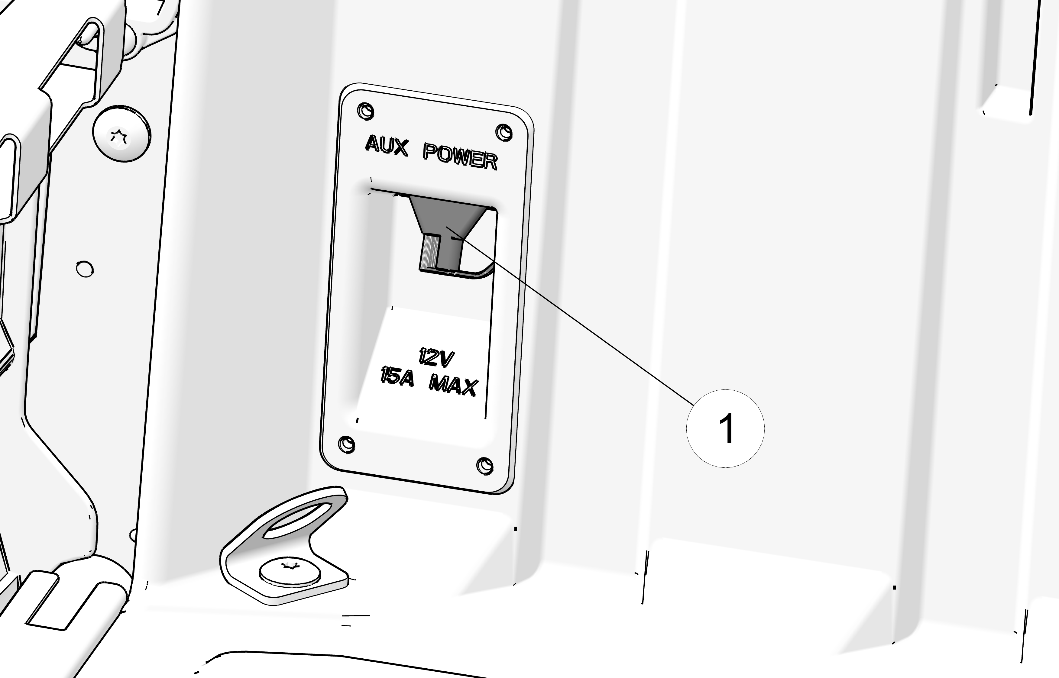
The rear auxiliary 12V-15A SAE port 1 is located on the rear driver-side corner of the cargo box.
To change gears, stop the vehicle and move the lever 1 to the desired gear. Do not attempt to shift gears while the vehicle is moving.
H: High Gear
L: Low Gear
N: Neutral
P: Park
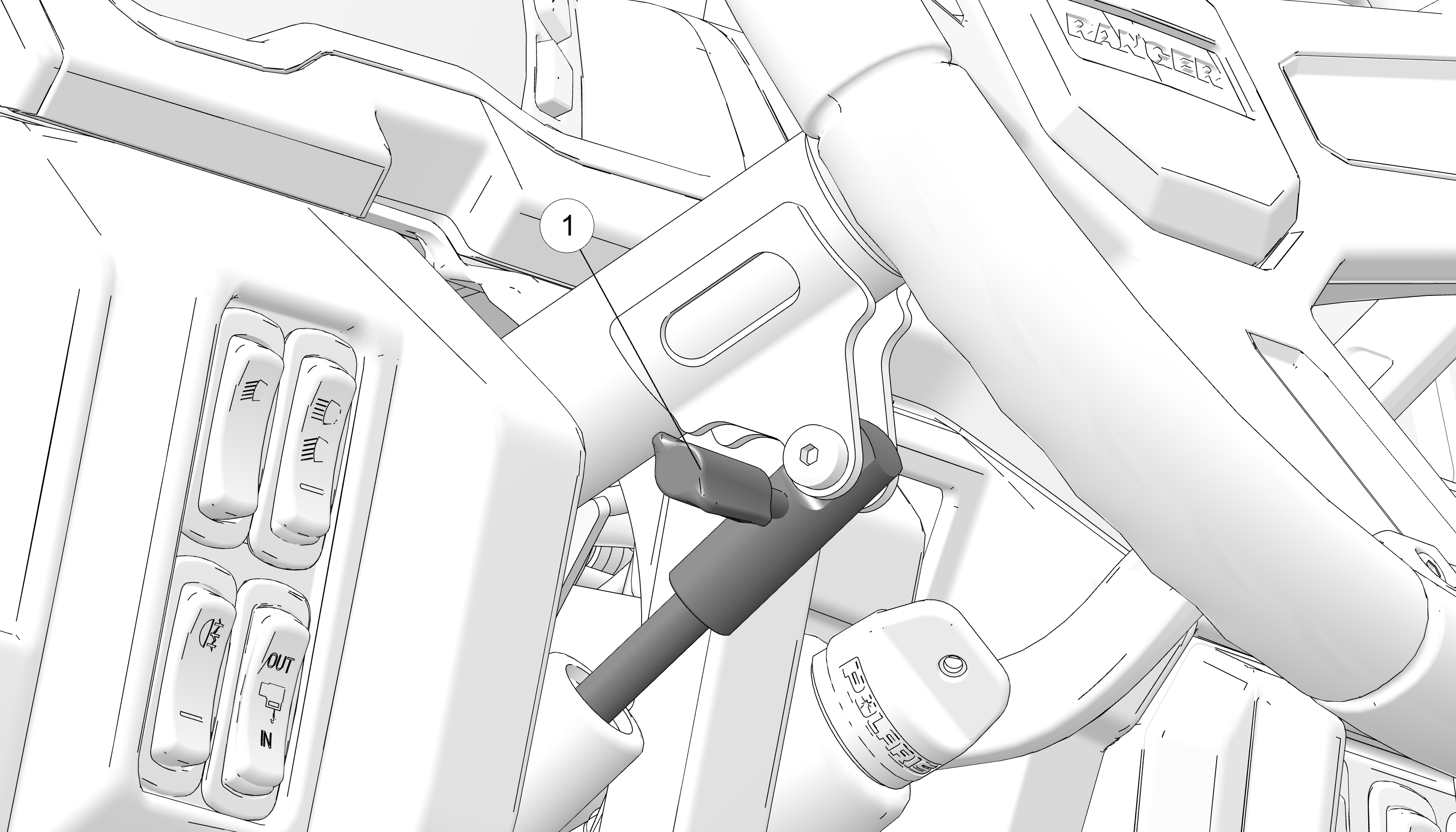
The steering wheel can be tilted upward or downward for rider preference.
Lift and hold the steering wheel adjustment lever while moving the steering wheel upward or downward. Release the lever when the steering wheel is at the desired position.
Always make sure the steering wheel position does not impede proper operation of the brake pedal, accelerator pedal, and all other controls.
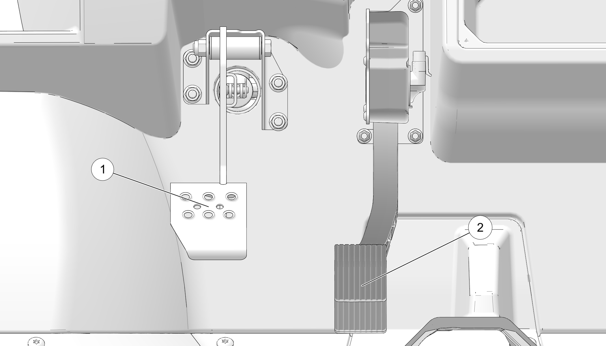
Depress the brake pedal 1 to slow or stop the vehicle. Regenerative braking will be active whenever the brake pedal is used while vehicle is in motion. See Regenerative Braking for details.
When the brake pedal is depressed, the brake light comes on. Check the brake light before each ride.
Turn the key switch to the ON position.
Apply the brakes. The rear brake lights should come on after about 10 mm (0.4 in.) of pedal travel.
Push the accelerator pedal 2 down to accelerate the vehicle. Spring pressure returns the pedal to the rest position when released. Always check that the accelerator pedal returns normally before starting the motor.
This vehicle is equipped with three-point lap and diagonal seat belts for the operator and any passengers. Always make sure the seat belts are secured for all riders before operating. The driver’s seat belt is equipped with a seat belt interlock. Vehicle speed will be limited to 15 MPH (24 km/h) if the seat belt is not secured.
To wear the seat belt properly, follow this procedure:
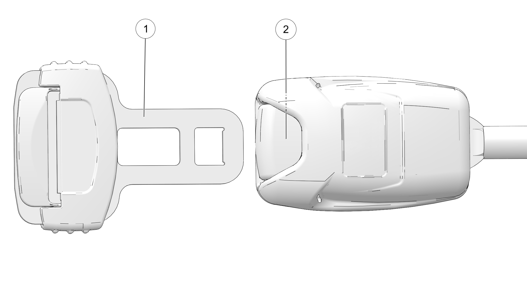
For 3-point belts, pull the seat belt latch 1 downward and across your chest toward the buckle at the inner edge of the seat. The belt should fit snugly across your hips and diagonally across your chest. Make sure the belt is not twisted.
Push the latch plate 1 into the buckle 2 until it clicks.
Release the strap, it will self tighten.
To release the seat belt, press the square red button in the buckle’s center.
Inspect all seat belts for proper operation before each use of the vehicle.
Push the latch plate into the buckle until it clicks. The latch plate must slide smoothly into the buckle. A click indicates that it's securely latched.
Push the red release latch in the middle of the buckle to make sure it releases freely.
Pull each seat belt completely out and inspect the full length for any damage, including cuts, wear, fraying or stiffness. If any damage is found, or if the seat belt does not operate properly, have the seat belt system checked and/or replaced by an authorized dealer.
To clean dirt or debris from the seat belts, sponge the straps with mild soap and water. Do not use bleach, dye or household detergents. Rinse the entire length of the belt webbing. Use a garden hose to flush out the retractor and latch housings regularly.
The electrical compartment is located under the center rear-most seat. Never use this area for storage. Storage compartments are located under all other seats. Remove the storage bin under the center rear-most seat to access the battery and electrical compartment.
Always make sure all seats are properly installed before operating.
To access the storage area under the driver’s seat, reach behind the driver’s seat and pull up on the latch. Roll the bottom of the seat forward toward steering wheel.
To access the storage area under the passenger seat, lift up on the front of the passenger seat and raise it to the upright position.
The Rollover Protective Structure (ROPS) on this vehicle meets OSHA® 1928.53 rollover performance requirements. Always have your authorized dealer thoroughly inspect the ROPS if it ever becomes damaged in any way.
No device can assure occupant protection in the event of a rollover. Always follow all safe operating practices outlined in this manual to avoid vehicle rollover.
This vehicle is equipped with a receiver hitch bracket for a trailer hitch. Trailer towing equipment is not supplied with this vehicle.
To avoid injury and property damage, always heed the warnings and towing capacities.
Always inspect cab nets and latches for tightness, wear and damage before each use of the vehicle. Use the strap adjusters to tighten any loose straps. Promptly replace worn or damaged cab nets and latches with new cab nets and latches. Your Polaris dealer or qualified technician can assist.
Position the lower net rod into the mount at floor level.
Connect the latch at the top edge of the net to the receiver latch mounted on the front frame.
To exit the vehicle, release the top front latch.
Rotate the net rearward and slide the lower net rod out of the mount to remove it.
Allow the net to hang freely outside the vehicle while dismounting.
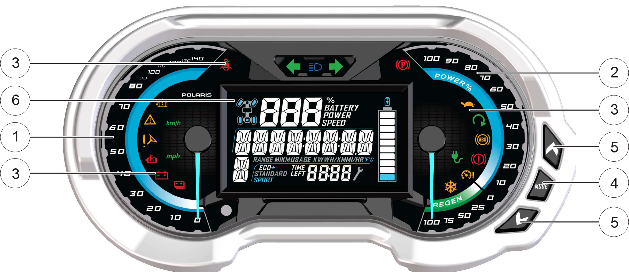
1 Speedometer
2 Accelerator/Brake Regen Power Level (%)
3 Indicator Lamps
4 MODE Button
5 Toggle Buttons
6 Rider Info Center
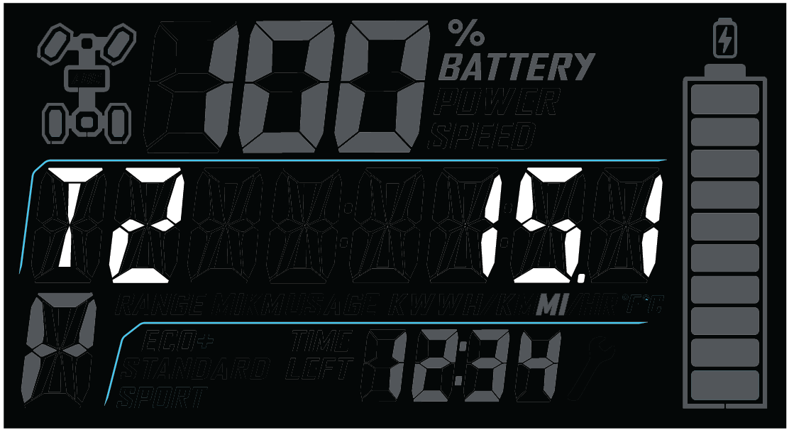
The speedometer displays vehicle speed in either miles per hour (MPH) or kilometers per hour (km/h).
The POWER% level displays the percentage (%) of motor power applied as a result of pushing down on the accelerator pedal.
The REGEN level displays the percentage (%) of available regenerative braking torque applied. See Regenerative Braking for details.
Press and hold the MODE button to enter or exit the settings menu. Press and release the MODE button to cycle through Area 1 modes and to select an item. See Mode Information Displays for details.
Press and release either toggle button to cycle through the options menu or Area 2 modes. Press and hold either toggle button to reset an item.
| Indicator | Icon | Function |
|---|---|---|
| Vehicle Speed |

|
When standard mode is selected, speed displays in miles per hour. |

|
When metric mode is selected, speed displays in kilometers per hour. | |
| High-Voltage Battery Pack |

|
This indicator illuminates when a failure or fault has occurred in the vehicle’s high-voltage battery pack. |
| Check 12V Battery |

|
This indicator illuminates when the 12V battery is exhibiting low voltage. |
| Over Temperature |
|
This indicator illuminates when components of the electronic powertrain (such as the motor or high-voltage battery) are overheating. Continued operation may result in reduced performance to allow powertrain component temperatures to recover. |
| EPS Warning (if equipped) |

|
This indicator illuminates briefly when the key is turned to the ON position. If the light remains on, the EPS system is inoperative. See your dealer or other qualified person as soon as possible for repair. Continued operation could result in permanent damage to the EPS unit and increased steering effort. |
| Amber Warning Light (AWL) |

|
This indicator illuminates when an error condition or minor
fault has been detected by the vehicle’s computer. Consult Diagnostic Trouble Codes and Diagnostic Trouble Codes to identify the condition/fault detected. See your dealer or other qualified person if the condition/fault persists. |
| Malfunction Indicator Light (MIL) |

|
This indicator illuminates when an error condition or serious
fault has been detected by the vehicle’s computer. Consult Diagnostic Trouble Codes and Diagnostic Trouble Codes to identify the condition/fault detected. See your dealer or other qualified person if the condition/fault persists. |
| Helmet/Seat Belt |
|
This indicator illuminates as a reminder to the operator to ensure all riders are wearing helmets and seat belts before operating. The driver’s seat belt is equipped with a seat belt interlock. Vehicle speed will be limited to 15 MPH (24 km/h) if the seat belt is not secured. |
| High Beam |

|
This indicator illuminates when the headlamp switch is set to high beam. |
| Park Brake (if equipped) |

|
This indicator illuminates when the Park Brake is applied (if equipped). |
| Speed Limitation Indicator |

|
This indicator illuminates when the Speed Limitation function is active. |
| Active Status Indicator |

|
This indicator illuminates when the vehicle accelerator pedal is active. Pressing on the accelerator pedal when this light appears will result in movement in the direction selected (forward or reverse). |
| Charging Indicator |

|
This indicator illuminates to confirm the vehicle is connected to a charger. It does not confirm the flow of charge to the vehicle, which is only confirmed by text on the Rider Information Center or the Ride Command display (if equipped). If this light flashes, an error has occurred and the vehicle will not charge. |
| Brake Failure Indicator (International Models Only) |

|
This indicator illuminates when a brake fault or failure has occurred. |
| Overspeed Indicator |

|
This indicator illuminates when the vehicle’s Speed Limitation function is active and the vehicle travels at speeds in excess of the set limitation (such as when moving downward on a hill). |
| Cold Temperature Indicator |

|
This indicator illuminates when vehicle components are below their ideal operating temperature; 32° F (0° C). The vehicle may experience reduced performance when this light is active. Allow the battery heaters several minutes to warm up before operating. See Charging in Extreme Ambient Temperatures for details on extreme weather operation. |
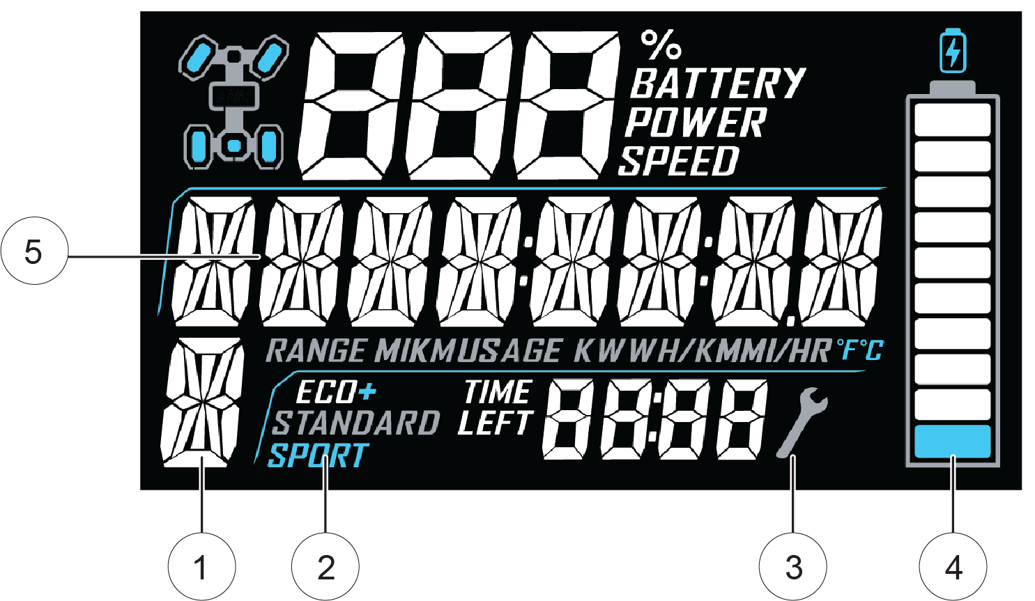
| 1 | Gear Indicator | This indicator displays gear shifter position. H = High Gear L = Low Gear N = Neutral R= Reverse P = Park -- = Gear Signal Error (or shifter between gears) |
| 2 | Drive Mode Indicator | This indicator shows whether ECO+, STANDARD, or SPORT Mode is active. See Drive Mode Switch for details. |
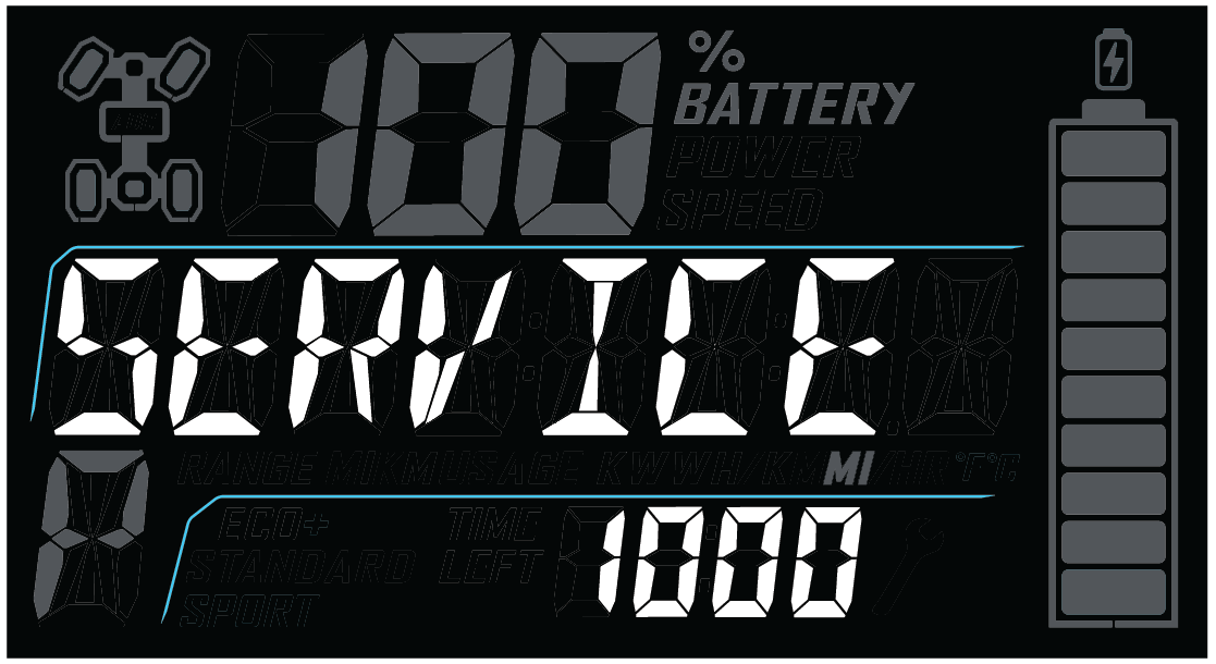
| 3 | Service Indicator | A flashing wrench symbol alerts the operator that the preset service interval has been reached. Your Polaris dealer, or other qualified person, can provide scheduled maintenance. See Programmable Service Interval for resetting instructions. |
| 4 | Remaining Charge Gauge | The segments of the charge gauge show the level of charge held by the high-voltage battery pack(s). When the last segment clears, a low charge warning is activated. The outline of the charge display will flash. Recharge the vehicle. |
| 5 | Speed Limitation (if equipped) | This vehicle may be equipped with a maximum speed limitation function. This would be displayed on the screen as “LIM” followed by the speed. “LIM 30” for example. |
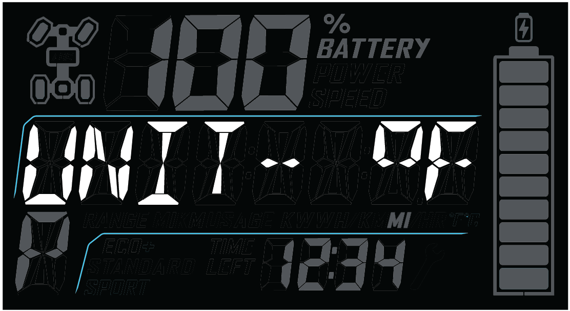
The rider information center is located in the instrument cluster. All segments will light up for one second at start-up.
The information center is set to display standard units of measurement and a 12-hour clock at the factory. To change to metric and/or a 24-hour clock hold the mode button and cycle to the clock menu. Use the directional arrows to change the clock settings.
If the instrument cluster fails to illuminate, a battery over-voltage may have occurred and the instrument cluster may have shut off to protect the electronic speedometer. If this occurs, your Polaris dealer, or other qualified person, can provide proper diagnosis.
The rider information center contains three areas that display mode information.
| 1 Area 1 Modes | Description |
| Battery Pack State of Charge (SoC) | Remaining battery pack charge (%) |
| Vehicle Speed | Speed of vehicle (MPH/KPH) |
| Motor Power Level | Motor power applied as a result of pushing down on the accelerator pedal (%) |
| 2 Area 2 Modes | Description |
| Odometer | The odometer records and displays the distance traveled by the vehicle. |
| Trip Meters (T1/T2) | A trip meter records the distance traveled by the vehicle if reset before each trip. To reset, see Trip Meter. |
| Ambient Temperature | Displays the ambient temperature sensed by the vehicle. See Display Units (Standard/Metric) to set desired units. |
| Efficiency (Watt-hours per mile/km) |
Displays average battery pack output per mile/km traveled. |
| Range | Estimated remaining range (miles/km). See Estimated Remaining Range for details on how estimated remaining range is calculated. |
| Service Interval | A flashing wrench symbol indicates that the preset service interval has been reached. To reset, see Programmable Service Interval. |
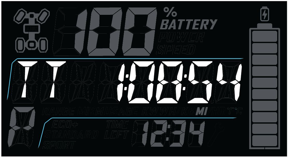
| 3 Area 3 Modes | Description |
| Clock | The clock displays time in a 12-hour or 24-hour format. To reset, see Clock. |
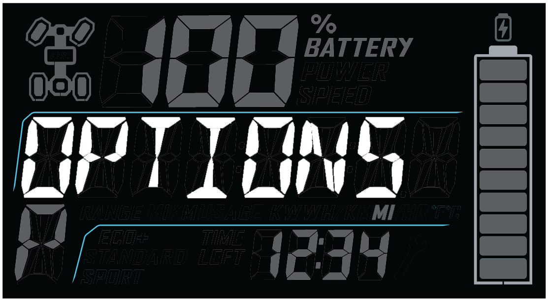
Press and release the MODE button to cycle through the Area 1 modes until the desired default mode displays. See the Mode Information Displays section for details.
Press and hold the MODE button to enter the settings menu.
The OPTIONS screen will display for a few seconds.
Press and release either toggle button to cycle to the desired option.
Press MODE to select the option.
Press either toggle button to cycle to the desired setting.
Press MODE to save and exit to the settings menu.
Press and hold the MODE button to exit the settings menu.
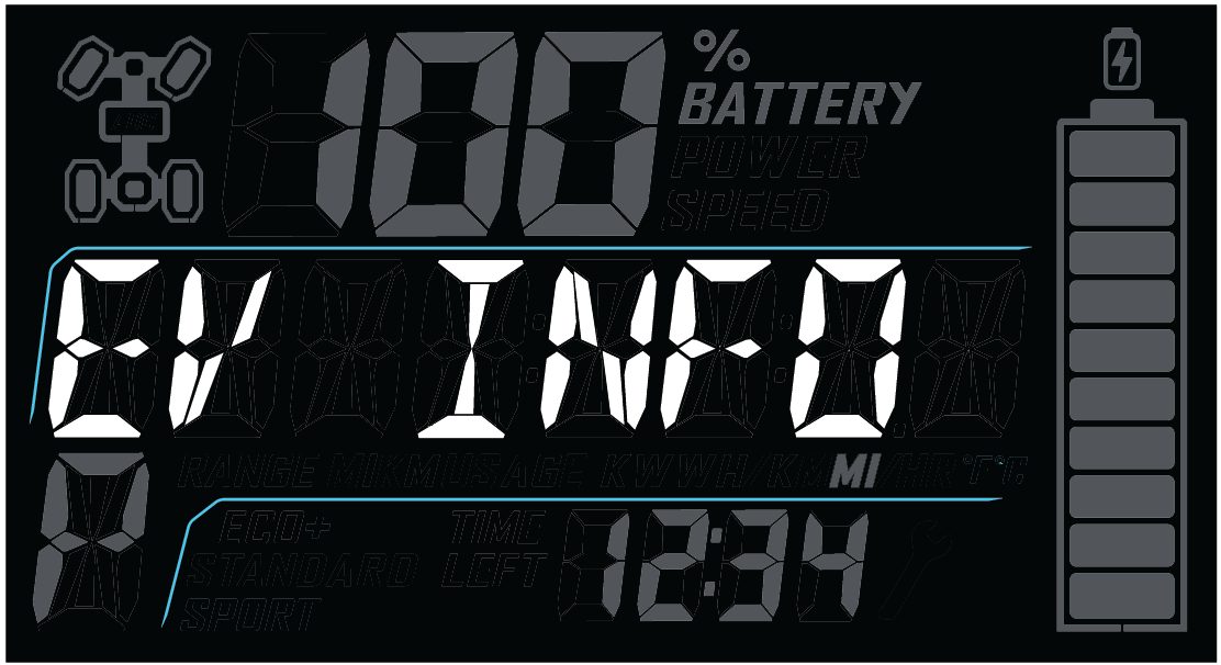
Electric vehicle (EV) component details can be viewed using the EV INFO option.
Press and hold the MODE button to enter the settings menu.
Press either toggle button to cycle to the “EV INFO” option. Press MODE to select.
Press either toggle button to cycle to the desired electric component status.
Motor Temperature
Motor Control Unit (MCU) Temperature
Vehicle Dynamics Control (VDC)
Battery Pack Life Efficiency (Wh per mile/km)
Battery Pack Temperature
Press MODE to return to the settings menu.
The information center backlight can be set to either blue or red.
Press and hold the MODE button to enter the settings menu.
Press either toggle button to cycle to the “BL COLOR” option. Press MODE to select.
Press either toggle button to cycle to the desired setting.
Press MODE to save and exit to the settings menu,
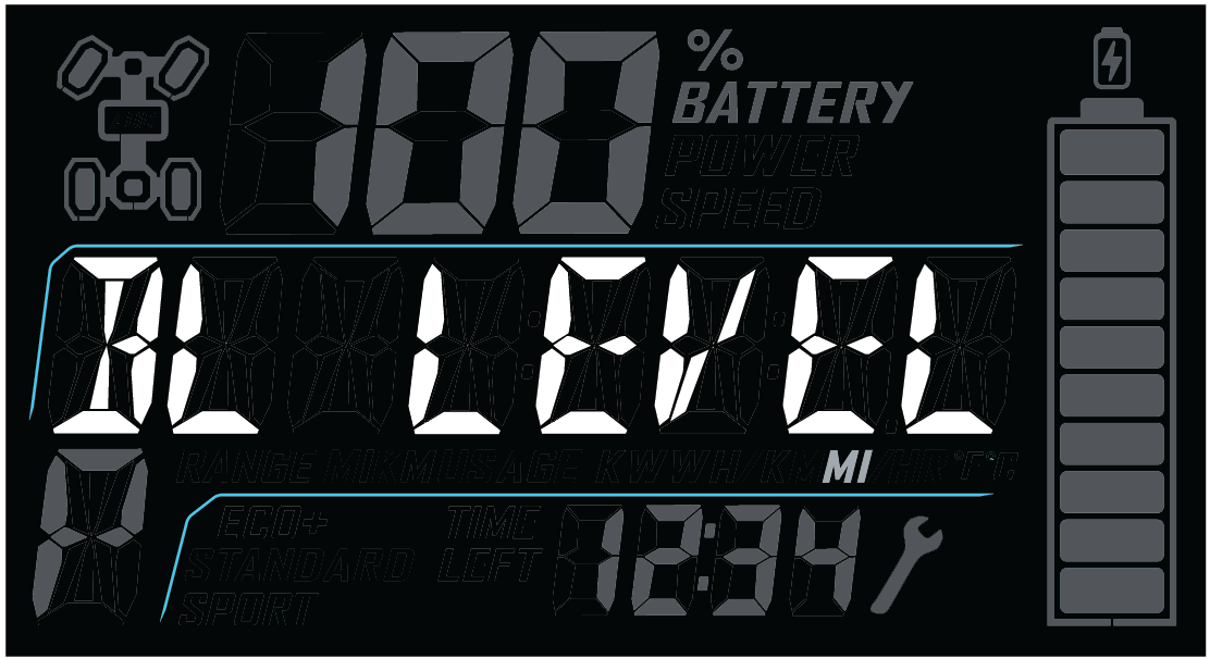
The information center backlight can be adjusted to desired brightness.
Press and hold the MODE button to enter the settings menu.
Press either toggle button to cycle to the “BL LEVEL” option. Press MODE to select.
Press “UP” button to increase brightness. Press “DOWN” button to decrease brightness.
Press MODE to select and exit to the settings menu.
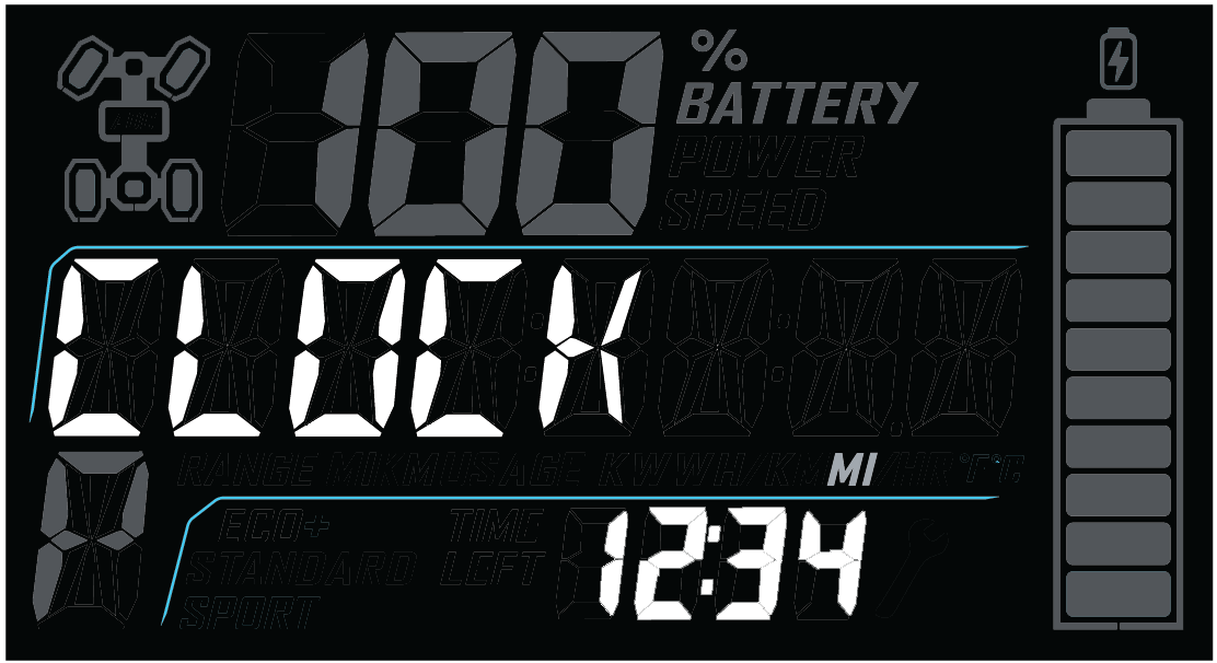
The clock must be reset any time the battery has been disconnected or discharged.
Press and hold the MODE button to enter the settings menu.
Press either toggle button to cycle to the “CLOCK” option. Press MODE to select.
Press either toggle button to cycle to the desired setting (12H or 24H). Press MODE to select.
Press either toggle button to change each segment of the clock. Press MODE to accept a change and advance to the next segment.
Press and hold the Mode button to enter the settings menu.
Use the toggle buttons to find the Speed Limitation screen (SPD LIM). Press the MODE button to select.
Choose your desired maximum speed (between 30-85 km/h) by using the toggle buttons.
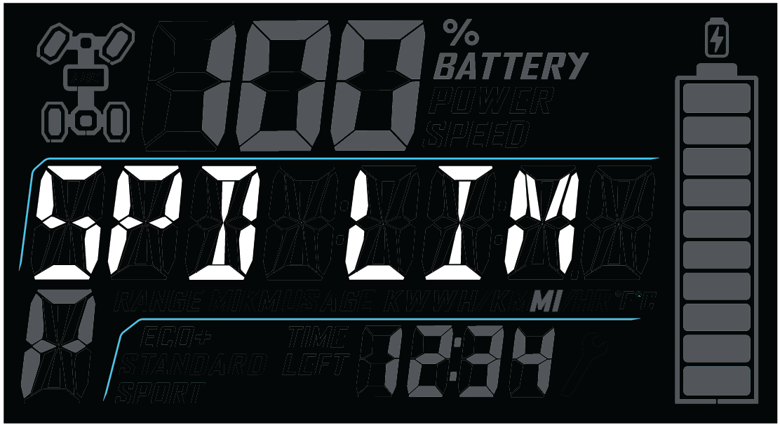
The Speed Limitation feature is disabled automatically when the MODE button is pressed again or ignition switch is in the OFF position.
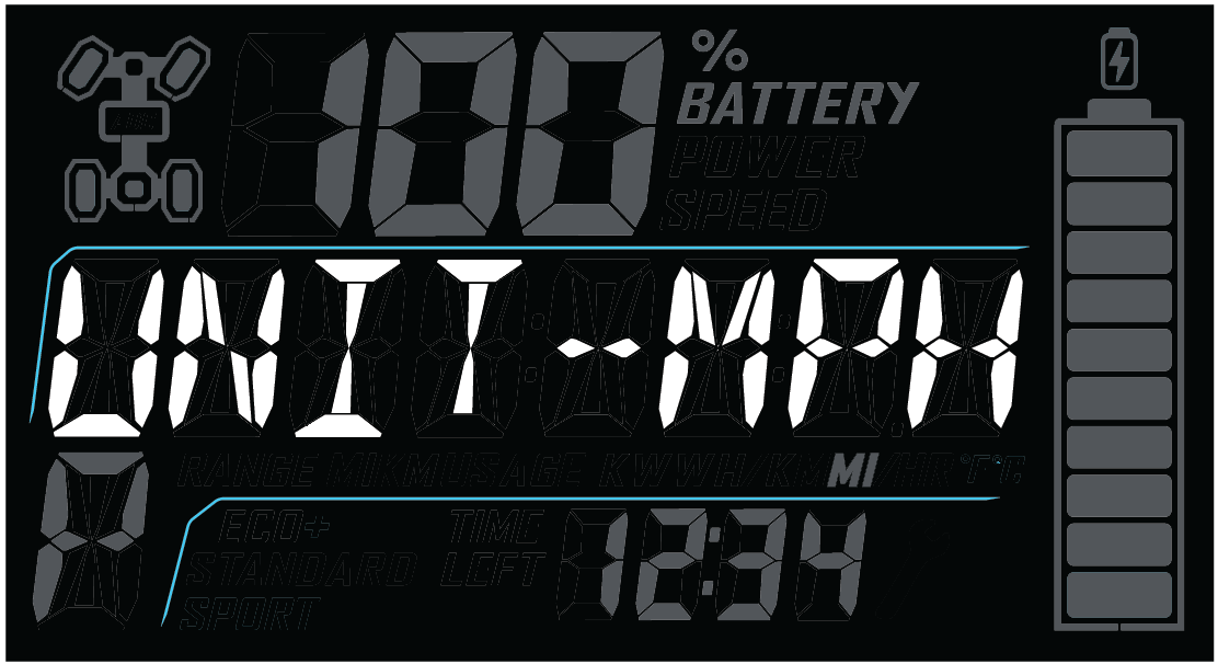
Press and hold the MODE button to enter the settings menu.
Press either toggle button to cycle to the desired “UNITS” option (distance, temperature or volume). Press MODE to select.
Press either toggle button to cycle to the desired setting.
Press MODE to save and exit to the settings menu.
Use a trip meter to track the distance traveled during a specific trip or period of time. Reset the meter to zero before traveling.
Press either toggle button to cycle to the desired trip meter option (T1 or T2).
Press and hold either toggle button until the meter resets to zero.
Use a trip time meter to track the travel time during a specific trip. Reset the meter to zero before traveling.
Press either toggle button to cycle to the trip time option (TT).
Press and hold either toggle button until the meter resets to zero.
The service interval counter is programmed to 25 miles at the factory. As vehicle operation increases, the counter decreases. The wrench icon will flash for about 10 seconds when the counter reaches zero (0), and each time the key is turned on thereafter, until the counter is reset.
When this feature is enabled, it provides a convenient reminder to perform routine maintenance. Refer to the Periodic Maintenance Chart for recommended service intervals.
Use the following procedure to reset or change the service interval.
Press and hold the MODE button to enter the settings menu.
Press either toggle button to cycle to the “SERVICE” option. Press MODE to select.
Press MODE to reset the existing value and exit, or press either toggle button to change the value. Press MODE to save and exit to the settings menu.
The optional PIN Activated Security System (P.A.S.S.) is to prevent unauthorized use. When enabled, the vehicle cannot be operated until a valid passcode has been entered using the Instrument Cluster.
To enable/disable P.A.S.S. using the Instrument Cluster, follow the procedures below.
After activating P.A.S.S. for the first time you must power down the vehicle and allow the electronic control module (ECM) to fully shutdown before restarting. This may take up to three minutes.
Once a new passcode has been enabled, it cannot be changed unless you first disable the system. Then you can re-follow the steps outlined in the ENABLE P.A.S.S. section to enter a new passcode.
Press and hold the MODE button to enter the “OPTIONS” menu.
Use the UP/DOWN toggle buttons to cycle through options until “REQUIRE PIN TO START” appears. Press the MODE button to select.
If required, “ENTER NEW PIN” will appear. Use the UP/DOWN toggle buttons to cycle to your desired first digit. Press the MODE button to select the digit.
Continue until all four digits of your desired passcode have been selected. Once finished, “NEW PIN SET” will flash momentarily and then revert back to the “REQUIRE PIN TO START” screen.
Please record your passcode.
To enable your new passcode, use the UP/DOWN toggle buttons to change the flashing “OFF” at bottom of screen to “ON”. If this step is skipped, P.A.S.S. will not be enabled.
Press the MODE button to re-enter the “OPTIONS” menu. The vehicle will now require passcode entry before next startup.
You can exit the “OPTIONS” menu three different ways.
Toggle to “EXIT” and press the MODE button.
Hold the MODE button for a few seconds.
Do nothing, allowing the system to automatically revert back to the main screen.
Press and hold the MODE button to enter the “OPTIONS” menu.
Use the UP/DOWN toggle buttons to cycle through options until “REQUIRE PIN TO START” appears. Press the MODE button to select.
Enter current passcode.
Use the UP/DOWN toggle buttons to change the flashing “ON” at bottom of screen to “OFF”.
Press the MODE button to re-enter the “OPTIONS” menu. P.A.S.S. is now disabled.
You can exit the “OPTIONS” menu three different ways.
Toggle to “EXIT” and press the MODE button.
Hold the MODE button for a few seconds.
Do nothing, allowing the system to automatically revert back to the main screen.
The error screen displays only when the Advanced Warning Light (AWL) indicator is on or when it goes on and off during one startup cycle. Error codes are not stored. When the key switch is in the OFF position, the code and message is lost but will reappear if the fault reoccurs after restarting the vehicle.
Code definitions can be referenced on Diagnostic Trouble Codes.
If the Malfunction Indicator Light (MIL) or the EPS lamp illuminates, retrieve the active error codes from the display.
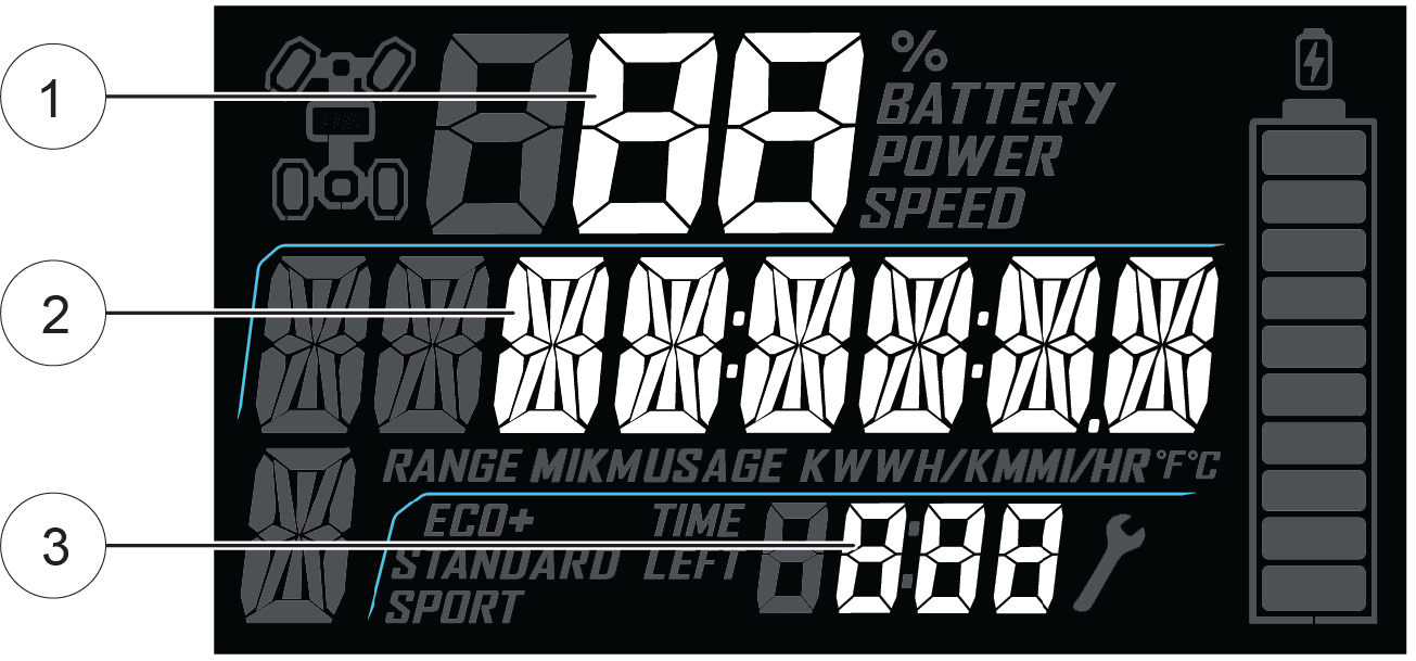
Press and hold the MODE button to enter the settings menu.
Press either toggle button to cycle to the “DIAGCODE” option. Press MODE to select.
More than one diagnostic code may be present. Press the toggle UP button to see if more codes are present. Press MODE to select a code.
Record the three (3) numbers displayed.
Press MODE to exit to the settings menu.
Scan the QR Code® to access the Ride Command User’s Guide. You will find up-to-date instructions for your Ride Command display’s features, including Ride Command+. For more information regarding renewal of your vehicle’s Ride Command+ service, visit offroad.polaris.com.

Before riding with your new display, do the following:
Download the Polaris RIDE COMMAND App from the Apple®/Google Play® store and create your personalized account.
Check your display to ensure you have the appropriate maps and trails visible for your area. To change or update maps/trails see Update Maps.
Trails change often, and the trail data file is only considered valid for 90 days after the release date. Please keep your trail data up to date. Download the latest trails at http://ridecommand.polaris.com.
Phone functionality is dependent on the capabilities of your cell phone.
This equipment has been tested and found to comply with the limits for a Class B digital device, pursuant to part 15 of the FCC Rules. These limits are designed to provide reasonable protection against harmful interference in a residential installation. This equipment generates, uses and can radiate radio frequency energy and, if not installed and used in accordance with the instructions, may cause harmful interference to radio communications. However, there is no guarantee that interference will not occur in a particular installation. If this equipment does cause harmful interference to radio or television reception, which can be determined by turning the equipment off and on, the user is encouraged to try to correct the interference by one or more of the following measures:
Reorient or relocate the receiving antenna.
Increase the separation between the equipment and receiver.
Connect the equipment into an outlet on a circuit different from that to which the receiver is connected.
Consult the dealer or an experienced radio/TV technician for help.
This vehicle contains the following radio equipment or components that contain radio equipment:
|
COMPONENT |
COMPONENT ID |
MANUFACTURER |
|---|---|---|
|
9200 Series Display |
2AOW7-P001 |
Polaris Inc. |
|
Polaris Plug-in Dongle |
2AHPN-HSA-20NP-PB |
Harman International Industries |
This device complies with part 15 of the FCC Rules. Operation is subject to the following two conditions: (1) This device may not cause harmful interference, and (2) this device must accept any interference received, including interference that may cause undesired operation.
Changes or modifications not expressly approved by the party responsible for compliance could void the user’s authority to operate the equipment.
This vehicle contains the following radio equipment or components that contain radio equipment:
|
COMPONENT |
COMPONENT ID |
MANUFACTURER |
|---|---|---|
|
9200 Series Display |
5966A-P001 |
Polaris Inc. |
|
Polaris Plug-in Dongle |
6434C-HSA20NPPB |
Harman International Industries |
This device contains license-exempt transmitter(s)/receiver(s) that comply with Innovation, Science and Economic Development Canada’s license-exempt RSS(s). Operation is subject to the following two conditions:
This device may not cause interference.
This device must accept any interference, including interference that may cause undesired operation of the device.
Pour satisfaire aux exigences en matière d’exposition aux champs RF, cet appareil et ses antennes doivent fonctionner à une distance d’au moins 20 cm de toute personne.
Cet appareil contient des émetteurs/récepteurs exempts de licence qui sont conformes aux CNR exempts de licence d’Innovation, Sciences et Développement économique Canada. Le fonctionnement est sujet aux deux conditions suivantes:
L’appareil ne doit pas produire de brouillage.
L’appareil doit accepter tout brouillage radioélectrique subi, même si le brouillage est susceptible d’en compromettre le fonctionnement.
This vehicle contains the following radio equipment or components that contain radio equipment:
| Component | 9200 Series Display |
| Component ID | RC-7 |
| Manufacturer | Polaris Inc. |
| *Transmitting Frequency | 2402 - 2480 MHz |
| Max RF Transmitting PWR | 0.2432 W |
| *Other transmitting radio frequencies may exist outside of EU markets. | |
Hereby, Polaris Industries Inc. declares that the above radio equipment is in compliance with Directive 2014/53/EU.
The full text of the EU declaration of conformity is available at the following internet address:
https://www.polaris.com/en-us/radio-conformity/
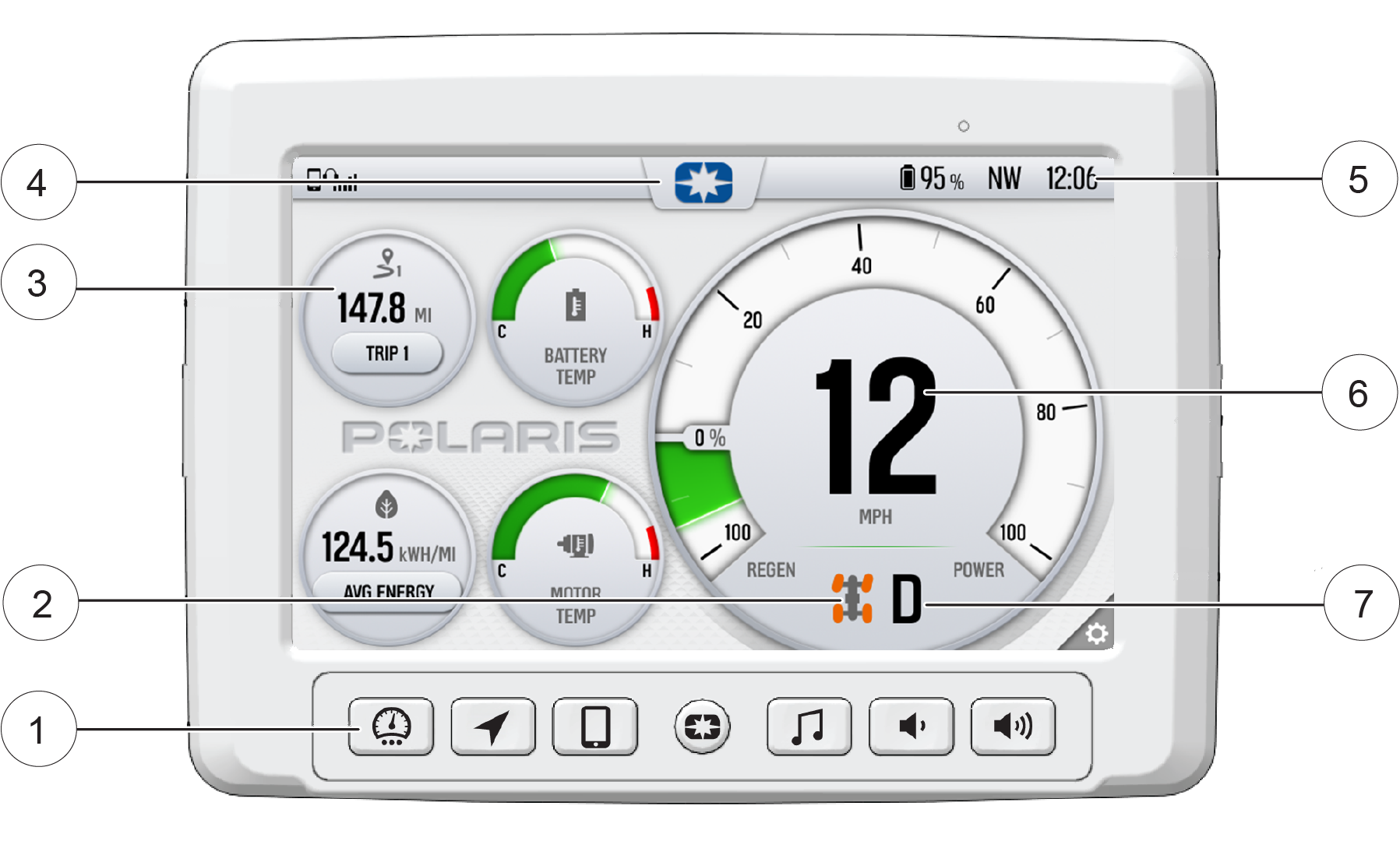
1 Ride Command Buttons
2 Driveline Mode
3 Widgets
4 Settings
5 Icon Bar
6 Speedometer/Tachometer
7 Gear Status
| Button | Description | Function |
|---|---|---|

|
Menu Button | Press the Menu button to access the settings. To reboot the display, press and hold for 5 seconds. |
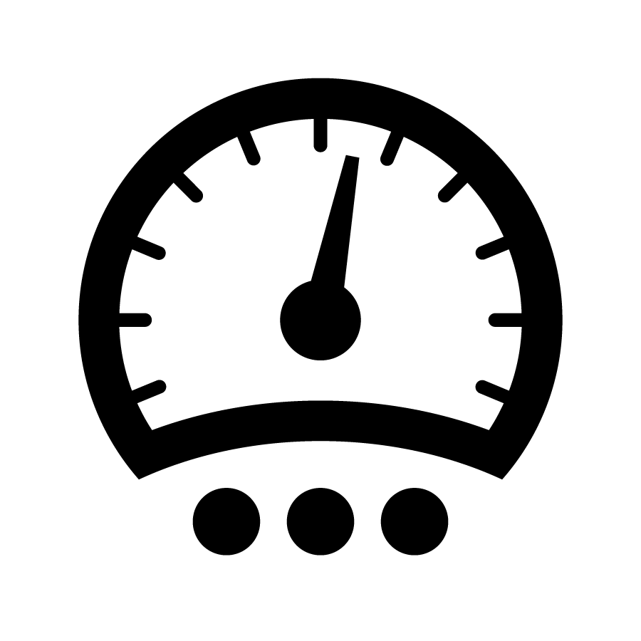
|
Gauge Screen Button | Press the Gauge Screen button to select from available screens. |

|
Map Button | Press the Map button to access the map, manage your rides and waypoints, and to see your friends on the map with Group Ride. |

|
Phone Button | Press the Phone button to access your Bluetooth® connected phone, including recent calls, contacts, dialer, and messages. |

|
Audio Button | Press the Audio button to access the Radio, Weather, USB, and connected Bluetooth® music interface |

|
Volume Decrease Button | Press the Volume Decrease button to decrease the volume. Press and hold to mute volume. |

|
Volume Increase Button | Press the Volume Increase button to increase the volume. |
The optional PIN Activated Security System (P.A.S.S.) is to prevent unauthorized use. When enabled, the vehicle cannot be operated until a valid passcode has been entered using the Ride Command display screen.
Go the settings menu by pressing the Menu button.
Select Vehicle Settings from the left toolbar.
Select Key Switch Lockout.
If this your first time activating P.A.S.S. you will be prompted to enter a new passcode. Enter and verify new passcode.
Please record your passcode.
Turn Key Switch Lockout from No to Yes.
Turn off the vehicle using the key switch.
Go the settings menu by pressing the Menu button.
Select Vehicle Settings from the left toolbar.
Select Key Switch Lockout.
Enter passcode to disable P.A.S.S.
Turn Key Switch Lockout from Yes to No.
| Icon | Driveline Mode | Description |
|---|---|---|

|
All Wheel Drive (AWD) Lock |
When in All-Wheel Drive Lock, the front drive is engaged with the front differential in the locked state. The locked state drives all wheels at the same speed which will increase steering effort and changes the handling characteristics from the AWD mode. If switched to AWD Lock when vehicle speed and accelerator pedal position are above activation limits, AWD Lock will not engage until vehicle speed and accelerator pedal position are decreased. |
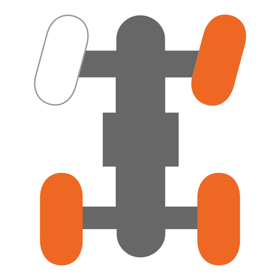
|
All Wheel Drive (AWD) Unlock |
When in All-Wheel Drive, the front drive is engaged with the front differential in the open state. The open state allows the front wheels to spin at different speeds for improved turning ability. If switched to AWD Unlock when vehicle speed and accelerator pedal position are above activation limits, AWD Unlock will not engage until vehicle speed and accelerator pedal position are decreased. |
|
Two-Wheel Drive (2WD) | When the switch is set to 2WD the vehicle is in two-wheel drive at all times. |
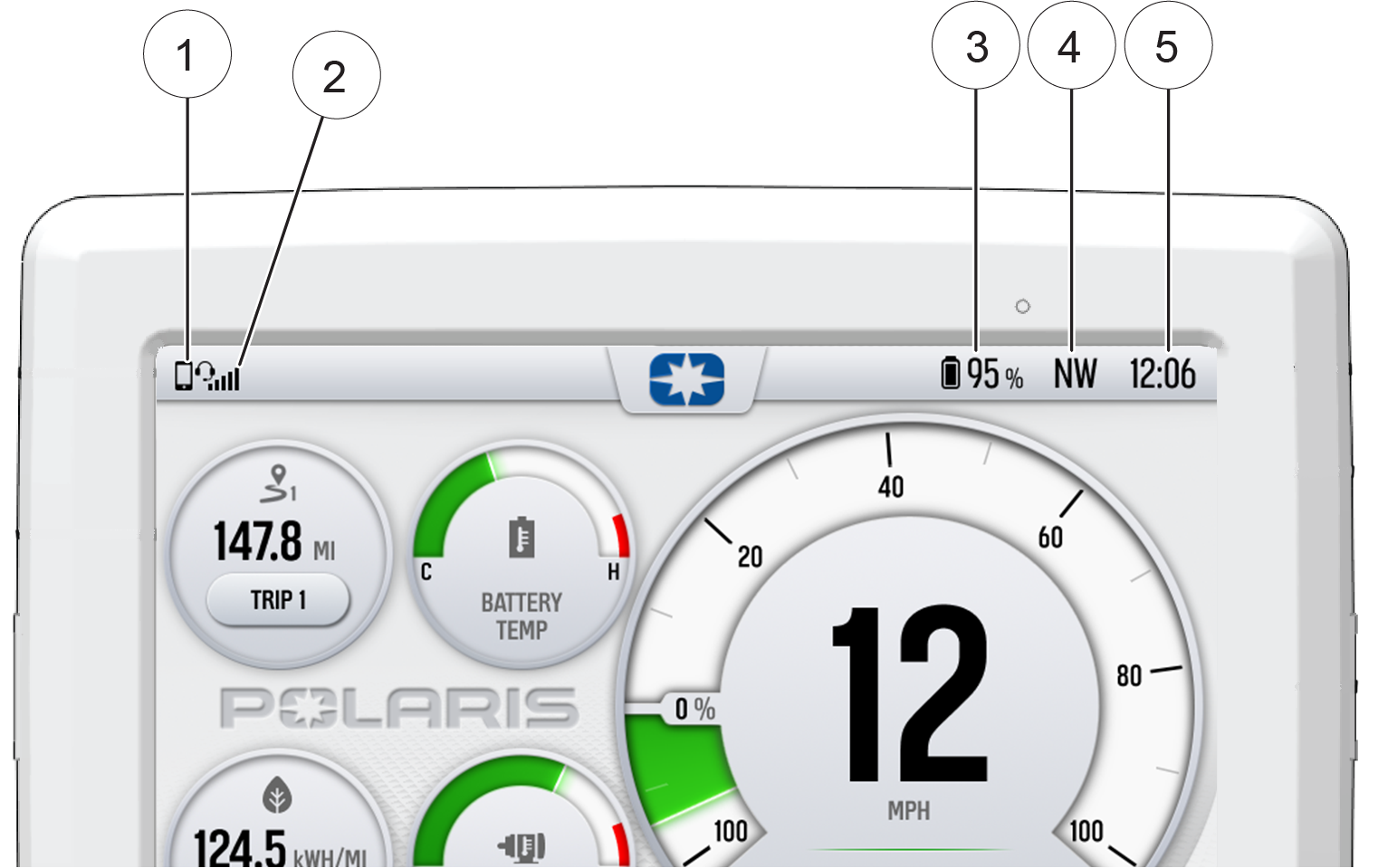
| Icon | Description | Function |
|---|---|---|
| 1 | Headset | Displays icon if headset is connected |
| 2 | Signal Strength | Displays current cell signal strength |
| 3 | Charge Level | Displays current charge capacity percentage |
| 4 | Vehicle Direction | Displays vehicle direction |
| 5 | Clock | Displays current time |
Press the Gauge Screen button to toggle between gauge screens. The display comes loaded with two different gauge screens. Additional gauge screens can be added or deleted.
Each gauge screen is customizable and can be set up in the following configurations:
Four round widgets
Two round widgets and a list of three data values
A list of five data values
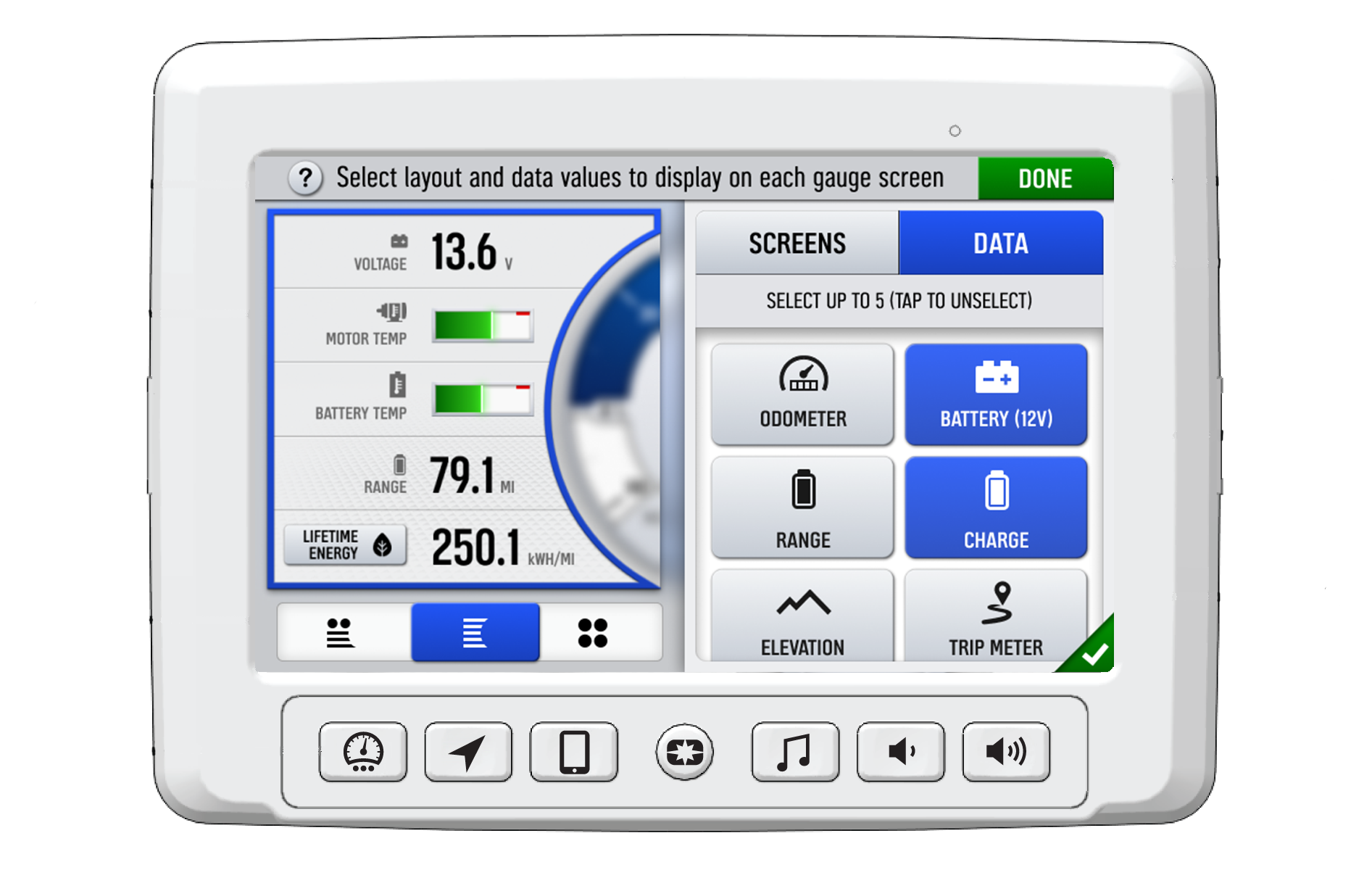
From the setting menu you can view vehicle information, manage Bluetooth® devices, update display software, and more.
To access the Setting menu, press
the Menu button 1.
You can
also navigate to the settings menu by pressing the Polaris logo at
the top of the display screen 2. This will open the Control
Panel. From the Control Panel, select the settings tab, then press
the All Settings button located in the lower right corner of
the display screen.
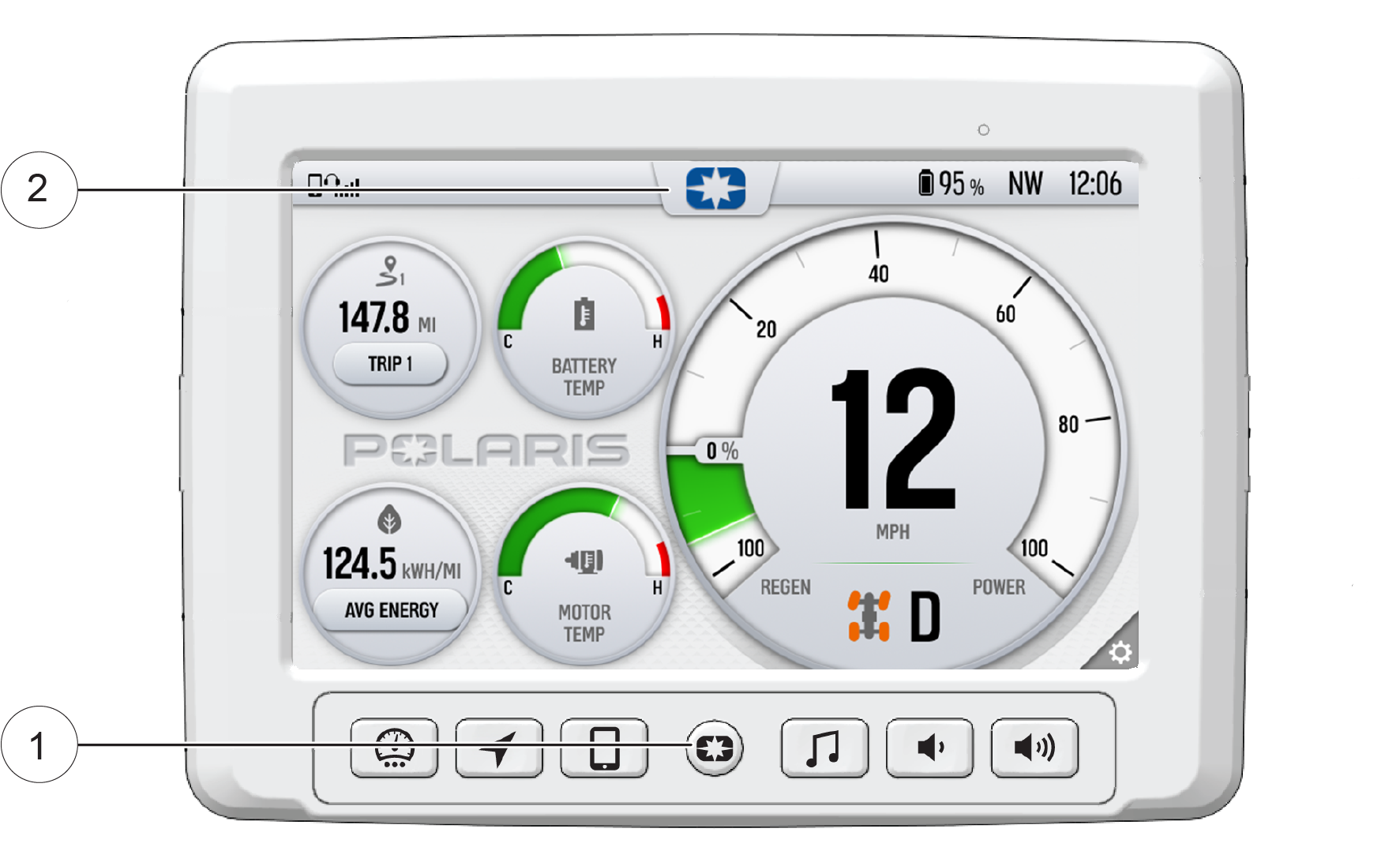
From the Menu settings, select the display mode from the available options.
The display mode can be set to Day, Night, or AUTO mode.
Day Mode
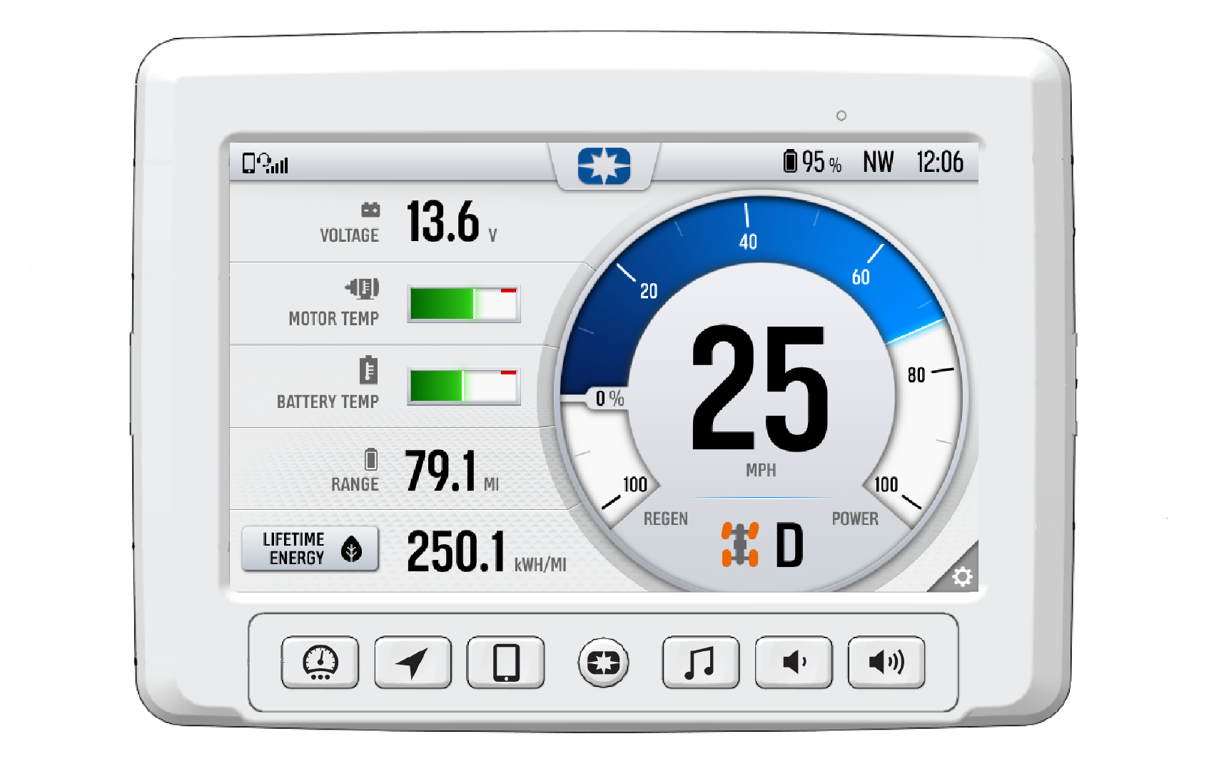
Night Mode
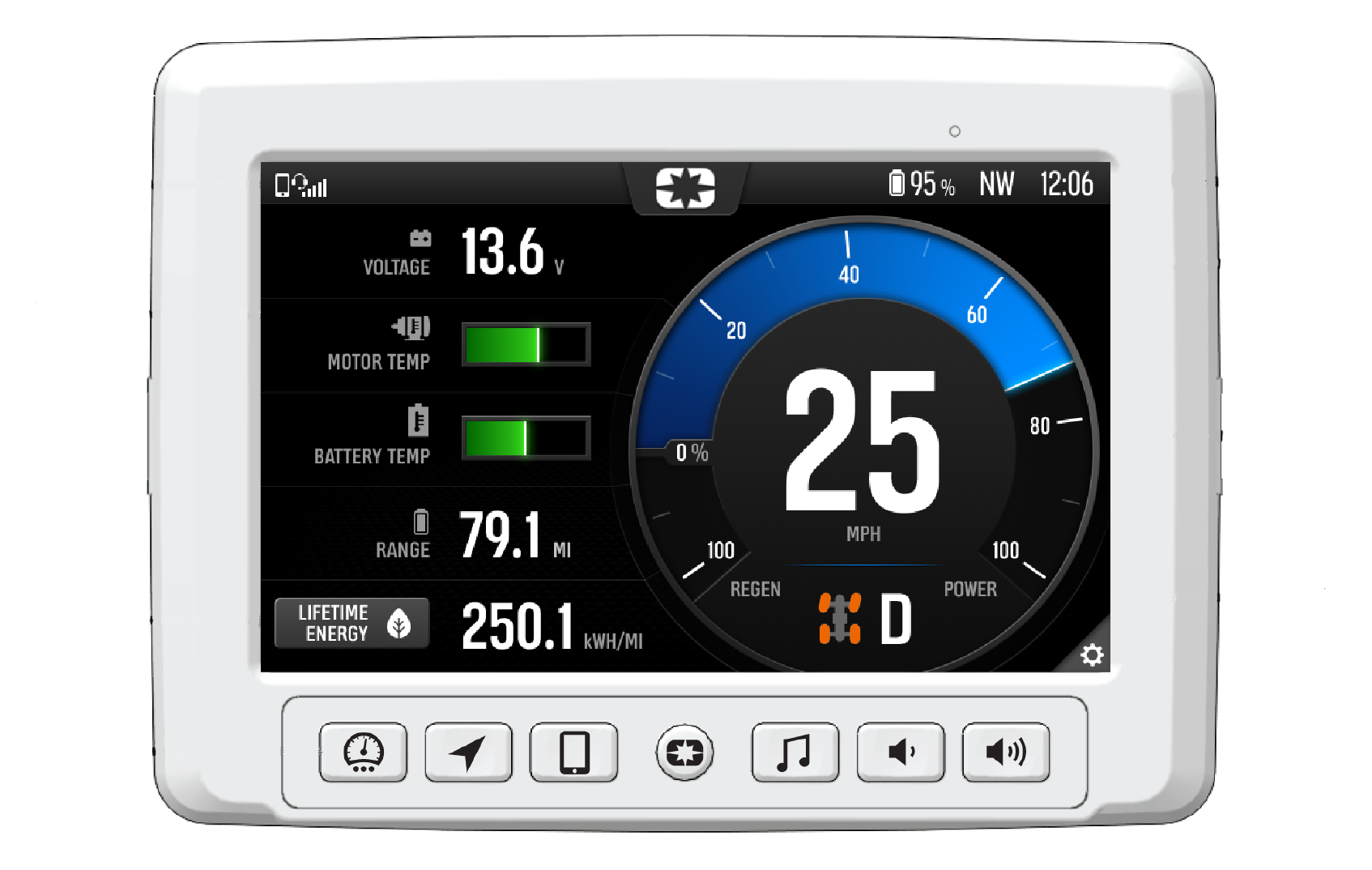
For managing updates via USB flash drive, the USB cable is located in the glove box.
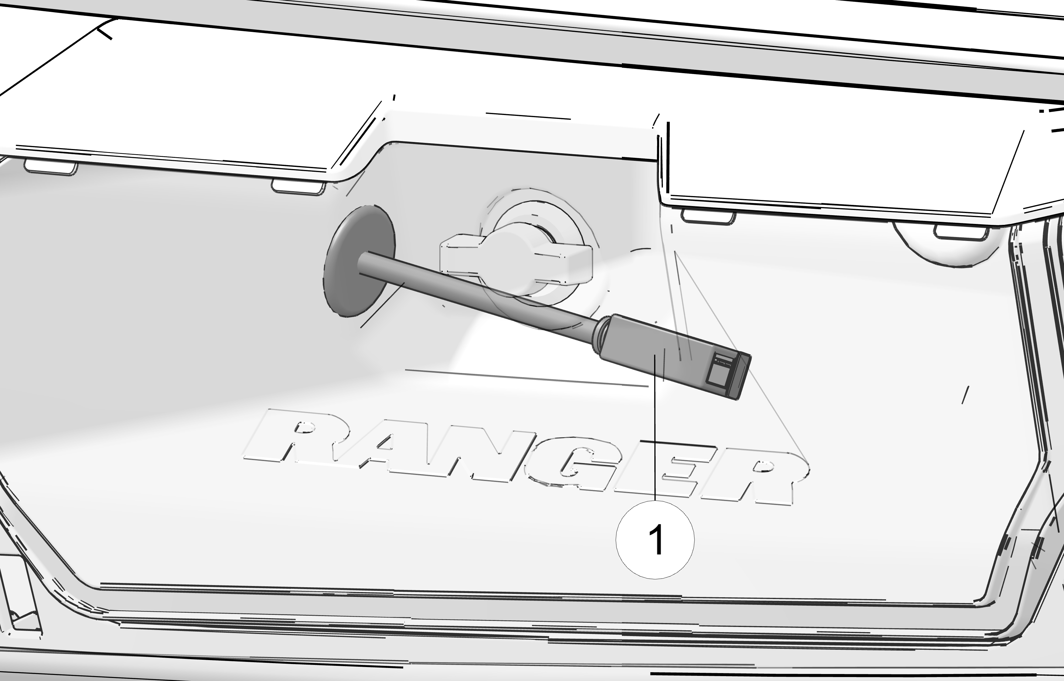
To update the software, do the following:
Go to ridecommand.polaris.com/display .
Log into your account, or create a new account.
Using the Vehicle Identification Number (VIN), add your new Polaris vehicle to your Garage.
Locate and download the latest software to a USB flash drive (8+ GB).
Connect the USB flash drive to the USB cable and power up your vehicle.
On the RIDE COMMAND display, select the Settings menu on your display by pressing the POLARIS icon at the top of the screen.
Select General Settings, then Update Software.
Select the file you wish to load (use date listed in the file name to determine most recent file).
Select Yes to restart display (restart required).
If an error occurs while updating your software, perform one or all of the following actions to resolve the issue:
Remove and reconnect the USB flash drive securely.
Make sure the display files are not inside a folder on the flash drive.
Make sure only display files are on the flash drive. Remove any other files if necessary.
Try using a different USB flash drive.
To update the maps on your display, do the following:
Go to ridecommand.polaris.com/display and download the map update to a USB flash drive.
Insert USB flash drive into the USB port on your vehicle.
Press the Update maps in the General Settings.
Select the file you want to install by pressing the corresponding down arrow icon.
This will update the display’s map which will automatically restart the display once the update is complete. Do not remove the USB flash drive until the display has fully restarted.
For software update, POLARIS recommends using a SanDisk® or similar USB flash drive with a minimum of 4GB in available memory, formatted using the FAT32 or exFAT® file systems. For best results remove all files from the flash drive before starting the update process.
For Map updates, a 32GB USB drive is required (USB 3.0 drive is highly recommended) USB drive must be formatted to exFAT® before copying the map file onto it.
For Trail updates, a 4GB drive formatted to FAT32 can be used.
Your vehicle may come equipped with RIDE COMMAND+ technology, which gives you access to your vehicle’s custom information including Vehicle Health, Vehicle Locator and Issue Diagnostics along with a variety of features via the Polaris mobile app. You will need a cellular connection to view these features.
To learn more about RIDE COMMAND+, including equipped or compatible vehicles, specific features, and to access the RIDE COMMAND+ User Guide, visit ridecommand.polaris.com/ridecommand+ or scan the QR code below:

Disclaimer: RIDE COMMAND+ only available in North America.
Apply only moderate braking force for the first 50 stops. Aggressive or overly forceful braking when the brake system is new could damage brake pads and rotors.
Sit in the driver's seat and fasten the seat belt. Always make sure all cab nets are closed and latched when riding in this vehicle. Do not press the accelerator pedal while starting the vehicle.
Shift the gear selector to PARK (P) position.
Insert the key and turn the key switch to the ON position.
Press the Direction Selector Switch in the FORWARD (F) position to go forward or the REVERSE (R) position to go rearward. Always check the position of the Direction Selector Switch (F/R) before pressing the accelerator pedal.
Shift the gear selector to either HIGH (H) or LOW (L) gear.
Press the accelerator pedal to move the vehicle.
Release the accelerator pedal completely.
Press on the brake pedal evenly and firmly.
Practice starting and stopping (using the brakes) until you're familiar with the controls.
Before switching to reverse, use extra care to make sure the area is clear of people or obstacles. When it’s safe to proceed, back slowly.
Follow these precautions when operating in reverse:
Always check for obstacles or people behind the vehicle.
Apply pressure to the accelerator pedal lightly. Do not press the accelerator pedal suddenly.
Back slowly.
Apply the brakes lightly for stopping.
Avoid making sharp turns.
To park the vehicle:
Stop the vehicle on a level surface.
Place the transmission in PARK (P). This vehicle can roll whenever the transmission is not in the PARK (P) position.
Stop the motor by turning the Key Switch from the ON position to the OFF position..
Engage the park brake (if equipped).
Remove the key to prevent unauthorized use.
When the high-voltage battery pack reaches 20-25% remaining charge, the vehicle will display LOW CHARGE on the instrument cluster. As the battery pack discharges to a lower remaining charge (e.g. 5%), vehicle performance may gradually decrease in order to conserve power. There will be less available power and torque while operating with low charge.
Move vehicle to a firm level surface.
Shift to PARK (P).
Do not leave engine running.
Prevent the vehicle from moving by chocking the wheels. A chock is a wedge or wheel stop that is designed to keep the vehicle from moving forward or backward and falling off the jack. If jacking the FRONT of the vehicle, then chock front and rear sides of both REAR tires. If jacking the REAR of the vehicle, then chock front and rear sides of both FRONT tires.
Keep bystanders away and make sure no occupants or cargo are still in the vehicle.
Use a jack designed for a high ground clearance off-road vehicle (such as the POLARIS Off-Road Utility Jack).
Follow the jack manufacturer's instructions.
Do not place any object above or under a jack.
After lifting vehicle with a jack, never place any part of your body under the vehicle without first properly blocking vehicle using designated support points.
Any qualified repair shop or person may maintain systems on your vehicle. An authorized Polaris dealer can perform any service that may be necessary for your vehicle.
Owners are responsible for performing the scheduled maintenance identified in this owner’s manual.
Careful periodic maintenance will help keep your vehicle in the safest, most reliable condition. Inspection, adjustment and lubrication of important components are explained in the periodic maintenance chart.
Inspect, clean, lubricate, adjust and replace parts as necessary. When inspection reveals the need for replacement parts, genuine Polaris parts are available from your Polaris dealer.
Service and adjustments are important for proper vehicle operation. If you’re not familiar with safe service and adjustment procedures, a qualified dealer can perform these operations.
Vehicles subjected to heavy or severe use patterns must be inspected and serviced more frequently.
Frequent exposure to mud, water, or sand
Racing or race-style use
Sustained operation at high speeds
The intervals shown in this table are based on vehicles operated
under normal conditions. Each interval is given in miles (kilometers)
or time intervals. Items should be serviced at whichever interval
comes first. Continue to reference the following maintenance schedules
at the given intervals as miles (kilometers) or time in use increases
on the vehicle.
Vehicles subjected
to severe use must be serviced at 50% of the stated interval. Examples
of Severe Use: Frequent exposure to mud, water, or sand, prolonged
high-speed use, prolonged low-speed heavy load operation.
| Every 1000 Miles (1600 km) | |
|---|---|
| Vehicle Body | Clean throughout the vehicle using mild soap and water (such as from a garden hose) to remove dirt and/or debris. Caked-on debris like mud should be removed by hand. Do not use high-pressure water. Allow vehicle to dry before operating.. |
| 12V Battery | Check terminals; terminals should be tight and free of corrosion. Clean, test, and replace as necessary. |
| High-voltage Cables | Visually inspect high-voltage cabling (orange color) for damage to insulation, proper routing, and proper retention. If damage is suspected, have vehicle brought immediately to an authorized dealer. |
| Front Gearcase Fluid | Change fluid. |
| Brake System | Inspect for fluid leaks; add lubricant if needed. Inspect brake pad wear. |
| Wiring | Inspect for wear, routing, and retention. |
| General Lubrication | Locate all applicable fittings and grease. |
| Suspension / Steering Components* | Inspect tie rods, wheel bearings, suspension bushings, and ball joints for loose or worn components; replace as needed. Inspect shock absorbers for leaks or damage. Lubricate (if applicable). |
| Cooling System | Fluid level inspection; inspect for fluid leaks; add coolant if needed. Inspect coolant strength seasonally. |
| Transmission Fluid | Change fluid. |
| Parking Brake (if applicable) | Inspect and adjust as needed. |
| * It is recommended to have an authorized dealer perform these services. | |
Vehicles subjected to severe use must be serviced at 50% of the stated interval. Examples of Severe Use: Frequent exposure to mud, water, or sand, constant high RPM use, prolonged low-speed heavy load operation, extended idle, and short trip cold weather operation.
| Additional Maintenance Intervals | ||
|---|---|---|
|
Monthly |
Brake Pad Wear | Inspect and replace as needed. |
| 12V Battery | Check terminals; Test; Clean / Replace as needed. | |
|
Every 2000 miles (3200 km) or 24 months |
Brake Fluid | Change fluid (DOT 4). |
|
Every 2000 miles (3200 km) |
Shock Absorbers* | Replace. |
|
Every 5 years |
Cooling System | Replace fluid. |
| * It is recommended to have an authorized dealer perform these services. | ||
Check and lubricate all components at the intervals outlined in the Periodic Maintenance Chart section, or more often under severe use, such as wet or dusty conditions. Items not listed in the chart should be lubricated at the general lubrication interval.
| Item | Lube | Method |
|---|---|---|
| Brake Fluid | DOT 4 Brake Fluid | Maintain level between fill lines. See Brakes. |
| Transmission Gearcase Oil | AGL Gearcase Lubricant | See Transmission Oil Check. |
| Front Gearcase Oil | Demand Drive Fluid | See Demand Drive Oil Check. |
| Prop Shaft | U-Joint Grease | Locate fitting and grease. |
| Front and Rear Stabilizer Bar Bushings | All Season Grease or grease conforming to NLGI No. 2 | Grease one fitting on each side of the vehicle. |
Lubrication Points
1 Prop Shaft
2 Front Stabilizer Bar (both sides)
3 Rear Stabilizer Bar (both sides)
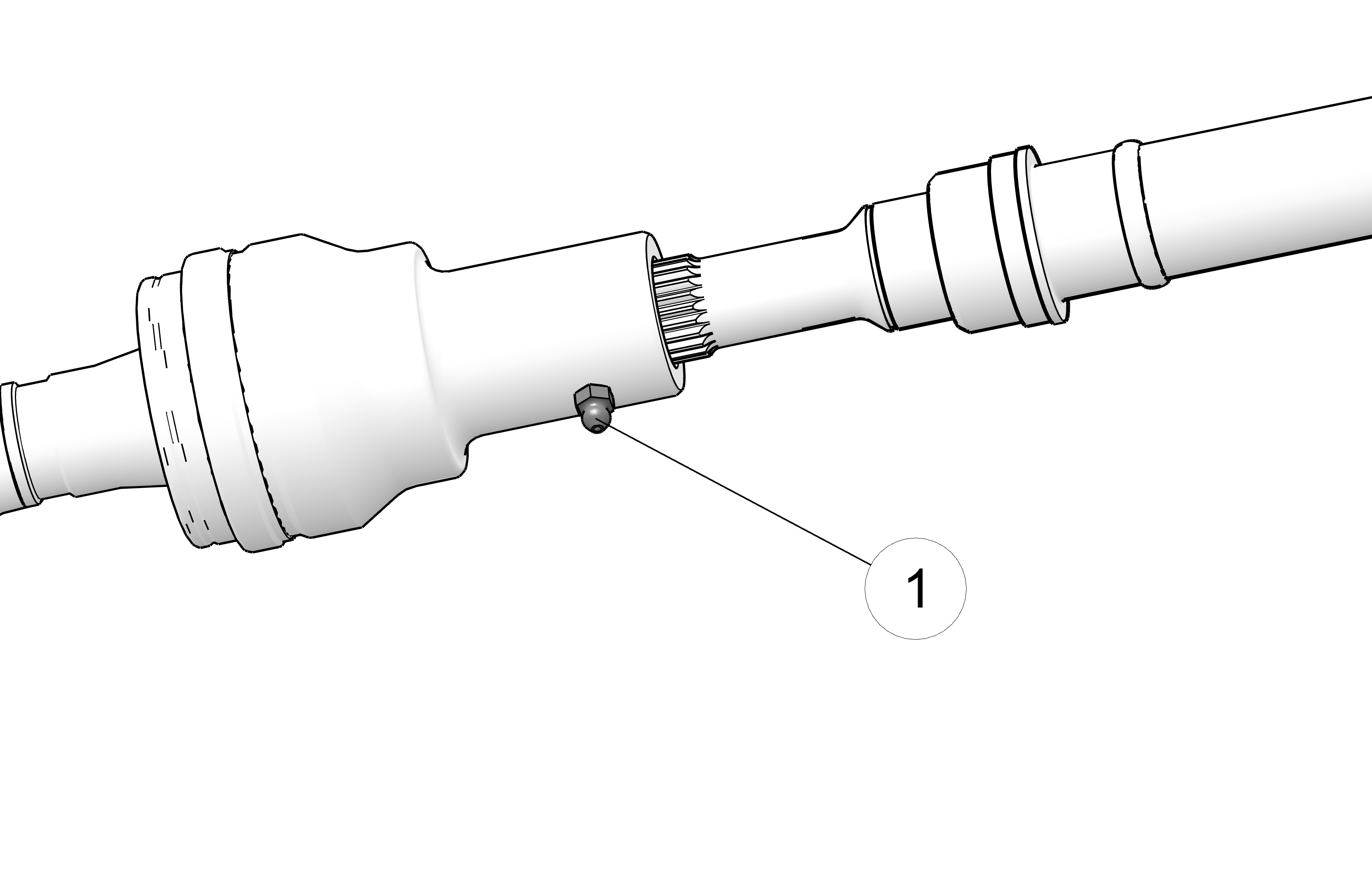
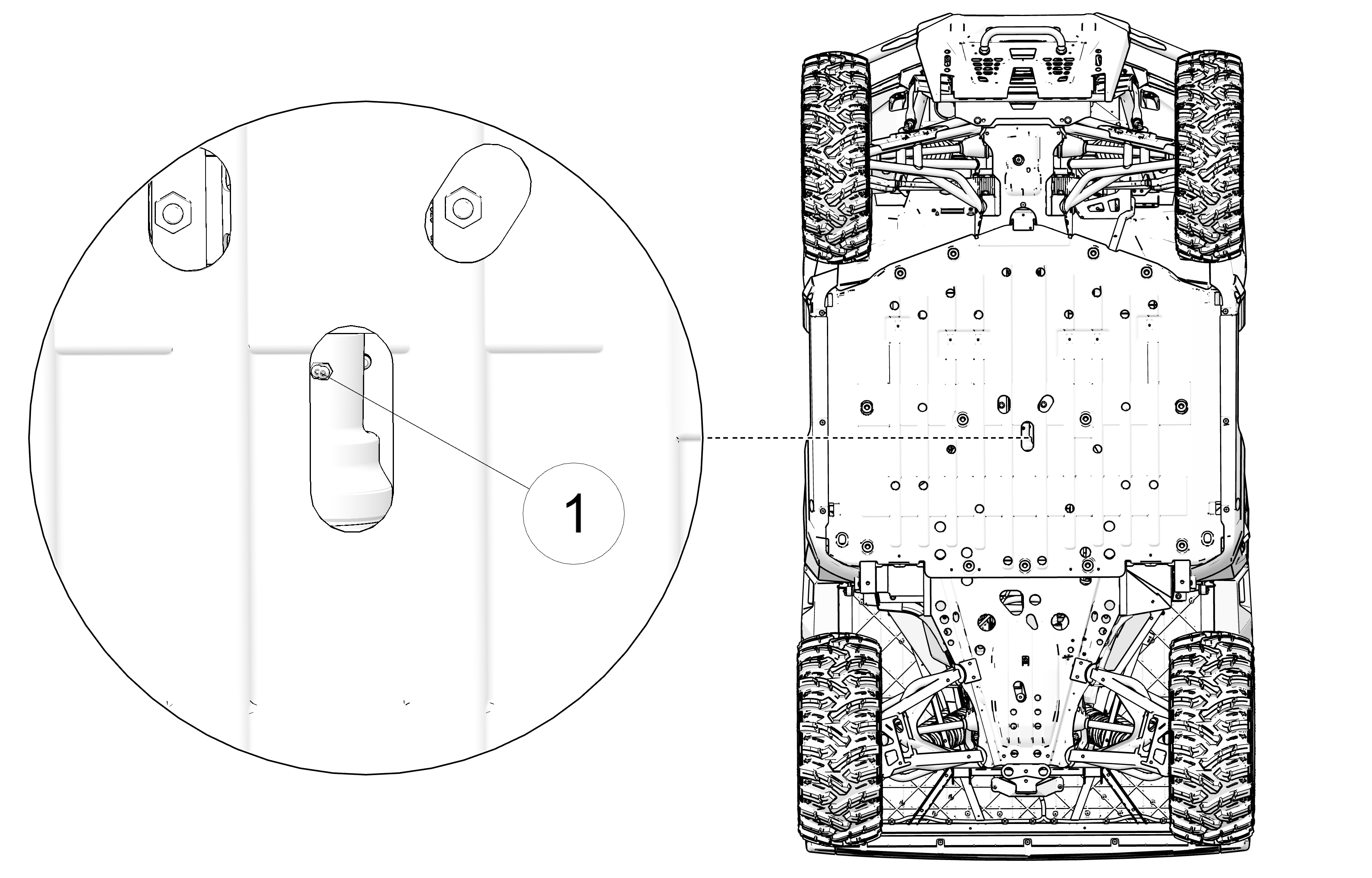
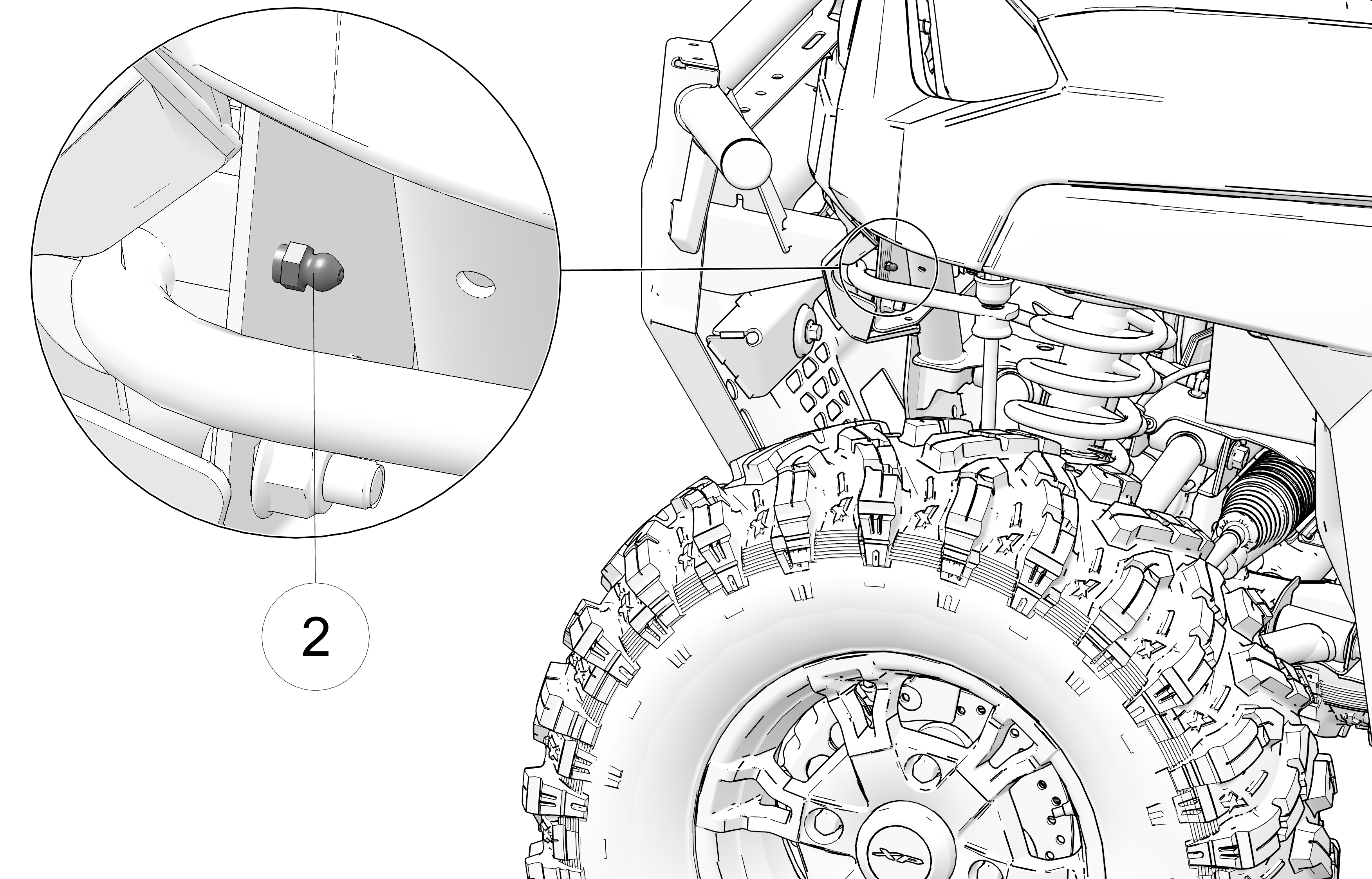
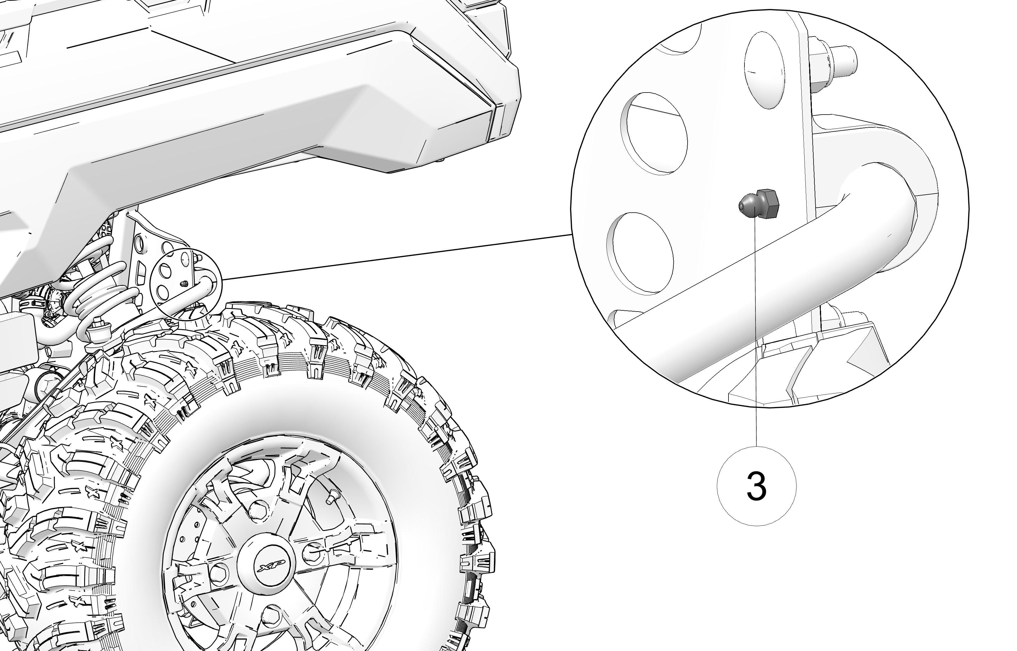
| Gearcase | Lubricant | Capacity | Fill Plug Torque | Drain Plug/ Level Check Plug Torque |
|---|---|---|---|---|
| Transmission (Main Gearcase) | AGL Gearcase Lubricant & Transmission Fluid | 51 oz. (1500 ml) |
10-14 ft. lbs. (14-19 Nm) |
10-14 ft. lbs. (14-19 Nm) |
| Demand Drive Unit (Front Gearcase) | Demand Drive Fluid | 6.8 oz. (200 ml) |
8-10 ft. lbs. (11-13.6 Nm) |
11 ft. lbs. (15 Nm) |
Always check and change the transmission oil at the intervals outlined in the Periodic Maintenance Chart. Maintain the oil level even with the bottom thread of the fill plug hole.
The fill plug is located on the rear of the gearcase. Maintain the fluid level at the bottom of the fill plug hole.
To check the transmission fluid, do the following: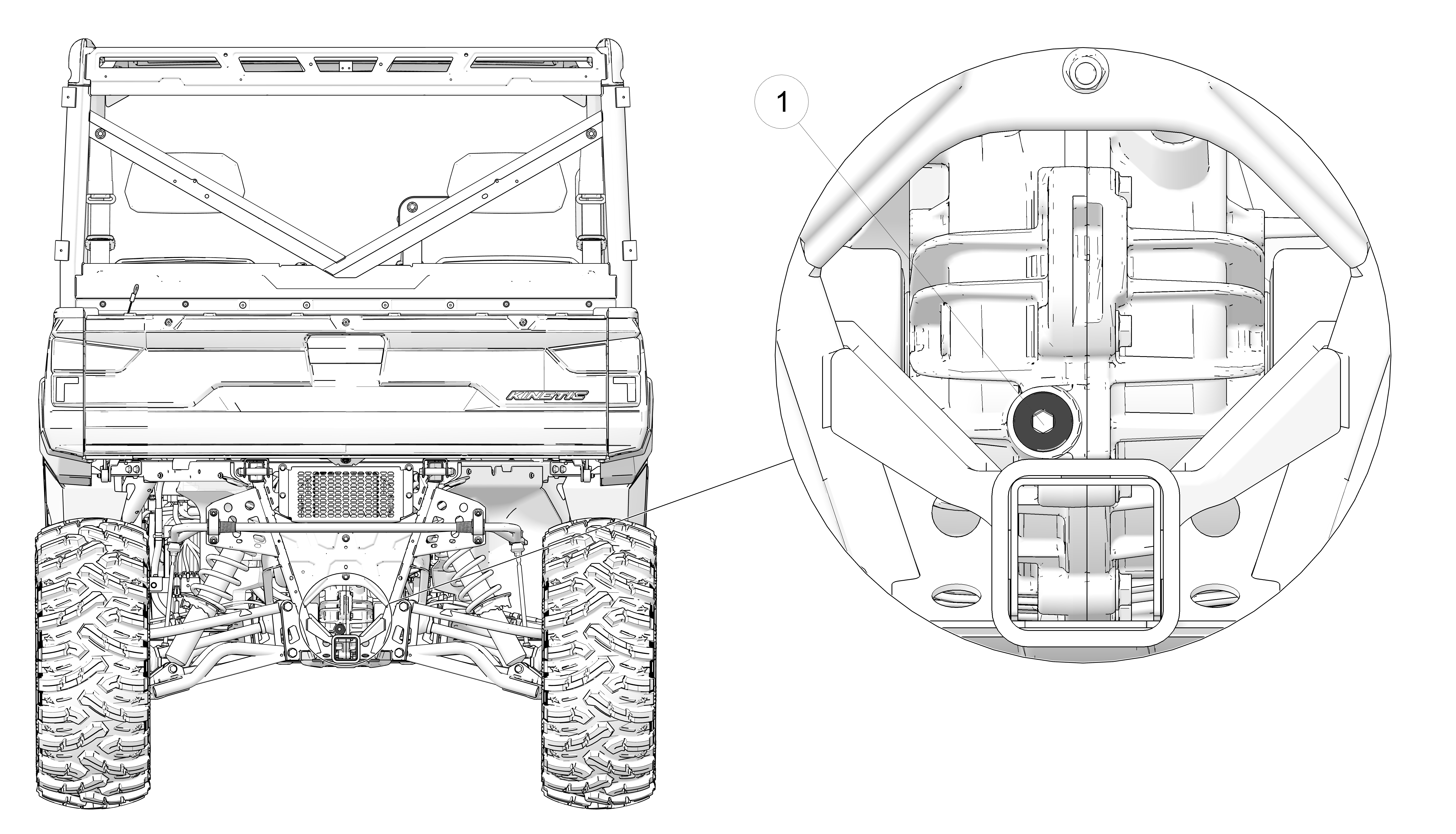
Position the vehicle on a level surface.
Remove the fill plug 1.
Check the fluid level.
Add the recommended fluid to the bottom of the fill plug hole. Do not overfill.
Reinstall the fill plug. Torque to specification. See the Gearcase Specification Chart section.
The drain plug is located on the bottom of the gearcase. Access
the drain plug through the hole in the skid plate.
Remove the fill plug.
Place a drain pan under the drain plug 2.
Remove the drain plug. Allow the fluid to drain completely.
Clean and reinstall the drain plug. Torque to specification. See the Gearcase Specification Chart section.
Add the recommended fluid to the bottom of the fill plug hole. Do not overfill.
Reinstall the fill plug. Torque to specification. See the Gearcase Specification Chart section.
Check for leaks. Discard used fluid properly.
Always check and change the demand drive fluid at the intervals outlined in the Periodic Maintenance Chart. Maintain the oil level even with the bottom thread of the fill plug hole. Refer to the Gearcase Specifications Chart for recommended lubricants, capacities and torque specifications.
The front gearcase fill plug 1 is located on the right side of the front gearcase.
Position the vehicle on a level surface.
Remove the fill plug 1. Check the oil level.
Add the recommended oil as needed.
Reinstall the fill plug. Torque to specification.

Support the vehicle securely with a jackstand.
Remove the front tire on the passenger's side for ease of access (optional).
Remove the fill plug.
Place a drain pan under the drain plug 2 on the bottom right-hand side.
Remove the drain plug. Drain the oil.
Clean and reinstall the drain plug. Torque to specification.
Add the recommended fluid to the bottom of the fill plug hole. Do not overfill.
Reinstall the fill plug. Torque to specification.
Check for leaks.
Discard used oil properly.
The coolant access is located under the cargo box. Check for leaks
periodically and add coolant as needed.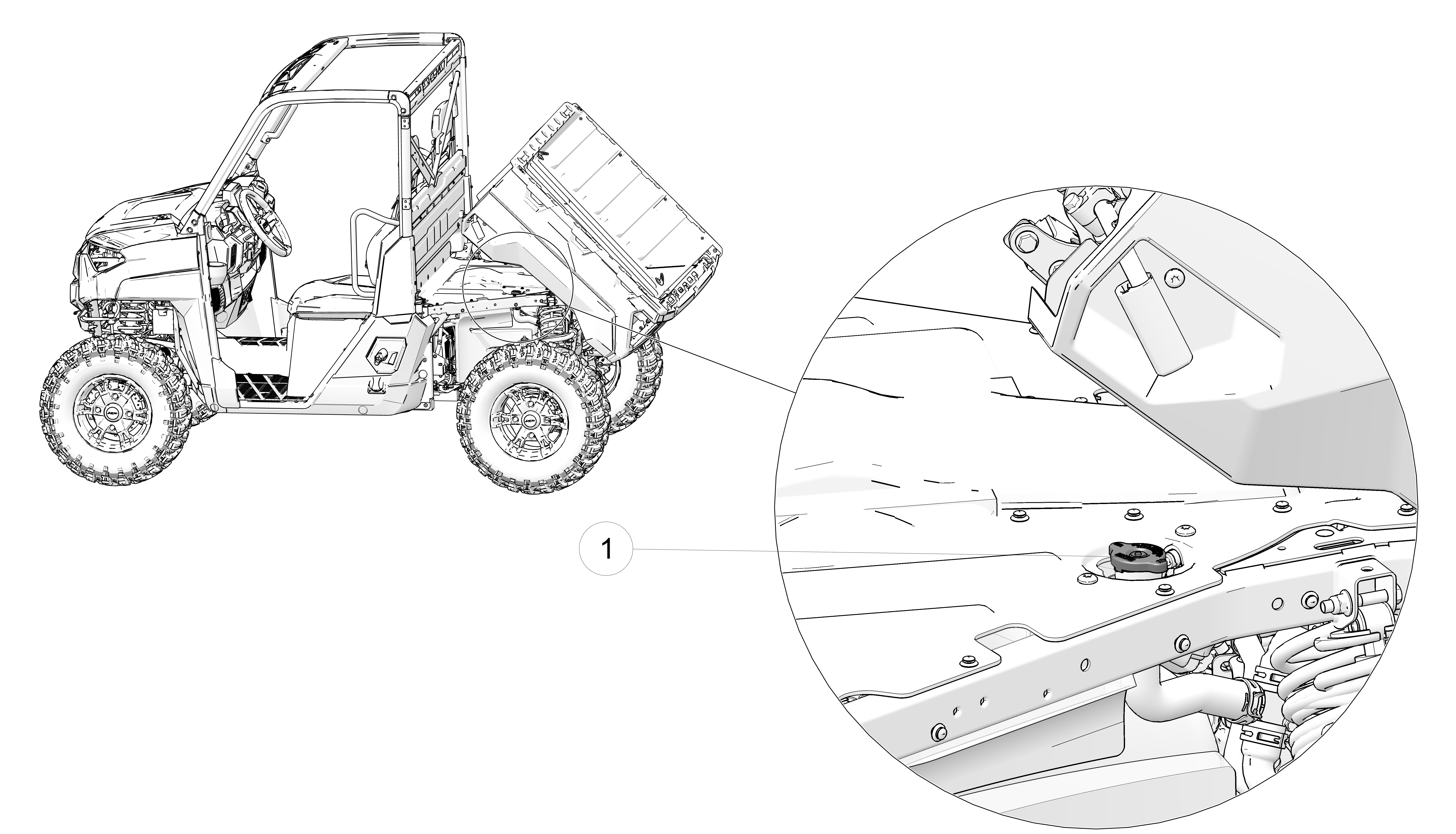
Lift the cargo box.
Slowly remove the radiator cap 1.
View the coolant level through the opening.
Use a funnel and slowly add coolant as needed.
Reinstall the pressure cap.
The front and rear brakes are hydraulic disc type brakes. Press down on the brake pedal to engage the brakes.
Inspect the brake system routinely. Inspect the level of the brake fluid before each operation.
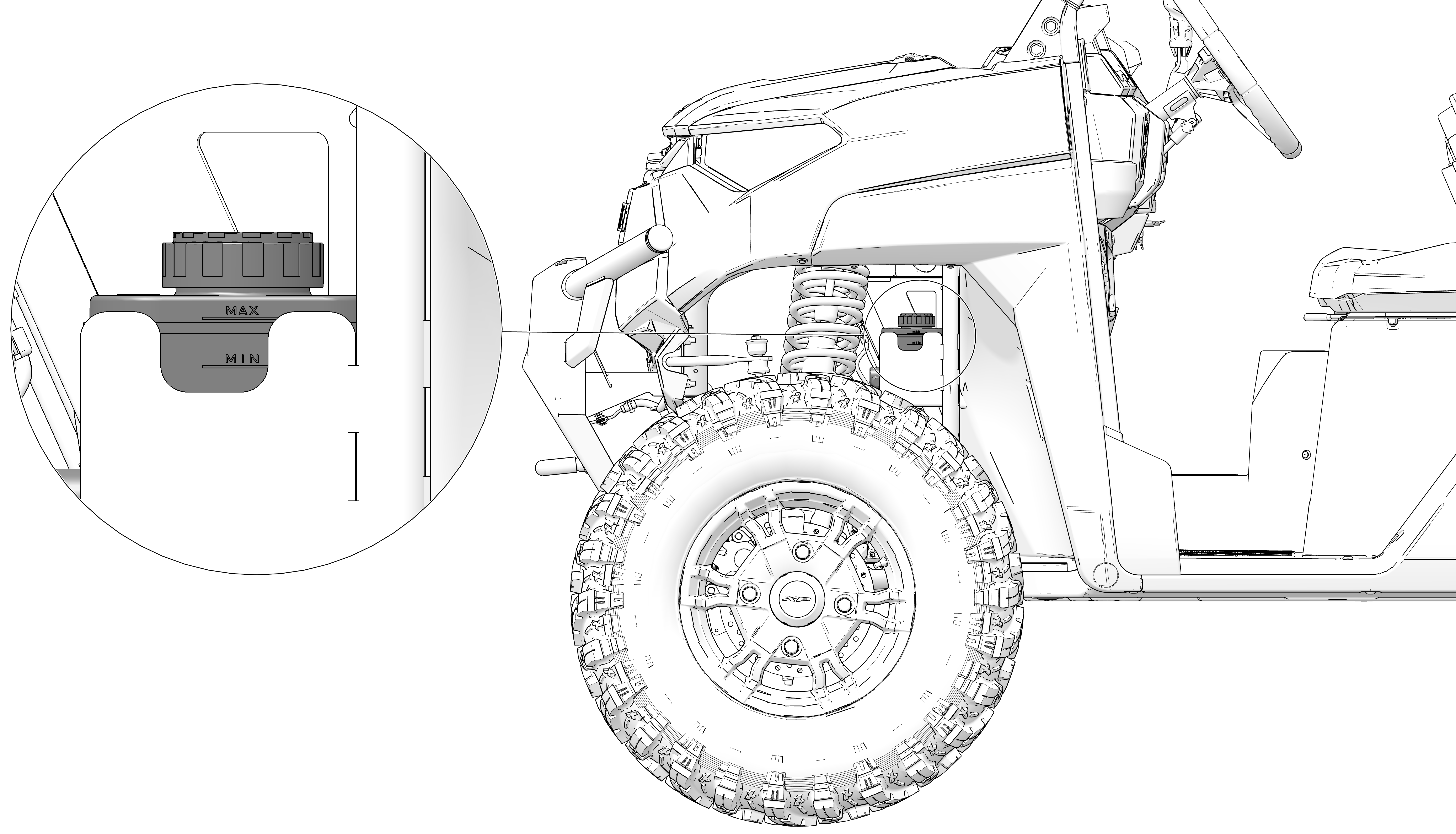
Change the brake fluid every two years and any time the fluid becomes contaminated, the fluid level is below the minimum, or if the type and brand of the fluid in the reservoir are unknown.
Position the vehicle on a level surface and turn off the motor.
View the brake fluid level at the reservoir in the driver’s side wheel well. The level should be between the upper (MAX) and lower (MIN) level lines.
If the fluid level is lower than the upper level line, open the hood and add brake fluid to the upper (MAX) line.
Apply the brake forcefully for a few seconds and check for fluid leakage around the fittings.
Do not apply WD-40® or any petroleum product to brake discs. These types of products are flammable and may also reduce the friction between the brake pad and caliper.
Check the brake system for fluid leaks.
Check the brake pedal for excessive travel or a spongy feel.
Check the friction pads for wear, damage and looseness.
Check brake discs for signs of cracks, excessive corrosion, warping or other damage. Clean any grease using an approved brake cleaner or alcohol.
Inspect the brake disc spline and pad wear surface 1 for excessive wear. Change pads when worn to 0.030 in (0.762 mm).
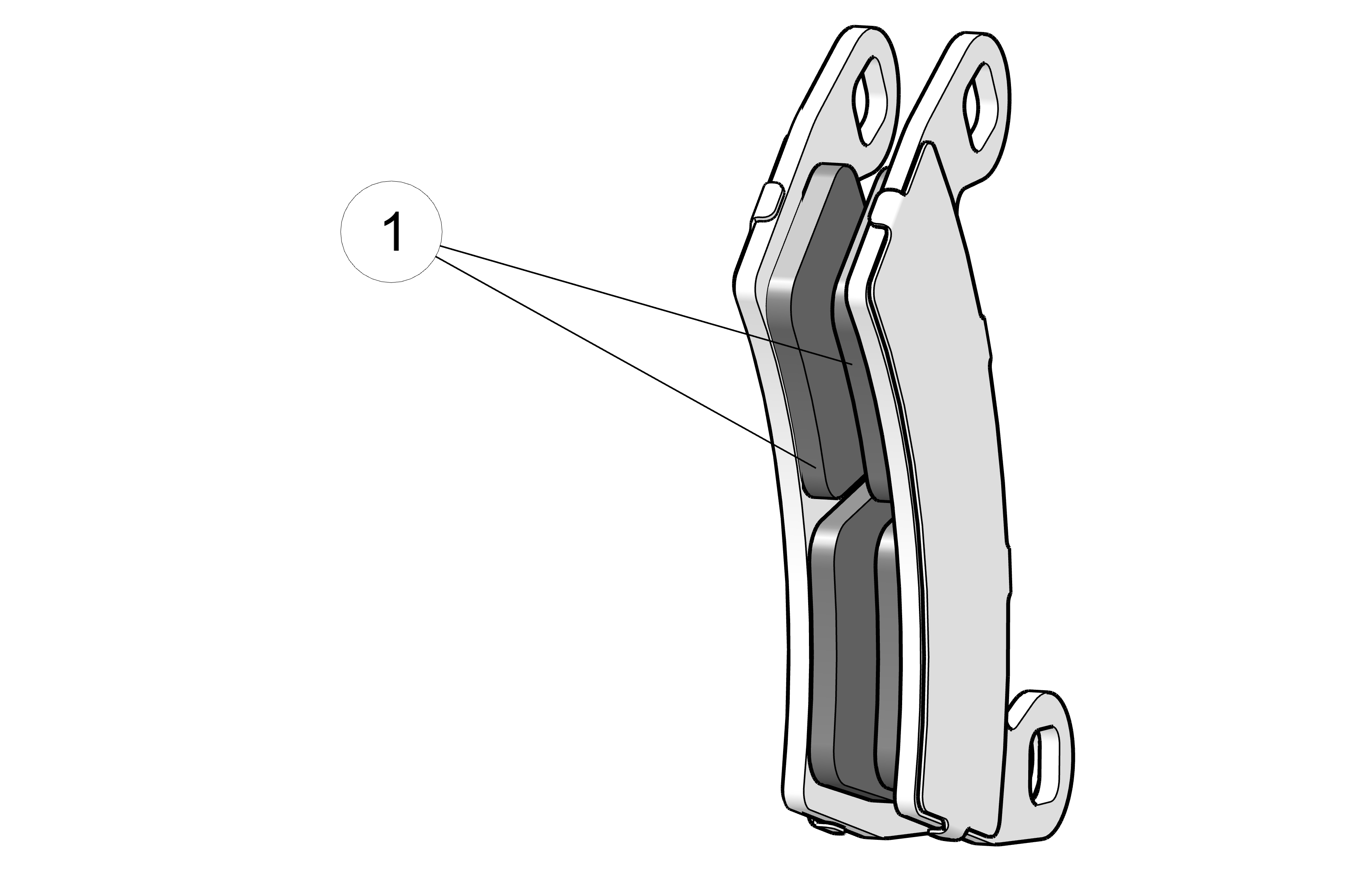
Check the steering wheel for specified freeplay and smooth operation at the intervals outlined in the Periodic Maintenance Chart section.
Position the vehicle on level ground.
Lightly turn the steering wheel left and right.
There should be 0.8-1.0 in (20-25 mm) of freeplay.
If there is excessive freeplay or strange noises, or the steering feels rough or “catchy,” have the steering system inspected by an authorized dealer.
The front suspension can be adjusted to provide a stiffer suspension, if necessary.
Support the vehicle securely with a jack stand.
Remove the top shock mounting bolts from the inside mounting positions 1.
Reposition the shocks to the outside mounting holes 2.
Reinstall the shock mounting bolts. Torque to 40 ft-lbs (54.2 N⋅m).
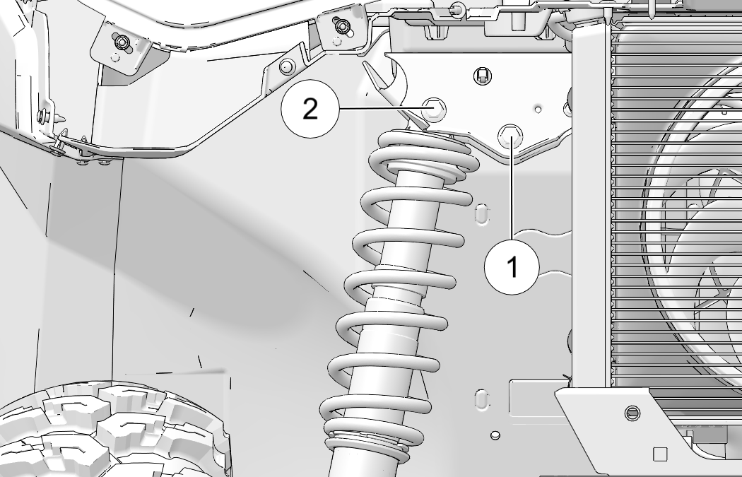
Adjust the front and rear shock absorber springs by rotating the adjustment cam either clockwise or counter-clockwise to increase or decrease spring tension.
1 Stiffest Setting
2 Softest Setting
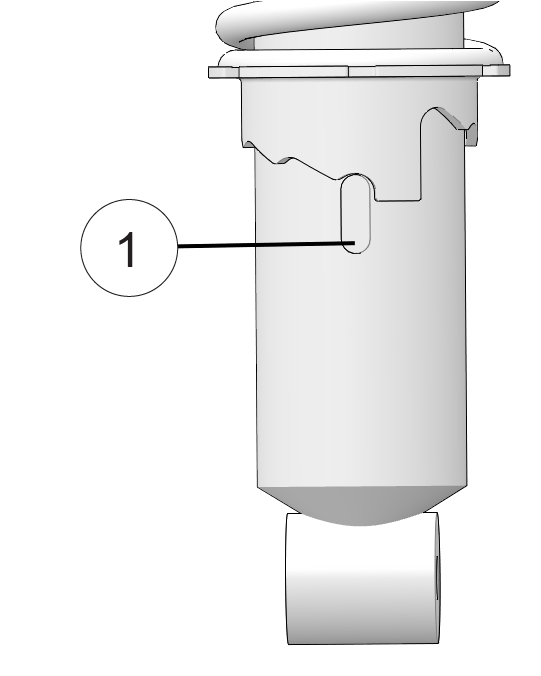
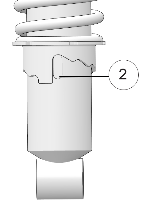
Always heed the following rules if you make adjustments to this suspension.
Always return the suspension to the lowest (softest) setting after the load is removed from the vehicle. The increased suspension height will negatively impact vehicle stability when operating without a load.
Always apply the same adjustment setting to both rear wheels.
Operating your vehicle with worn tires will increase the possibility of skidding, loss of control and an accident, which could result in serious injury or death. Always replace tires when the tread depth measures 1/8 in (3 mm) or less.
Improper tire inflation or the use of non-standard size or type of tires may adversely affect vehicle handling, which could result in vehicle damage or personal injury. Always maintain proper tire pressure. Always use POLARIS approved size and type of tires for this vehicle when replacing tires.
Always replace tires when tread depth is worn to 3 mm (1/8”) or less.
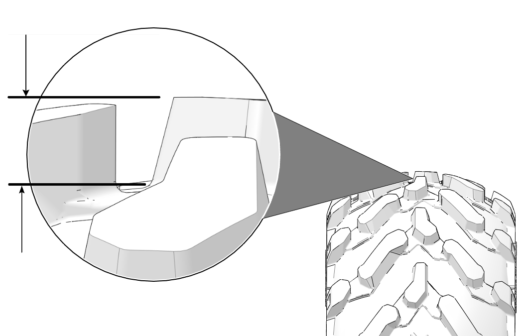
Inspect the following items occasionally for tightness, and if they've been loosened for maintenance service. Do not lubricate the stud or the lug nut.
| Lug Nut (Aluminum Wheels) |
|
Front and Rear | 120 ft-lbs (163 Nm) |
| Spindle Nut | Front | 180 ft. lbs. (245 N⋅m) | |
| Hub Retaining Nut | Rear | 180 ft. lbs. (245 N⋅m) | |
Position the vehicle on a level surface.
Apply the brakes. Set the park brake. Turn the key off.
Loosen the wheel nuts slightly.
Elevate the side of the vehicle by placing a suitable stand under the frame.
Remove the wheel nuts. Remove the wheel.
Place the transmission in PARK.
Place the wheel on the hub with the valve stem toward the outside and rotation arrows on the tire pointing toward forward rotation.
Attach the wheel nuts and finger-tighten.
Carefully lower the vehicle to the ground.
Torque the wheel nuts to specification.
The high-voltage service disconnect 1 is located under
the passenger-side seat. Lift the seat up and remove the storage bin
to access the harness.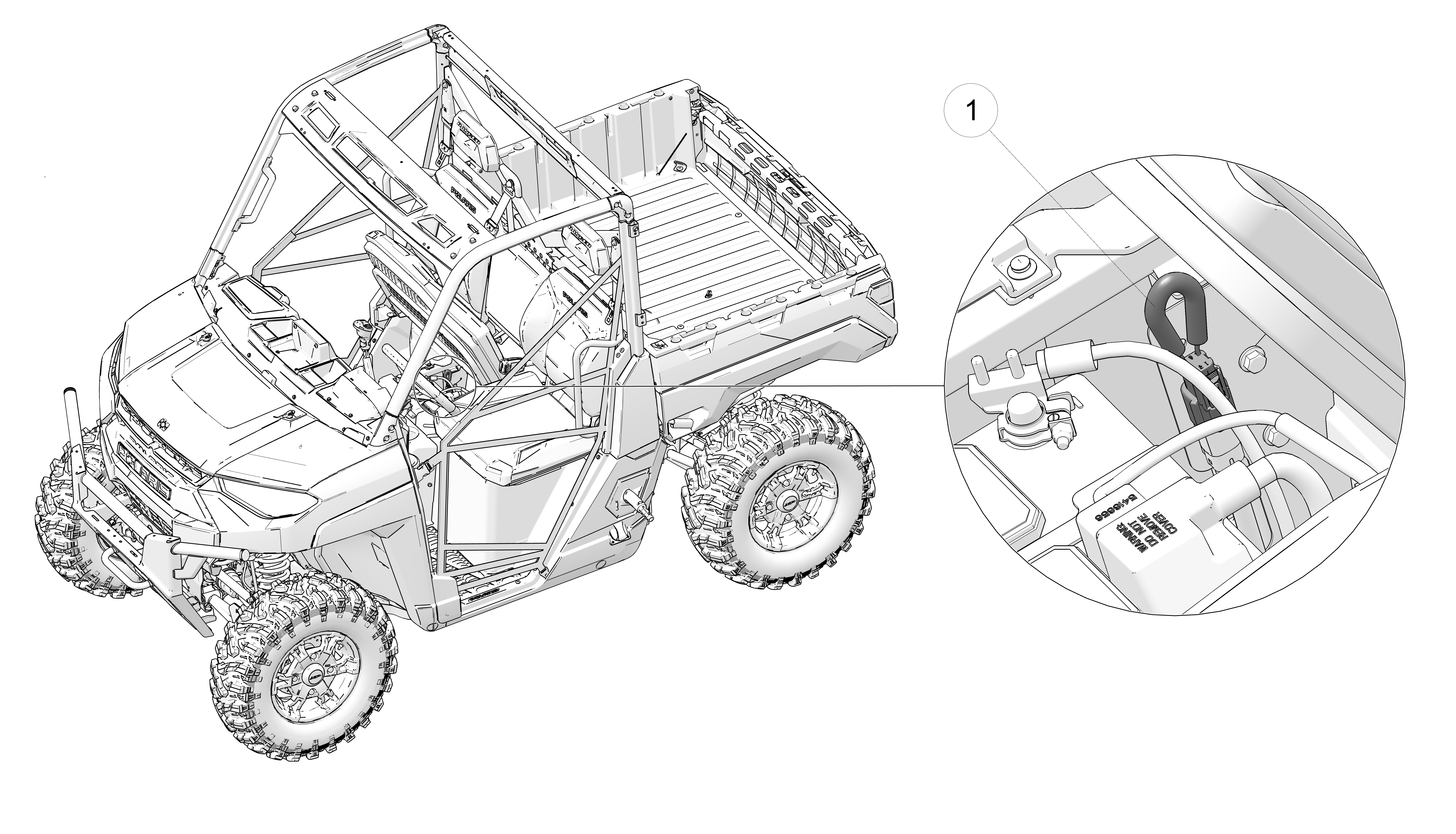
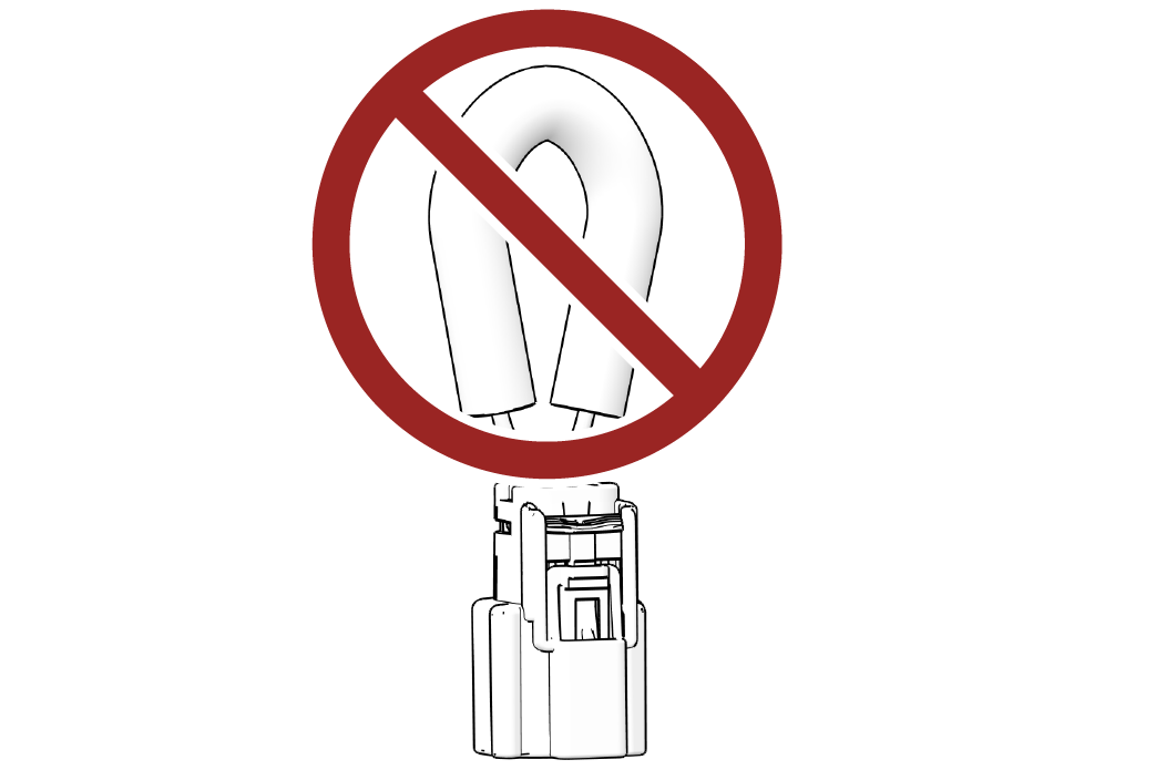
Slide the lock tab 2 up, pinch the secondary lock, and then pull the plastic housing from the harness. Reattach the housing to the harness and push the lock tab down when you have finished servicing the 12V battery to resume driving.
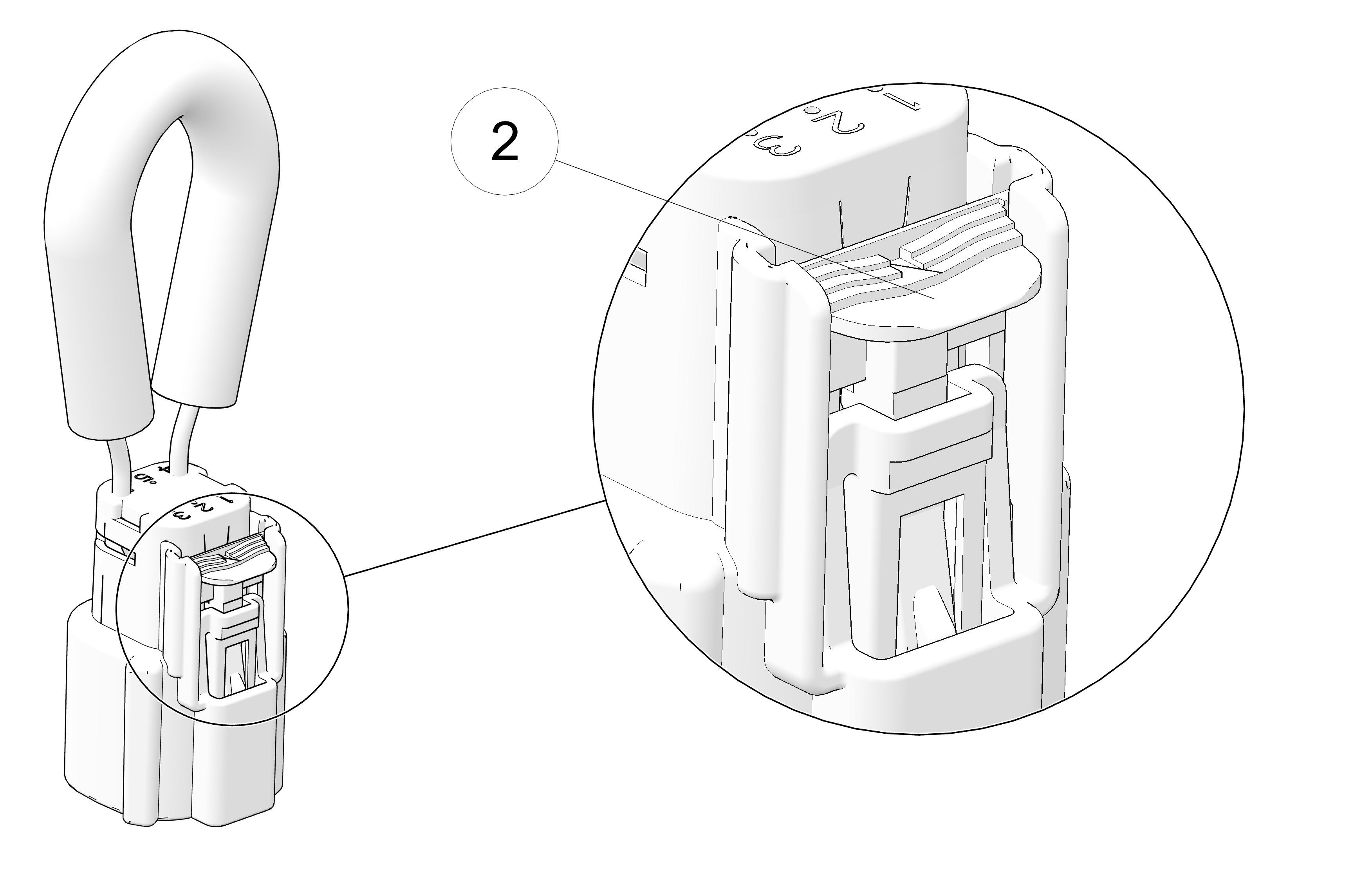
Battery electrolyte is poisonous. It contains sulfuric acid. Serious burns can result from contact with skin, eyes or clothing.
Antidote:
External: Flush with water.
Internal: Drink large quantities of water or milk. Follow with milk of magnesia, beaten egg, or vegetable oil. Call physician immediately.
Eyes: Flush with water for 15 minutes and get prompt medical attention.
Batteries produce explosive gases. Keep sparks, flame, cigarettes, etc. away. Ventilate when charging or using in an enclosed space. Always shield eyes when working near batteries. KEEP OUT OF REACH OF CHILDREN.
Before servicing your vehicle’s 12V battery, ALWAYS power off the vehicle and remove the key from the key switch. Then, ensure that high-voltage power is turned off by unclasping the high-voltage service disconnect.
Your vehicle has a low-maintenance flooded battery. It does not require refilling.
Always keep battery terminals and connections free of corrosion. If cleaning is necessary, remove the corrosion with a stiff wire brush. Wash with a solution of one tablespoon baking soda and one cup water. Rinse well with tap water and dry off with clean shop towels. Coat the terminals with dielectric grease or petroleum jelly. Be careful not to allow cleaning solution or tap water into a conventional battery.
The sealed battery is already filled with electrolyte and has been sealed and fully charged at the factory. Never pry the sealing strip off or add any other fluid to this battery.
Your electric vehicle will maintain the charge of the 12V battery whenever the High-Voltage Battery Pack has an adequate State of Charge (SoC). See Storing the Vehicle for details on long-term vehicle storage.
To remove the battery, do the following:
Power off the vehicle and remove the key from the key switch.
Lift up the passenger-side seat and remove the storage bin.
Remove the high-voltage service disconnect loop. See Disconnecting High Voltage Power for details.
Disconnect the black (-) battery cable first. Disconnect the red (+) battery cable last.
Remove the battery hold-down strap.
Lift the battery out of the vehicle.
Ensure that the battery is fully charged.
Place the battery in the battery holder.
Coat the terminals with dielectric grease or petroleum jelly.
Connect and tighten the red (positive) cable first.
Connect and tighten the black (negative) cable last.
Install the battery hold-down strap and tighten the screws.
Verify that cables are properly routed.
Reconnect the high-voltage service disconnect loop. See Disconnecting High Voltage Power for details.
Reinstall the seat and storage bin.
If the motor stops or will not start, or if you experience other
electrical failures, a fuse may need replacement. Locate and correct
any short circuits that may have caused the blown fuse, then replace
the fuse. To access the fuse box, lift the passenger-side seat up
and remove the storage bin under the seat. Spare fuses are provided
in the fuse box. If you suspect that a fuse or relay may not be working
properly, your dealer can assist.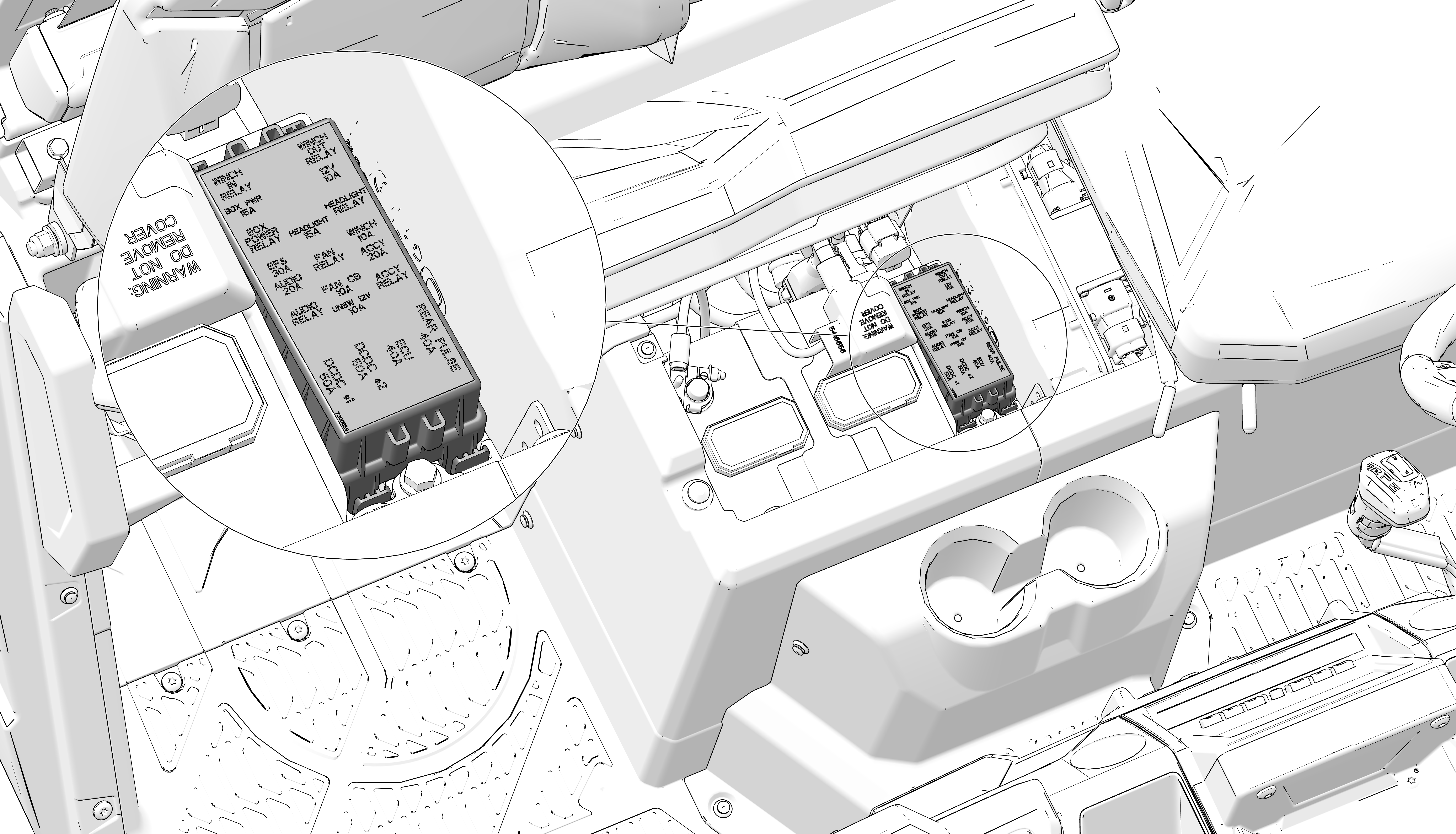
| Fuse Size | Feature Supported |
|---|---|
| 40A | Rear Pulse Bar |
| 40A | ECU |
| 50A | DCDC Converter (#1) |
| 50A | DCDC Converter (#2) |
| 15A | Box Power |
| 10A | 12V Accessory |
| 15A | Headlight |
| 30A | EPS |
| 10A | Winch |
| 20A | Audio |
| 20A | Accessory |
| 10A | Fan Circuit Breaker |
| 10A | UNSW 12V |
Poor lighting can result in reduced visibility when driving. Headlight and taillight lenses become dirty during normal operation. Clean lights frequently and replace failed (or failing) lights promptly. Do not operate this vehicle at night or in low light conditions until the headlight is replaced. Always make sure lights are adjusted properly for best visibility.
The vehicle is equipped with integrated LED lights. In the event of a failure, the entire assembly1 must be replaced.
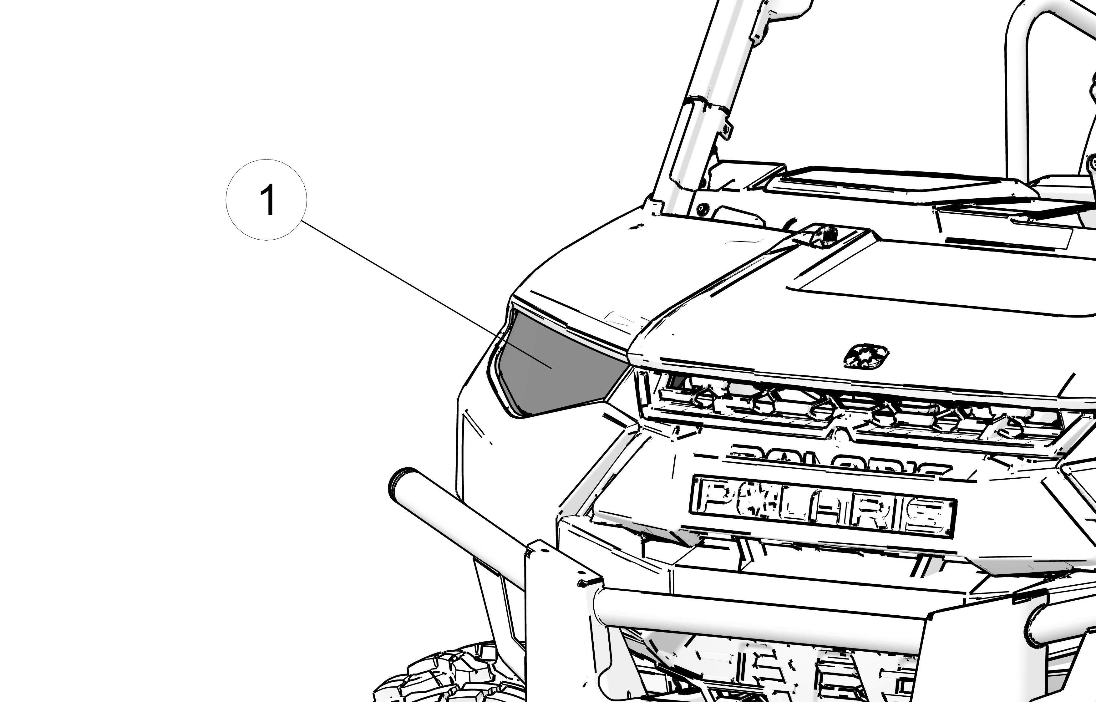
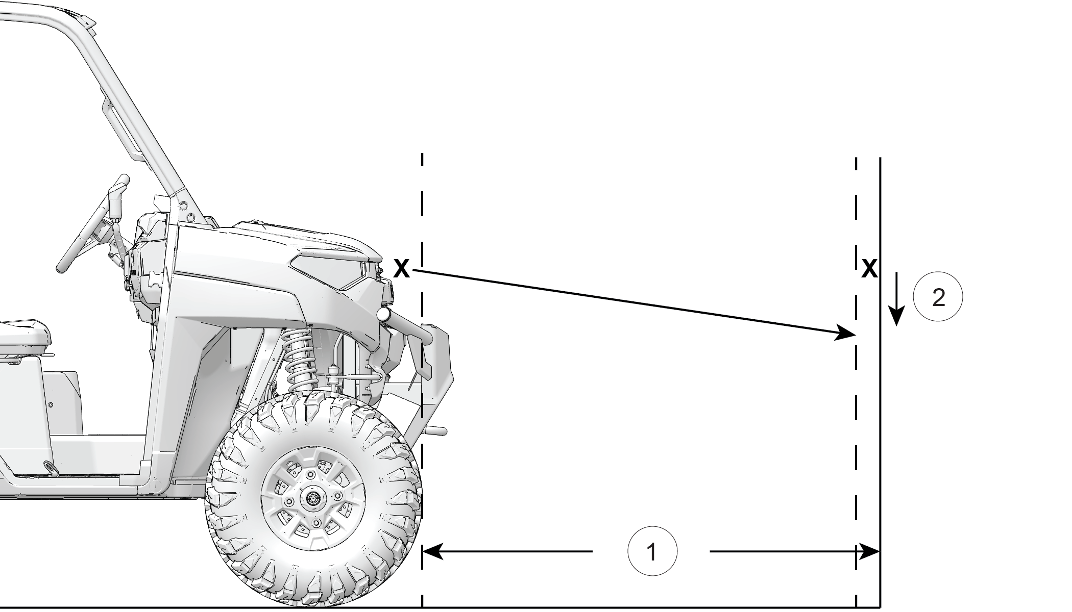
1 25 ft. (7.6 M)
2 8 in. (20 cm)
To adjust the headlight beam, do the following:
Ensure the tire pressure of all tires is at recommended levels.
Place the vehicle on a level surface with the headlight approximately 25 ft. (7.6 m) from a dark wall.
Measure the distance from the floor to the center of the headlight and make a mark on the wall at the same height.
Apply the brakes. Turn the key switch to ON position. Turn on the low-beam headlights.
Observe the headlight aim. The most intense part of the headlight beam should be aimed 8" (20 cm) below the mark placed on the wall. Include the weight of a rider on the seat while performing this step.
If a headlight needs adjustment, locate the three adjustment screws at the back of each headlight (one on top, two on the bottom).
Rotate the adjustment screw to adjust the headlight as needed.
When the brake pedal is depressed, the brake light comes on. Check the brake light before each ride.
To check the brake lights, do the following:
Turn the key to the ON position.
Depress the brake pedal. The brake light should come on after about 0.4 in (10 mm) of pedal travel. If the light doesn't come on, check the bulb.
Keeping your POLARIS vehicle clean will not only improve its appearance but it can also extend the life of various components.
The best and safest way to clean your POLARIS vehicle is with a garden hose and a pail of mild soap and water.
Use a professional-type washing cloth, cleaning the upper body first and the lower parts last.
Rinse with clean water frequently.
Dry surfaces with a chamois to prevent water spots.
Do not use a power washer to clean the vehicle.
Remove caked-on debris, such as mud, by hand.
After cleaning, allow time for electrical components to dry before operating.
Avoid the use of harsh cleaners, which can scratch the finish.
Do not use medium to heavy duty compounds on the finish.
Always use clean cloths and pads for cleaning and polishing. Old or reused cloths and pads may contain dirt particles that will scratch the finish.
If an informational or graphic label becomes illegible or comes off, contact your Polaris dealer, or other qualified person, to purchase a replacement. Replacement safety labels are provided by Polaris at no charge.
Grease all zerk fittings immediately after washing.
POLARIS recommends the use of common household aerosol furniture polish for polishing the finish on your POLARIS vehicle. Follow the instructions on the container.
Avoid the use of automotive products, some of which can scratch the finish of your vehicle.
Always use clean cloths and pads for cleaning and polishing. Old or reused cloths and pads may contain dirt particles that will scratch the finish.
Any time the vehicle will be parked for more than a few days, follow the recommended storage procedures:
Make any necessary repairs and clean the vehicle.
Store the vehicle out of the sun in a cool, dry place.
Be sure the storage area is well ventilated.
Turn the key off.
DO NOT set the park brake (if equipped).
Verify that tire pressure is at specification.
Block the wheels to prevent rolling.
Ensure the high-voltage battery pack(s) have a State of Charge (SoC) of 60%. See Ideal Conditions for Storage for details.
Make any necessary repairs and clean the vehicle as recommended.
Inspect the fluid levels. Add or change fluids as recommended in the Periodic Maintenance Chart.
Demand drive fluid (front gearcase)
Rear gearcase fluid (if equipped)
Brake fluid (change every two years and any time the fluid looks dark or contaminated)
Be sure the storage area is well ventilated. Cover the vehicle with a genuine Polaris cover. Do not use plastic or coated materials. They do not allow enough ventilation to prevent condensation, and may promote corrosion and oxidation.
Inspect the vehicle interior periodically to remove accumulated pest or rodent debris, such as nests. Check vehicle wiring for damage caused by chewing.
Verify that the high-voltage battery pack is fully charged after the 24-hour charging period. See Ideal Conditions for Storage for details.
Verify that tire pressure is at specification.
Perform the pre-ride inspection. See Prepare Vehicle for the Ride.
Inspect and verify the tightness of the bolts, nuts and other fasteners.
Lubricate at the intervals outlined in the Periodic Maintenance Chart.
Check for rodent damage or nests in flat spaces between components.
Cargo and other loose vehicle parts may fly off while transporting this vehicle. Secure or remove all cargo, and inspect the unit for loose parts prior to transport.
If transporting the vehicle in a non-enclosed trailer, then the vehicle must FACE FORWARD, or roof must be removed.
Failure to comply may allow airflow, vibration, or other factors to separate the roof from the vehicle and cause an accident, resulting in serious personal injury or death.
Follow these procedures when transporting the vehicle.
Apply the brakes.
Place the transmission in PARK. Turn the key switch from the ON position to the OFF position.
Slowly release the brake pedal and make sure the transmission is in PARK before exiting the vehicle.
Remove the key to prevent loss during transporting.
Secure the seat. Ensure that the seat is attached correctly and is not loose.
Using suitable straps or rope, always secure the vehicle to the trailer using the designated tie down points (front and rear).
Front Tie-Down Location
1 Front
tie-down points
Rear Tie-Down Locations
2 Rear tie-down
points
| Dimensions | |
|---|---|
| Maximum Weight Capacity (includes weight of operator, passenger, cargo, accessories) | 1500 lb (680 kg) |
| Curb Weight | Premium: 1751 lb
(794 kg)
Ultimate: 1976 lb (896 kg) |
| Test GVW - Rollover Protective Structure (ROPS) | 3600 lb (1633 kg) per OSHA® 29 CFR 1928.53 |
| Ground Clearance | 14 in (36 cm) |
| Length | 120 in (305 cm) |
| Width | 62.5 in (158 cm) |
| Height | 78 in (198 cm) |
| Wheelbase | 81 in (206 cm) |
| Turning Radius | 156 in (396 cm) |
| Load Capacity | |
|---|---|
| Cargo Box Dimensions (Inside) | 36.75 x 54.25 x 12.5 in (93 x 138 x 32 cm) |
| Maximum Cargo Box Capacity | 1250 lb (567 kg) |
| Maximum Cargo Box Capacity When Trailer Towing | 600 lb (272 kg) |
| Payload Capacity | 1500 lb (680 kg) |
| Hitch Towing Capacity | 2500 lb (1134 kg) |
| Hitch Vertical Weight Capacity | 250 lb (114 kg) |
| Hitch Type | Standard 2 in (5 cm) receiver |
| Seating | 3 |
| Skid Plate | Plastic |
| Cargo System | Lock and Ride |
| Performance | |
|---|---|
| Motor Configuration | AC Permanent Magnet (synchronous), 100V |
| Motor Performance | Peak Torque: 190 N⋅m Peak Power: 82 kW @ 5000 RPM 40 kW @ 5000 RPM (30 min. continuous power rating) |
| Controller | 900A |
| Battery Pack | Traction Battery Premium: 100V 14.9 kWh Lithium-Ion Ultimate: 100V 29.8 kWh Lithium-Ion |
| DC-DC Power | 900W (at peak) |
| Maximum Speed | High (H): 54 MPH (87 kph) Low (L): 26 MPH (42 kph) |
| Range (on flat ground)) | Premium: Up to 45 mi. (72 km) Ultimate: Up to 80 mi. (129 km) (will vary with driving conditions) |
| Horsepower | 110 HP |
| Torque | 140 ft-lbs (16 N·m) |
| Accelerator | Redundant, non-contact, inductive-sensing pedal |
| On-board Charger | Premium: 3 kW Ultimate: 6 kW |
| Charge Time | See Power Sources for details |
| Cooling | Active air and liquid |
| Driveline | |
|---|---|
| Primary | Gates synchronous belt drive H/L/N/P (electronic forward/reverse), shaft, 24mm wide, X9N 11mm HTD |
| Gearcase | 2-speed non-synchronous with locking differential (Turf), Neutral, and Park |
| Drive System Type | High performance on-demand true AWD/2WD/VersaTrac Turf Mode |
| Brake System | |
|---|---|
| Brakes | Foot Activated, 4 wheel hydraulic disc with dual-bore front calipers |
| Engine Braking System (EBS) | Regenerative braking |
| Suspension | |
|---|---|
| Front suspension | Dual A-Arm 10 in (25 cm) Travel |
| Rear suspension | Dual A-Arm, IRS 10 in (25 cm) Travel |
| Tires - Front | 29 x 9-14; PRO ARMOR X-TERRAIN |
| Tires - Rear | 29 x 11-14; PRO ARMOR X-TERRAIN |
| Tire pressure | Front: 12 PSI (83 kPa) Rear: 14 PSI (97 kPa) |
| Tire Ply Rating | 8 Ply Rated |
| Wheels | 14 in (36 cm) Aluminum |
| Features | |
|---|---|
| Instrumentation | Premium: Instrument Cluster Ultimate: Instrument Cluster + Digital Display |
| Auxiliary power | 12V accessory outlets (one on dash, one in cargo box) |
| Drive Mode Switch | Sport, Standard, Eco+ |
| Lights | Dual LED Headlamps, 1250 lm low beam, 2300 lm high beam, LED Front Accent Light with Charge Indicator, Dual LED Taillamps |
| Charging Kit | J1772, Combined Level 1 / Level 2 Mobile |
| Product | Size (quantity) | Part Number |
|---|---|---|
| AGL | 1 qt (12) | 2878068 |
| 1 gal (4) | 2878069 | |
| Pump for Gallon Jug | 3.8 l | 2870465 |
| Demand Drive | 1 qt (12) | 2877922 |
| 2.5 gal (2) | 2877923 | |
| Antifreeze / Coolant | 1 qt (12) | 2880514 |
| 1 gal (6) | 2880513 | |
| Grease Gun Kit, Premium All Season | — | 2871312 |
| All Season Grease | Four 3 oz packs (6) | 2871322 |
| 14 oz cartridge | 2871423 | |
| U-Joint Grease | 3 oz tube (24) | 2871515 |
| 14 oz cartridge | 2871551 | |
| Dielectric Grease (Nyogel®) | — | 2871329 |
| DOT 4 Brake Fluid | — | 2872189 |
| Polaris Battery Tender Charger | — | 2859044 |
| Loctite® 565 Thread Sealant | — | 2871956 |
| Possible Cause | Solution |
|---|---|
| High-voltage battery pack not charged | Charge the vehicle. See Charging Your Vehicle for details. |
| Key not properly engaged | Ensure the key is fully inserted into the key switch and turned to the ON position |
| Low 12V battery voltage | Recharge the battery pack. If problem persists, a replacement 12V battery may be necessary. |
| Loose 12V battery connections | Check all connections and tighten |
| Required torque exceeds motor capability | Apply the brakes and select low gear |
| High-voltage service disconnect removed | Verify high-voltage service disconnect installed correctly. See Disconnecting High Voltage Power for details. |
| Vehicle in Charging Mode | Verify EVSE charger is disconnected |
| Invalid gear position | Shift vehicle to Park (P) and cycle Key Switch |
| PASS security system enabled | Input correct security code. See PIN Activated Security System (P.A.S.S.) (if equipped) — Instrument Cluster for details. |
| Broken drive belt | Contact your dealer for service. |
| Fault condition detected |
|
| Possible Cause | Solution |
|---|---|
| High-voltage battery pack not charged | Charge the vehicle. See Charging Your Vehicle for details. |
| Fault condition detected |
|
| Extreme high ambient temperatures | Have the vehicle moved to an area with cooler ambient temperatures (such as indoors) or wait until ambient temperatures have decreased. See Vehicle Performance in Extreme Ambient Temperatures for details on vehicle operability in extreme temperatures. |
| Extreme low ambient temperatures | The vehicle may cease operating or experience decreased performance when cold ambient temperature is combined with low state of charge. See Vehicle Performance in Extreme Ambient Temperatures for details on vehicle operability in extreme temperatures. |
| Possible Cause | Solution |
|---|---|
| Power source malfunction | Verify the EVSE is connected to an active and appropriate power source. If powering from home, check the main breaker box for tripped fuses. See Power Sources for details on appropriate power sources. |
| High-voltage service disconnect removed | Verify high-voltage service disconnect is installed correctly. See Disconnecting High Voltage Power for details. |
| Fault condition detected |
|
| Extreme high ambient temperatures | Have the vehicle moved to an area with cooler ambient temperatures (such as indoors) or wait until ambient temperatures have decreased before charging. See Charging in Extreme Ambient Temperatures for details on vehicle charging in extreme temperatures. |
| Extreme low ambient temperatures |
|
| Fault Code | SPN | FMI | Description |
|---|---|---|---|
|
B102A |
520669 |
6 |
Headlight Relay / Rear Running Lights Output Short Circuit to Ground |
|
C0256 |
516247 |
3 |
Winch Out Driver Circuit Voltage High |
|
C0257 |
516247 |
1 |
Winch Out Driver Open Circuit |
|
C0258 |
516247 |
4 |
Winch Out Driver Short to Ground |
|
C0259 |
516249 |
16 |
Plowing in High Range |
|
C025A |
516248 |
3 |
Autostop Winch Out Signal Fault |
|
C025B |
516248 |
4 |
Autostop Winch In Signal Fault |
|
C025C |
168 |
1 |
Battery too Low for Plow Mode Operation |
|
C025D |
516246 |
3 |
Winch In Driver Circuit Voltage High |
|
C025E |
516246 |
1 |
Winch In Driver Open Circuit |
|
C025F |
516246 |
4 |
Winch In Driver Short to Ground |
|
C1051 |
520222 |
6 |
EPS Current Above Normal |
|
C1052 |
520223 |
31 |
EPS Torque Sensor Partial Failure |
|
C1053 |
520224 |
31 |
EPS Torque Sensor Full Failure |
|
C1054 |
520225 |
16 |
EPS Inverter Temperature Above Normal |
|
C1055 |
520225 |
0 |
EPS Inverter Temperature Critical |
|
C1063 |
168 |
3 |
EPS Detected System Voltage High |
|
C1064 |
168 |
4 |
EPS Detected System Voltage Low |
|
C1069 |
84 |
19 |
EPS Detected Vehicle Speed Data Error |
|
C106A |
520228 |
12 |
EPS Encoder Communications Error |
|
C106B |
520228 |
31 |
EPS Encoder Variance Error |
|
C106F |
520229 |
31 |
EPS Boot Count Error |
|
C1070 |
520229 |
12 |
EPS Steering Software Error |
|
C1073 |
628 |
12 |
EPS EEPROM Failure |
|
C1074 |
630 |
13 |
EPS Internal Checksum Error |
|
C108E |
516126 |
18 |
12V Voltage Input Low |
|
C109B |
520229 |
13 |
EPS Software Error - MFX Calibration |
|
C10BF |
516868 |
31 |
4x4 Switch Input Fault |
|
C10C6 |
516870 |
4 |
Front Accent Light Output Short Circuit to Ground |
|
C10C7 |
516870 |
6 |
Front Accent Light Output Overload |
|
C10C8 |
516969 |
6 |
Chassis Relay Output Short Circuit to Ground |
|
C10CA |
516977 |
6 |
Instrumentation Output Short Circuit to Ground |
|
C10CE |
516975 |
6 |
DC/DC Relay Output Short Circuit to Ground |
|
C10D0 |
516987 |
6 |
Driveline VCM Output Short Circuit to Ground |
|
C10D2 |
520500 |
31 |
12V Input Polarity Reversed |
|
C10D3 |
520500 |
18 |
12V Voltage Input Low |
|
C10D4 |
520500 |
1 |
12V Voltage Input Critically Low |
|
C10EE |
516987 |
31 |
International VCM Output Short Circuit to Ground |
|
C1126 |
520504 |
4 |
Cooling Fan Relay Output Short Circuit to Ground |
|
C11DB |
520448 |
12 |
EPS Bridge Fault |
|
C11E3 |
520448 |
14 |
MOSFET Bridge Error 3 |
|
C11E5 |
520192 |
31 |
Corrupt Configuration Parameters No Sub Type Information |
|
C11E6 |
520448 |
31 |
MOSFET Bridge Error |
|
C11E7 |
520228 |
13 |
Motor encoder error bits set Internal Electronic Failure |
|
C1601 |
628 |
13 |
EPS Checksum Error |
|
C2300 |
516199 |
31 |
Configurable Address Claim Conflict Fault |
|
C230D |
516201 |
31 |
VCM Failure to Set CAN Address |
|
C2326 |
520504 |
6 |
Cooling Fan Relay Output Overload |
|
P0071 |
171 |
2 |
Ambient Air Temperature Signal Incorrect |
|
P0914 |
523 |
2 |
Gear Sensor Signal Circuit Fault |
|
P0916 |
523 |
4 |
Gear Sensor Signal Low |
|
P0917 |
523 |
3 |
Gear Sensor Signal High |
|
P0ABA |
523920 |
11 |
Traction Battery Current Sensor Fault |
|
P1007 |
1800 |
16 |
Traction Battery High Temp Shutdown |
|
P1008 |
517535 |
6 |
Dash Switch Backlight Shorted to Ground |
|
P1026 |
520207 |
6 |
AWD Output Overload |
|
P1027 |
746 |
6 |
Turf Solenoid Output Overload |
|
P1029 |
8096 |
31 |
Traction Battery Isolation Fault |
|
P102A |
9059 |
16 |
Traction Motor High Temp Warning |
|
P102B |
9059 |
0 |
Traction Motor High Temp Shutdown |
|
P102C |
10216 |
0 |
Motor Controller High Temp Warning |
|
P102D |
10216 |
16 |
Motor Controller High Temp Shutdown |
|
P102E |
8098 |
5 |
HVIL Open Circuit |
|
P102F |
1800 |
15 |
Traction Battery High Temp Warning |
|
P1031 |
1800 |
18 |
Traction Battery Low Temp Warning |
|
P1032 |
4990 |
31 |
Battery Charger Not Detected |
|
P1033 |
4990 |
12 |
Battery Charger Error |
|
P1034 |
7895 |
18 |
Battery Low SOC |
|
P1035 |
8414 |
31 |
Traction Battery Awaiting Connection |
|
P1036 |
8414 |
12 |
Traction Battery Disabled |
|
P1037 |
8414 |
14 |
Traction Battery Fail to Connect |
|
P1038 |
8091 |
31 |
Traction Battery Contactor Open |
|
P1039 |
8091 |
12 |
Traction Battery Contactor Fault |
|
P103A |
5922 |
0 |
Traction Battery Cell high-voltage - Charge Disabled |
|
P103B |
5923 |
1 |
Traction Battery Cell Low Voltage - Charge Disabled |
|
P103C |
8101 |
31 |
Cell Balance Status Timeout |
|
P103D |
5919 |
18 |
Traction Battery 0% SOC |
|
P103E |
5919 |
1 |
Traction Battery Voltage Critically Low |
|
P103F |
91 |
15 |
Throttle Applied when Ineligible |
|
P1040 |
91 |
16 |
Throttle Applied when Ineligible |
|
P1041 |
91 |
2 |
Accelerator Position Inconsistent Or Incorrect |
|
P1042 |
516967 |
31 |
Motor Controller Stopping Fault |
|
P1045 |
520517 |
6 |
Motor Controller Enable Output Short Circuit to Ground |
|
P1047 |
516982 |
6 |
Power Distribution Overcurrent |
|
P1048 |
516829 |
1 |
Traction Battery Fault - Charge Disabled |
|
P1049 |
516829 |
12 |
Charging Fault |
|
P104A |
516461 |
12 |
Vehicle Battery Discharge Fault |
|
P104B |
12931 |
2 |
Charge Port Pilot Signal Invalid |
|
P104C |
8094 |
31 |
Traction Battery Pre-Charge Failure |
|
P104D |
1800 |
2 |
Traction Battery Temperature Sensor Fault |
|
P104E |
523920 |
31 |
Traction Battery Internal Logic Fault |
|
P104F |
8414 |
11 |
Traction Battery State Fault |
|
P1050 |
8414 |
2 |
Traction Battery Minor Logic Fault |
Polaris Industries Inc., 2100 Highway 55, Medina, MN 55340 (Polaris) gives a ONE YEAR LIMITED WARRANTY on all components of your vehicle against defects in material or workmanship. Laws and regulations in your jurisdiction may give extra protection. This ONE YEAR LIMITED WARRANTY covers parts and labor charges for repair or replacement of defective parts and begins on the date of purchase by the original retail purchaser. This warranty is transferable to another owner during the warranty period through an authorized dealer, but any such transfer will not extend the original term of the warranty. The duration of this warranty may vary by international region based upon local laws and regulations.
At the time of sale, the Warranty Registration Form must be completed by your dealer and submitted to POLARIS within ten days of purchase. Upon receipt of this registration, POLARIS will record the registration for warranty. No verification of registration will be sent to the purchaser as the copy of the Warranty Registration Form will be your proof of warranty coverage. If you have not signed the original registration and received the customer copy, please contact your dealer immediately. NO WARRANTY COVERAGE WILL BE ALLOWED UNLESS YOUR VEHICLE IS REGISTERED WITH POLARIS. Initial dealer preparation and set-up of your vehicle is very important in ensuring trouble-free operation. Purchasing a machine in the crate or without proper dealer set-up will void your warranty coverage.
This Polaris limited warranty excludes any failures that are not caused by a defect in material or workmanship. THIS WARRANTY DOES NOT COVER CLAIMS OF DEFECTIVE DESIGN. This warranty also does not cover acts of God, accidental damage, normal wear and tear, abuse or improper handling. This warranty also does not cover any vehicle, component, or part that has been altered structurally or electrically, modified, neglected, improperly maintained or used for racing, competition or purposes other than for which it was designed.
This warranty excludes damages or failures resulting from improper lubrication; surface imperfections caused by external stress, heat, cold or contamination; operator error or abuse; improper component alignment, tension, adjustment; snow, water, dirt or other foreign substance ingestion/contamination; improper maintenance; modified components; use of aftermarket or unapproved components, accessories, or attachments; use of unapproved software or calibration; unauthorized repairs; or repairs made after the warranty period expires or by an unauthorized repair center.
This warranty excludes the expected reduction in range or capacity that the high-voltage battery pack may experience as a result of time and usage. However, a high-voltage battery pack that exhibits a capacity reduction in excess of 20% of the published nominal capacity is covered under the limited warranty. The reduction would need to be verified by an authorized dealer by checking the battery management system (BMS) log data.
This warranty excludes non-recoverable high-voltage battery packs. It is the owner’s responsibility to ensure the state of charge (SoC) of the high-voltage battery is maintained properly and never fully depleted. If the high-voltage battery charge becomes fully depleted, the high-voltage battery can cease operating permanently (also known as non-recoverable).
This warranty excludes damages or failures caused by abuse, accident, fire, or any other cause other than a defect in materials or workmanship and provides no coverage for consumable components, general wear items, or any parts exposed to friction surfaces, stresses, environmental conditions and/or contamination for which they were not designed or not intended, including but not limited to the following items:
Wheels and tires
Suspension components
Brake components
Seat components
Steering components
12-Volt Battery
Light bulbs/Sealed beam lamps
Lubricants
Finished and unfinished surfaces
Bushings
Hydraulic components and fluids
Circuit breakers/Fuses
Electronic components
Sealants
Coolants
Bearings
Damage or failure resulting from the use of non-recommended lubricants or fluids is not covered by this warranty.
This warranty provides no coverage for personal loss or expense, including mileage, transportation costs, hotels, meals, shipping or handling fees, product pick-up or delivery, replacement rentals, loss of product use, loss of profits, or loss of vacation or personal time.
THE EXCLUSIVE REMEDY FOR BREACH OF THIS WARRANTY SHALL BE, AT Polaris' OPTION, REPAIR OR REPLACEMENT OF ANY DEFECTIVE MATERIALS, COMPONENTS, OR PRODUCTS. THE REMEDIES SET FORTH IN THIS WARRANTY ARE THE ONLY REMEDIES AVAILABLE TO ANY PERSON FOR BREACH OF THIS WARRANTY. Polaris SHALL HAVE NO LIABILITY TO ANY PERSON FOR INCIDENTAL, CONSEQUENTIAL OR SPECIAL DAMAGES OF ANY DESCRIPTION, WHETHER ARISING OUT OF EXPRESS OR IMPLIED WARRANTY OR ANY OTHER CONTRACT, NEGLIGENCE, OR OTHER TORT OR OTHERWISE. THIS EXCLUSION OF CONSEQUENTIAL, INCIDENTAL, AND SPECIAL DAMAGES IS INDEPENDENT FROM AND SHALL SURVIVE ANY FINDING THAT THE EXCLUSIVE REMEDY FAILED OF ITS ESSENTIAL PURPOSE.
THE IMPLIED WARRANTY OF FITNESS FOR A PARTICULAR PURPOSE IS EXCLUDED FROM THIS LIMITED WARRANTY. ALL OTHER IMPLIED WARRANTIES (INCLUDING BUT NOT LIMITED TO THE IMPLIED WARRANTY OF MERCHANTABILITY) ARE LIMITED IN DURATION TO THE ABOVE SIX MONTH WARRANTY PERIOD. Polaris DISCLAIMS ALL EXPRESS WARRANTIES NOT STATED IN THIS WARRANTY. SOME STATES DO NOT PERMIT THE EXCLUSION OR LIMITATION OF INCIDENTAL OR CONSEQUENTIAL DAMAGES OR ALLOW LIMITATIONS ON THE DURATION OF IMPLIED WARRANTIES, SO THE ABOVE LIMITATIONS MAY NOT APPLY TO YOU IF INCONSISTENT WITH CONTROLLING STATE LAW.
If your vehicle requires warranty service, you must take it to a POLARIS Servicing Dealer. When requesting warranty service you must present your copy of the Warranty Registration Form to the dealer. (THE COST OF TRANSPORTATION TO AND FROM THE DEALER IS YOUR RESPONSIBILITY.) POLARIS suggests that you use your original selling dealer; however, you may use any POLARIS Servicing Dealer to perform warranty service.
Warranty or Service Bulletin repairs must be done by an authorized POLARIS dealer, or other qualified person. If you move or are traveling within the country where your product was purchased, Warranty and Service Bulletin repairs may be requested from any authorized POLARIS dealer, or other qualified person, that sells the same line as your product.
If you are traveling temporarily outside the country where your product was purchased, you should take your product to an authorized POLARIS dealer, or other qualified person. You must show the dealer photo identification from the country of the selling dealer's authorized location as proof of residence. Upon residence verification, the servicing dealer will be authorized to perform the warranty repair.
If you move to another country, be sure to contact POLARIS Customer Assistance and the customs department of the destination country before you move. Product importation rules vary considerably from country to country. You may be required to present documentation of your move to POLARIS in order to continue your warranty coverage. You may also be required to obtain documentation from POLARIS in order to register your product in your new country. You should warranty register your product at a local POLARIS dealer in your new country immediately after you move to continue your warranty coverage and to ensure that you receive information and notices regarding your product.
If you purchase a POLARIS product from a private party, to be kept and used outside of the country in which the product was originally purchased, all warranty coverage will be denied. You must nonetheless register your product under your name and address with a local POLARIS dealer in your country to ensure that you receive safety information and notices regarding your product.
EXCEPT WHERE SPECIFICALLY REQUIRED BY LAW, THERE IS NO WARRANTY OR SERVICE BULLETIN COVERAGE ON THIS PRODUCT IF IT IS SOLD OUTSIDE THE COUNTRY OF THE SELLING DEALER'S AUTHORIZED LOCATION. This policy does not apply to products that have received authorization for export from POLARIS. Dealers may not give authorization for export. You should consult an authorized dealer to determine this product's warranty or service coverage if you have any questions. This policy does not apply to products registered to government officials or military personnel on assignment outside the country of the selling dealer's authorized location. This policy does not apply to Safety Bulletins.
If your product is registered outside of the country where it was purchased and you have not followed the procedure set above, your product will no longer be eligible for warranty or service bulletin coverage of any kind, other than safety recalls. Products registered to government officials or military personnel on assignment outside of the country where the product was purchased will continue to be covered by the Limited Warranty.
Please work with your dealer to resolve any warranty issues. Dealership contacts can be found via this website, if needed:
www.polaris.com/en-us/contact
Should your dealer require any additional assistance, they will contact the appropriate person at POLARIS.
This warranty gives you specific legal rights, and you may also have other rights which vary from state to state or in different countries. If any of the above terms are void because of federal, state, local law, all other warranty terms will remain in effect.
For questions call POLARIS Owner Connections:
United States & Canada: 1-800-POLARIS (1-800-765-2747)
French: 1-800-268-6334
To report a safety defect to Transport Canada, you may either fill
out an online defect complaint form at their website:
English: http://www.tc.gc.ca/recalls
French: http://www.tc.gc.ca/rappels
Or contact their Defect Investigations and Recalls Division by calling toll-free 1-800-333-0510 (Canada) or 819-994-3328 (Ottawa-Gatineau area / International).
Use the following chart to record periodic maintenance.
| DATE | MILES (KM) | TECHNICIAN | SERVICE PERFORMED / COMMENTS |
|---|---|---|---|
Was this helpful?