|
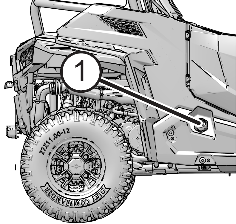
Engine Control Module
|
|
Accelerator Position 2
|
Voltage Above Normal, Or Shorted To High Source
|
29
|
3
|
|
Voltage Below Normal, Or Shorted To Low Source
|
4
|
|
Throttle Position Sensor 1
|
Voltage Above Normal, Or Shorted To High Source
|
51
|
3
|
|
Voltage Below Normal, Or Shorted To Low Source
|
4
|
|
Vehicle Speed Sensor
|
Data Erratic, Intermittent Or Incorrect
|
84
|
2
|
|
Accelerator Position 1
|
Voltage Above Normal, Or Shorted To High Source
|
91
|
3
|
|
Voltage Below Normal, Or Shorted To Low Source
|
4
|
|
Voltage Above Normal, Or Shorted To High Source
|
3
|
|
Voltage Below Normal, Or Shorted To Low Source
|
4
|
|
Manifold Absolute Pressure Sensor
|
Voltage Above Normal, Or Shorted To High Source
|
102
|
3
|
|
Voltage Below Normal, Or Shorted To Low Source
|
4
|
|
Intake Air Temperature Sensor
|
Data Valid But Above Normal Operational Range - Most Severe
Level
|
105
|
0
|
|
Voltage Above Normal, Or Shorted To High Source
|
3
|
|
Voltage Below Normal, Or Shorted To Low Source
|
4
|
|
Barometric Pressure Sensor
|
Voltage Above Normal, Or Shorted To High Source
|
108
|
3
|
|
Voltage Below Normal, Or Shorted To Low Source
|
4
|
|
Engine Temperature Sensor
|
Data Valid But Above Normal Operational Range - Most Severe
Level
|
110
|
0
|
|
Data Erratic, Intermittent Or Incorrect
|
2
|
|
Voltage Above Normal, Or Shorted To High Source
|
3
|
|
Voltage Below Normal, Or Shorted To Low Source
|
4
|
|
Abnormal Rate Of Change
|
10
|
|
Data Valid But Above Normal Operating Range - Moderately
Severe Level
|
16
|
|
Fuel Rail Pressure Sensor
|
Data Erratic, Intermittent Or Incorrect
|
157
|
2
|
|
Voltage Above Normal, Or Shorted To High Source
|
3
|
|
Voltage Below Normal, Or Shorted To Low Source
|
4
|
|
Data Valid But Above Normal Operating Range - Least Severe
Level
|
15
|
|
Data Valid But Below Normal Operating Range - Least Severe
Level
|
17
|
|
Data Valid But Below Normal Operational Range - Most Severe
Level
|
1
|
|
Data Erratic, Intermittent Or Incorrect
|
2
|
|
Voltage Above Normal, Or Shorted To High Source
|
3
|
|
Voltage Below Normal, Or Shorted To Low Source
|
4
|
|
Data Valid But Below Normal Operating Range - Moderately
Severe Level
|
18
|
|
Engine Speed
|
Condition Exists
|
190
|
31
|
|
Gear Sensor Signal
|
Data Erratic, Intermittent Or Incorrect
|
523
|
2
|
|
Crankshaft Position Sensor
|
Data Erratic, Intermittent Or Incorrect
|
636
|
2
|
|
Injector 1 (Front) (MAG) (SDI Port Injector)
|
Voltage Above Normal, Or Shorted To High Source
|
651
|
3
|
|
Voltage Below Normal, Or Shorted To Low Source
|
4
|
|
Current Below Normal Or Open Circuit
|
5
|
|
Injector 2 (Rear) (PTO) (SDI Port Injector)
|
Voltage Above Normal, Or Shorted To High Source
|
652
|
3
|
|
Voltage Below Normal, Or Shorted To Low Source
|
4
|
|
Current Below Normal Or Open Circuit
|
5
|
|
Starter Solenoid Driver Circuit
|
Voltage Above Normal, Or Shorted To High Source
|
677
|
3
|
|
Voltage Below Normal, Or Shorted To Low Source
|
4
|
|
Current Below Normal Or Open Circuit
|
5
|
|
Knock Sensor 1
|
Data Valid But Below Normal Operational Range - Most Severe
Level
|
731
|
1
|
|
Fan Relay Driver Circuit
|
Voltage Above Normal, Or Shorted To High Source
|
1071
|
3
|
|
Voltage Below Normal, Or Shorted To Low Source
|
4
|
|
Current Below Normal Or Open Circuit
|
5
|
|
Boost Pressure Sensor
|
Data Valid But Above Normal Operational Range - Most Severe
Level
|
1127
|
0
|
|
Data Erratic, Intermittent Or Incorrect
|
2
|
|
Voltage Above Normal, Or Shorted To High Source
|
3
|
|
Voltage Below Normal, Or Shorted To Low Source
|
4
|
|
Condition Exists
|
31
|
|
Ignition Coil Primary Driver 1 (Front) (MAG)
|
Voltage Above Normal, Or Shorted To High Source
|
1268
|
3
|
|
Ignition Coil Primary Driver 2 (Rear) (PTO)
|
Voltage Above Normal, Or Shorted To High Source
|
1269
|
3
|
|
PWM Fuel Pump
|
Voltage Above Normal, Or Shorted To High Source
|
1347
|
3
|
|
Voltage Below Normal, Or Shorted To Low Source
|
4
|
|
Current Below Normal Or Open Circuit
|
5
|
|
Fuel Pump Module Errors
|
Abnormal Frequency Or Pulse Width Or Period
|
|
8
|
|
|
Voltage Below Normal, Or Shorted To Low Source
|
|
4
|
|
Oxygen Sensor Bank 1 Sensor 1
|
Data Erratic, Intermittent Or Incorrect
|
3056
|
2
|
|
Voltage Above Normal, Or Shorted To High Source
|
3
|
|
Voltage Below Normal, Or Shorted To Low Source
|
4
|
|
Bad Intelligent Device Or Component
|
12
|
|
ECU Output Supply Voltage 1
|
Voltage Above Normal, Or Shorted To High Source
|
3597
|
3
|
|
Voltage Below Normal, Or Shorted To Low Source
|
4
|
|
ECU Output Supply Voltage 2
|
Voltage Above Normal, Or Shorted To High Source
|
3598
|
3
|
|
Voltage Below Normal, Or Shorted To Low Source
|
4
|
|
ECU Output Supply Voltage 3
|
Voltage Above Normal, Or Shorted To High Source
|
3599
|
3
|
|
Voltage Below Normal, Or Shorted To Low Source
|
4
|
|
Cylinder Misfire
|
Mechanical System Not Responding Or Out Of Adjustment
|
65590
|
7
|
|
Cylinder 1 Misfire
|
Mechanical System Not Responding Or Out Of Adjustment
|
65591
|
7
|
|
Cylinder 2 Misfire
|
Mechanical System Not Responding Or Out Of Adjustment
|
65592
|
7
|
|
ETC Accelerator Position Sensor Outputs 1 & 2 Correlation
|
Data Erratic, Intermittent Or Incorrect
|
65613
|
2
|
|
Fuel Pump Controller
|
Abnormal Frequency Or Pulse Width Or Period
|
66028
|
8
|
|
Bad Intelligent Device Or Component
|
12
|
|
Throttle Position Sensor 2
|
Voltage Above Normal, Or Shorted To High Source
|
520198
|
3
|
|
Voltage Below Normal, Or Shorted To Low Source
|
4
|
|
Canister Purge Valve
|
Voltage Above Normal, Or Shorted To High Source
|
520202
|
3
|
|
Voltage Below Normal, Or Shorted To Low Source
|
4
|
|
Current Below Normal Or Open Circuit
|
5
|
|
All Wheel Drive Control Circuit
|
Voltage Above Normal, Or Shorted To High Source
|
520207
|
3
|
|
Voltage Below Normal, Or Shorted To Low Source
|
4
|
|
Current Below Normal Or Open Circuit
|
5
|
|
Chassis Relay
|
Voltage Above Normal, Or Shorted To High Source
|
520208
|
3
|
|
Voltage Below Normal, Or Shorted To Low Source
|
4
|
|
Current Below Normal Or Open Circuit
|
5
|
|
Oxygen Sensor Heater 1
|
Data Erratic, Intermittent Or Incorrect
|
520209
|
2
|
|
Voltage Above Normal, Or Shorted To High Source
|
3
|
|
Voltage Below Normal, Or Shorted To Low Source
|
4
|
|
Current Below Normal Or Open Circuit
|
5
|
|
Accelerator Position/Brake Position Interaction
|
Condition Exists
|
520275
|
31
|
|
Throttle Position Sensor (1 or 2 Indeterminable)
|
Data Erratic, Intermittent Or Incorrect
|
520276
|
2
|
|
Bad Intelligent Device Or Component
|
12
|
|
Throttle Body Control - Power Stage
|
Data Erratic, Intermittent Or Incorrect
|
520277
|
2
|
|
Voltage Above Normal, Or Shorted To High Source
|
3
|
|
Voltage Below Normal, Or Shorted To Low Source
|
4
|
|
Abnormal Frequency Or Pulse Width Or Period
|
8
|
|
Throttle Body Control - Adaption Aborted
|
Condition Exists
|
520279
|
31
|
|
Throttle Body Control - Limp Home Position Check Failed
|
Condition Exists
|
520280
|
31
|
|
Throttle Body Control - Mechanical Stop Adaptation Failure
|
Condition Exists
|
520281
|
31
|
|
Throttle Body Control - Repeated Adaptation Failed
|
Condition Exists
|
520282
|
31
|
|
Throttle Body Control
|
Voltage Above Normal, Or Shorted To High Source
|
520283
|
3
|
|
Voltage Below Normal, Or Shorted To Low Source
|
4
|
|
Throttle Body Control - Position Deviation Fault
|
Condition Exists
|
520284
|
31
|
|
Brake Switch (1 or 2 Indeterminable)
|
Data Erratic, Intermittent Or Incorrect
|
520285
|
2
|
|
ECU Monitoring Error
|
Condition Exists
|
520286
|
31
|
|
ECU Monitoring Error (Level 3)
|
Condition Exists
|
520287
|
31
|
|
ECU Monitoring of Injection Cut Off (Level 1)
|
Condition Exists
|
520288
|
31
|
|
ECU Monitoring of Injection Cut Off (Level 2)
|
Condition Exists
|
520289
|
31
|
|
Throttle Body Control - Requested Throttle Angle Not Plausible
|
Condition Exists
|
520305
|
31
|
|
ECU ADC Fault - No Load
|
Condition Exists
|
520306
|
31
|
|
ECU ADC Fault - Voltage
|
Condition Exists
|
520307
|
31
|
|
Accelerator Sensor Sync Fault - Sensor Diff Exceeds Limit
|
Condition Exists
|
520308
|
31
|
|
ECU Fault - ICO
|
Condition Exists
|
520309
|
31
|
|
ECU Fault - Hardware Disruption
|
Condition Exists
|
520311
|
31
|
|
Knock Sensor Positive Line
|
Voltage Above Normal, Or Shorted To High Source
|
520331
|
3
|
|
Voltage Below Normal, Or Shorted To Low Source
|
4
|
|
Knock Sensor Negative Line
|
Voltage Above Normal, Or Shorted To High Source
|
520332
|
3
|
|
Voltage Below Normal, Or Shorted To Low Source
|
4
|
|
ECU Monitoring (Pedal Map Mismatch)
|
Condition Exists
|
520336
|
31
|
|
Wastegate Solenoid Driver
|
Voltage Above Normal, Or Shorted To High Source
|
520341
|
3
|
|
Voltage Below Normal, Or Shorted To Low Source
|
4
|
|
Current Below Normal Or Open Circuit
|
5
|
|
Adaptive Fuel Correction Bank 1
|
Data Valid But Above Normal Operating Range - Least Severe
Level
|
520344
|
15
|
|
Data Valid But Below Normal Operating Range - Least Severe
Level
|
17
|
|
Intercooler Pump Driver Circuit
|
Voltage Above Normal, Or Shorted To High Source
|
520496
|
3
|
|
Voltage Below Normal, Or Shorted To Low Source
|
4
|
|
Current Below Normal Or Open Circuit
|
5
|
|
Wideband Oxygen Sensor Bank 1 Sensor 1 Pumping Current Trim
|
Current Below Normal Or Open Circuit
|
520612
|
5
|
|
Wideband Oxygen Sensor Bank 1 Sensor 1 Positive Current
Control
|
Current Below Normal Or Open Circuit
|
520613
|
5
|
|
Wideband Oxygen Sensor Bank 1 Sensor 1 Negative Current
Control
|
Current Below Normal Or Open Circuit
|
520614
|
5
|
|
Wideband Oxygen Sensor Bank 1 Sensor 1 Reference Voltage
|
Current Below Normal Or Open Circuit
|
520615
|
5
|
|
Wideband Chip
|
Bad Intelligent Device Or Component
|
520679
|
12
|
|
Start Switch
|
Data Erratic, Intermittent Or Incorrect
|
521083
|
2
|
|
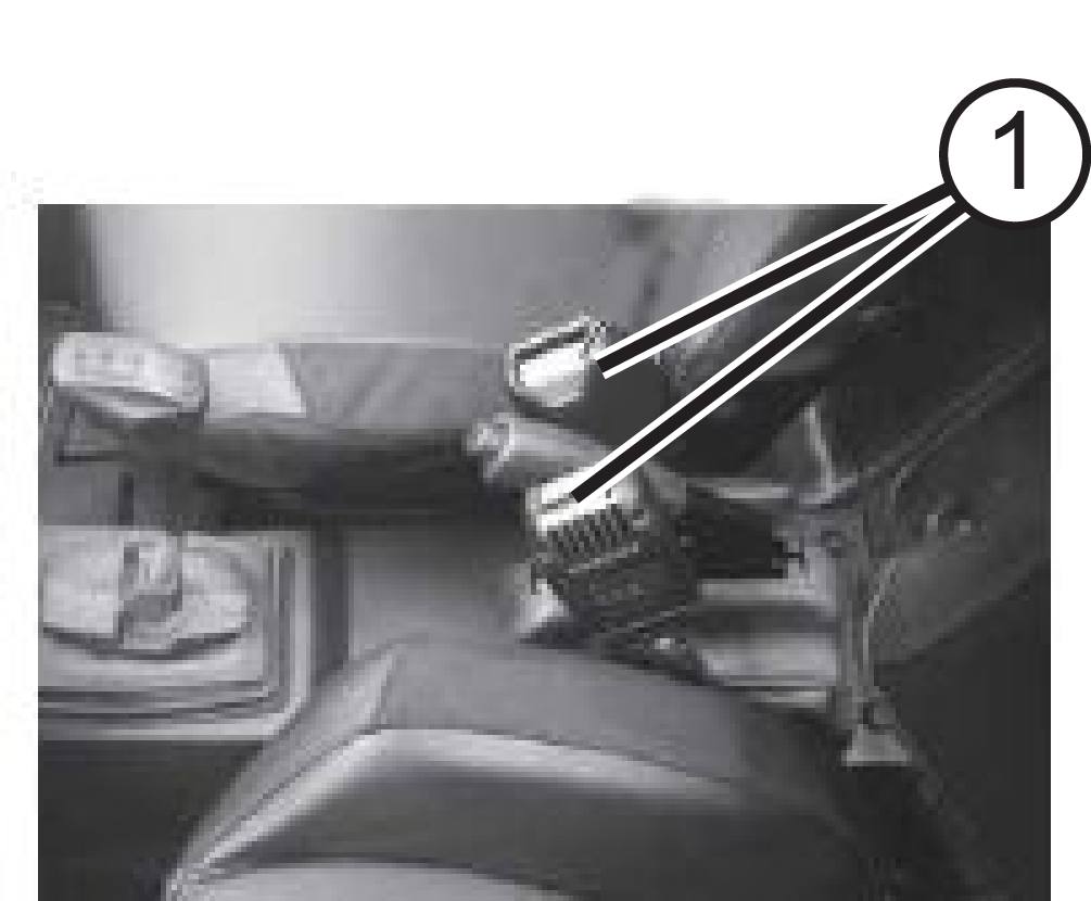
EPAS Module
|
|
Steering Over Current Shut Down
|
Current Above Normal Or Grounded Circuit
|
520221
|
6
|
|
Steering Excessive Current Error
|
Current Above Normal Or Grounded Circuit
|
520222
|
6
|
|
Steering Torque Partial Failure
|
Condition Exists
|
520223
|
31
|
|
Steering Torque Full Failure
|
Condition Exists
|
520224
|
31
|
|
EPAS Inverter Temperature
|
Data Valid But Above Normal Operational Range - Most Severe
|
520225
|
0
|
|
Data Valid But Above Normal Operating Range - Severe
|
16
|
|
EPAS
Communications Receive Data Error
|
Data Erratic, Intermittent Or Incorrect
|
520226
|
2
|
|
Condition Exists
|
520226
|
31
|
|
Position Encoder Error
|
Root Cause Not Known
|
520228
|
11
|
|
Bad Intelligent Device Or Component
|
520228
|
12
|
|
Condition Exists
|
520228
|
31
|
|
EPAS Software Error
|
Bad Intelligent Device Or Component
|
520229
|
12
|
|
Condition Exists
|
520229
|
31
|
|
EPAS Power Save Condition
|
Condition Exists
|
520231
|
31
|
|
EPS SEPIC Voltage Error
|
Voltage Above Normal, Or Shorted To High Source
|
524086
|
3
|
|
Voltage Below Normal, Or Shorted To Low Source
|
524086
|
4
|
|
Calibration CRC
|
Checksum/CRC Error
|
630
|
13
|
|
Steering Torque Full Failure
|
Torque Sensor Out of Range
|
520223
|
31
|
|
Torque Sensor Linearity Error
|
520224
|
31
|
|
EPS CAN Communications Receive Error
|
No RX Message for {{cal parameter}} seconds
|
520226
|
2
|
|
Vehicle Speed
|
Vehicle Speed Too High
|
84
|
0
|
|
Vehicle Speed Implausible
|
10
|
|
Received Vehicle Speed has Errors
|
19
|
|
Engine Speed
|
Engine Speed Too High
|
190
|
0
|
|
Received Engine Speed has Errors
|
190
|
19
|
|
Battery Voltage
|
Too High
|
168
|
3
|
|
Battery Voltage
|
Too Low
|
168
|
4
|
|
Position Encoder Error
|
Loss of SPI Communication
|
520228
|
12
|
|
Encoder Variance Error
|
31
|
|
EPS Software Error
|
Manufacturing CRC Error
|
520229
|
12
|
|
Boot Count Error
|
31
|
|
ICS Communication
|
Loss of CAN between EPS and Instrument Cluster
|
520230
|
31
|
|
EPAS Power Save
|
5 minute time out
|
520231
|
31
|
|
ECU Memory
|
EEPROM Communication Error
|
628
|
12
|
|
Application CRC Error
|
13
|
|
VGD Low
|
VGD Low
|
524086
|
4
|
|
Absolute Position Sensor
|
Absolute Position Sensor Out of Range
|
1807
|
31
|
|
Absolute Position Sensor Not Calibrated
|
1807
|
13
|
|
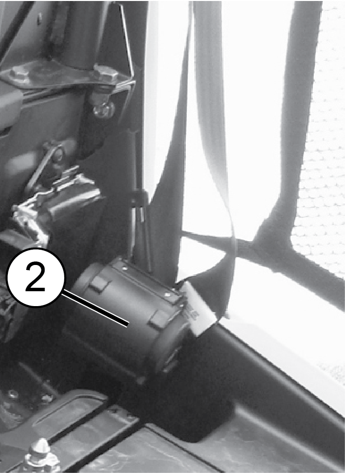
Suspension Control
Module
|
|
Vehicle Speed Sensor
|
Data Drifted High
|
84
|
20
|
|
Data Drifted Low
|
21
|
|
Transmission Requested Range Data
|
Data Erratic, Intermittent Or Incorrect
|
162
|
2
|
|
Suspension Mode Switch Input
|
Data Erratic, Intermittent Or Incorrect
|
516098
|
2
|
|
Voltage Above Normal, Or Shorted To High Source
|
3
|
|
Voltage Below Normal, Or Shorted To Low Source
|
4
|
|
Valve Driver Front Left
|
Voltage Above Normal, Or Shorted To High Source
|
516106
|
3
|
|
Voltage Below Normal, Or Shorted To Low Source
|
4
|
|
Valve Driver Front Right
|
Voltage Above Normal, Or Shorted To High Source
|
516107
|
3
|
|
Voltage Below Normal, Or Shorted To Low Source
|
4
|
|
Valve Driver Rear Left
|
Voltage Above Normal, Or Shorted To High Source
|
516108
|
3
|
|
Voltage Below Normal, Or Shorted To Low Source
|
4
|
|
Valve Driver Rear Right
|
Voltage Above Normal, Or Shorted To High Source
|
516109
|
3
|
|
Voltage Below Normal, Or Shorted To Low Source
|
4
|
|
Shock Valve Power Supply Relay Driver
|
Voltage Above Normal, Or Shorted To High Source
|
516110
|
3
|
|
Voltage Below Normal, Or Shorted To Low Source
|
4
|
|
Absolute Shock Current Error - Front Left
|
Root Cause Not Known
|
516111
|
11
|
|
Absolute Shock Current Error - Front Right
|
Root Cause Not Known
|
516112
|
11
|
|
Absolute Shock Current Error - Rear Left
|
Root Cause Not Known
|
516113
|
11
|
|
Absolute Shock Current Error - Rear Right
|
Root Cause Not Known
|
516114
|
11
|
|
Internal Inertial Measurement Unit
|
Bad Intelligent Device Or Component
|
516115
|
12
|
|
Data Valid But Above Normal Operating Range - Least Severe
Level
|
15
|
|
Data Valid But Below Normal Operating Range - Least Severe
Level
|
|
17
|
|
CAN Message PGN 65382
|
Abnormal Update Rate
|
516116
|
9
|
|
CAN Message PGN 65396
|
Abnormal Update Rate
|
516117
|
9
|
|
CAN Message PGN 65314
|
Abnormal Update Rate
|
516118
|
9
|
|
SW Version & HW Version Mismatch
|
Data Erratic, Intermittent Or Incorrect
|
516119
|
2
|
|
CAN Message PGN 65265
|
Abnormal Update Rate
|
516120
|
9
|
|
CAN Message PGN 61445
|
Abnormal Update Rate
|
516121
|
9
|
|
Steering Angle Adoption Offset
|
Data Valid But Above Normal Operating Range - Least Severe
Level
|
516122
|
15
|
|
Vehicle Speed Data
|
Data Erratic, Intermittent Or Incorrect
|
516123
|
2
|
|
Data Drifted High
|
20
|
|
Suspension Control Module
|
Bad Intelligent Device Or Component
|
516124
|
12
|
|
CAN 1
|
Root Cause Not Known
|
516125
|
11
|
|
System Voltage
|
Data Valid But Above Normal Operational Range - Most Severe
Level
|
516126
|
0
|
|
Data Valid But Below Normal Operational Range - Most Severe
Level
|
1
|
|
Voltage Above Normal, Or Shorted To High Source
|
3
|
|
Voltage Below Normal, Or Shorted To Low Source
|
4
|
|
Data Valid But Above Normal Operating Range - Moderately
Severe Level
|
|
16
|
|
Data Valid But Below Normal Operating Range - Moderately
Severe Level
|
18
|
|
Raw Brake Switch Status
|
Data Erratic, Intermittent Or Incorrect
|
520572
|
2
|
|
Normalized Accelerator Pedal Position
|
Data Erratic, Intermittent Or Incorrect
|
520574
|
2
|
|
Engine Speed Data
|
Data Erratic, Intermittent Or Incorrect
|
524000
|
2
|
|
Steering Angle Input
|
Data Erratic, Intermittent Or Incorrect
|
524114
|
2
|