i 2024 PRO XD Diesel Owner’s Manual

|
| 2024 Owner’s Manual |
| Pro XD Full-Size Diesel Pro XD Full Size Diesel Crew |
The Owner's Manual for this vehicle contains warnings, instructions and other information you must read and fully understand before safely riding or performing maintenance on this vehicle. Always follow the warnings and instructions in Owner's Manual.
Click the link above for the Table Of Contents, or download a full PDF of the Owner Manual in the Owner Support area of Polaris.com.
|
|
| 2024 Owner’s Manual |
| Pro XD Full-Size Diesel Pro XD Full Size Diesel Crew |
Unless noted, trademarks are the property of Polaris Industries, Inc.
Loctite® is a registered trademark of Henkel Corporation. NYOGEL® is a registered trademark of Nye Lubricants, Inc. Tread LightlySM is a service trademark of the United States Department of Agriculture. QR Code® is a registered trademark of DENSO WAVE INCORPORATED. WD-40® is registered to WD-40 Manufacturing Company. Bluetooth® is a registered trademark of Bluetooth Sig, Inc. Kubota® is a registered trademark of Kubota Corporation Japan.
Copyright 2023 Polaris Industries Inc. All information contained within this publication is based on the latest product information at the time of publication. Due to constant improvements in the design and quality of production components, some minor discrepancies may result between the actual vehicle and the information presented in this publication. Depictions and/or procedures in this publication are intended for reference use only. No liability can be accepted for omissions or inaccuracies. Any reprinting or reuse of the depictions and/or procedures contained within, whether whole or in part, is expressly prohibited.
The original instructions for this vehicle are in English. Other languages are provided as translations of the original instructions.
Printed in U.S.A.

Thank you for purchasing a POLARIS vehicle, and welcome to our world-wide family of POLARIS enthusiasts. Be sure to visit us online at www.polaris.com for the latest news, new product introductions, upcoming events, career opportunities and more.
Here at POLARIS we proudly produce an exciting line of utility and recreational products. We believe POLARIS sets a standard of excellence for all utility and recreational vehicles manufactured in the world today. Many years of experience have gone into the engineering, design, and development of your POLARIS vehicle.
For safe and enjoyable operation of your vehicle, be sure to follow the instructions and recommendations in this owner’s manual. Your manual contains instructions for minor maintenance, but information about major repairs is outlined in the POLARIS Service Manual and can be performed by a factory certified Master Service Dealer (MSD) technician.
Your POLARIS dealer knows your vehicle best and is interested in your total satisfaction. Your POLARIS dealership can perform all of your service needs during and after the warranty period.
For the most up-to-date owner’s manual visit
https://www.polaris.com/en-us/owners-manuals
.
Failure to follow the warnings contained in this manual can result in severe injury or death.
This vehicle is not a toy and can be hazardous to operate. This vehicle handles differently than other vehicles. A collision or rollover can occur quickly, even during routine maneuvers, if you fail to take proper precautions.
Read this owner’s manual. Understand all safety warnings, precautions and operating procedures before operating the vehicle. Keep this manual with the vehicle at all times.
This vehicle is an ADULT VEHICLE ONLY. You MUST be at least 16 years of age and have a valid driver’s license to operate this vehicle.
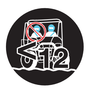
No person under the age of 12 may ride as a passenger in this vehicle.
Never permit a guest to operate this vehicle unless the guest has read this manual and all product labels.
Always keep hands, feet, and all other body parts inside the vehicle at all times.
Always wear the proper clothing when operating or riding in this vehicle. All riders should wear substantial footwear, long pants, and a close-fitting shirt. A hard hat or helmet and approved eye protection are recommended when appropriate for riding or working conditions.
Never operate this vehicle under the influence of drugs or alcohol, as these conditions impair judgement and the operator’s ability to react.
The following signal words and symbols appear throughout this manual and on your vehicle. Your safety is involved when these words and symbols are used. Become familiar with their meanings before reading the manual.
DANGER indicates a hazardous situation which, if not avoided, WILL result in death or serious injury.
WARNING indicates a hazardous situation which, if not avoided, COULD result in death or serious injury.
CAUTION indicates a hazardous situation which, if not avoided, COULD result in minor to moderate injury.
NOTICE provides key information by clarifying instructions.
IMPORTANT provides key reminders during disassembly, assembly, and inspection of components.
The Prohibition Safety Sign indicates an action NOT to take in order to avoid a hazard.

The Mandatory Action Sign indicates an action that NEEDS to be taken to avoid a hazard.

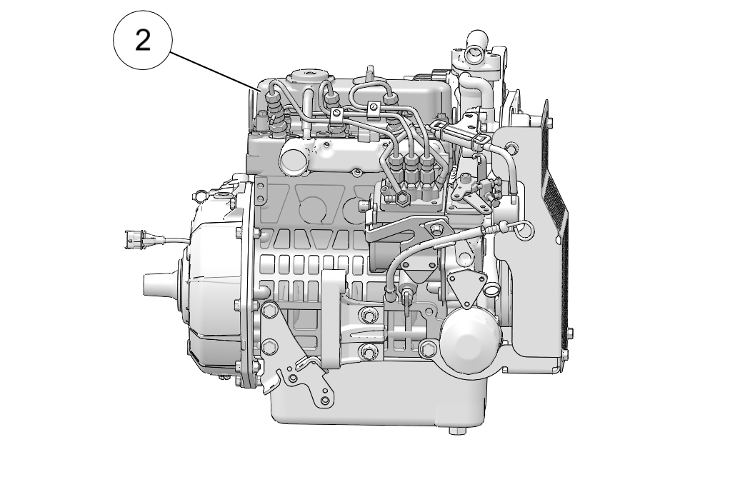
Record your vehicle's identification numbers in the spaces provided. The engine serial number is located on the side of the engine, below the injection pump.
All keys have the number 4083. Remove the spare key and store it in a safe place. Additional pre-cut keys for your vehicle can be ordered.
| Vehicle Model Number | |
| Vehicle Identification Number (VIN) 1 | |
| Engine Serial Number 2 | |
| Key Number | 4083 |
Always wear the proper clothing when operating or riding in this vehicle. All riders should wear substantial footwear, long pants and a close-fitting shirt. A hard hat or helmet and approved eye protection are recommended when appropriate for working or riding conditions. POLARIS recommends wearing approved eye protection bearing markings such as VESC 8, V-8, Z87.1 or CE. Never operate or ride in this vehicle while barefoot or while wearing sandals or tennis shoes.
Workplace safety regulations may require the use of safety glasses, safety shoes and a hard hat or helmet. Familiarize yourself with local requirements, be prepared for operating conditions and wear the appropriate safety gear.
Under certain operating conditions, heat generated by the engine and exhaust system can elevate temperatures in the driver and passenger cab area. The condition occurs most frequently when a vehicle is being operated in high ambient temperatures at low speeds and/or high load conditions for an extended period of time. The use of certain windshield, roof and/or cab systems may contribute to this condition by restricting airflow. Any discomfort due to heat buildup in this area can be minimized by wearing proper riding apparel and by varying speeds to increase airflow.
Warning labels have been placed on the vehicle for your protection. Read and follow the instructions of the labels on the vehicle carefully. If any of the labels depicted in this manual differ from the labels on your vehicle, always read and follow the instructions of the labels on the vehicle.
If an informational or graphic label becomes illegible or comes off, contact your POLARIS dealer to purchase a replacement. Replacement safety labels are provided by POLARIS at no charge. The part number is printed on the label.
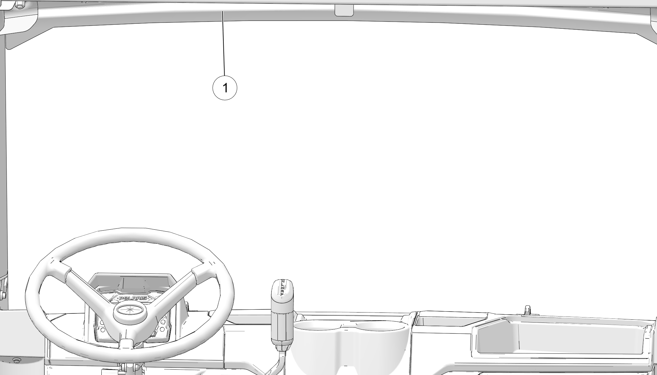
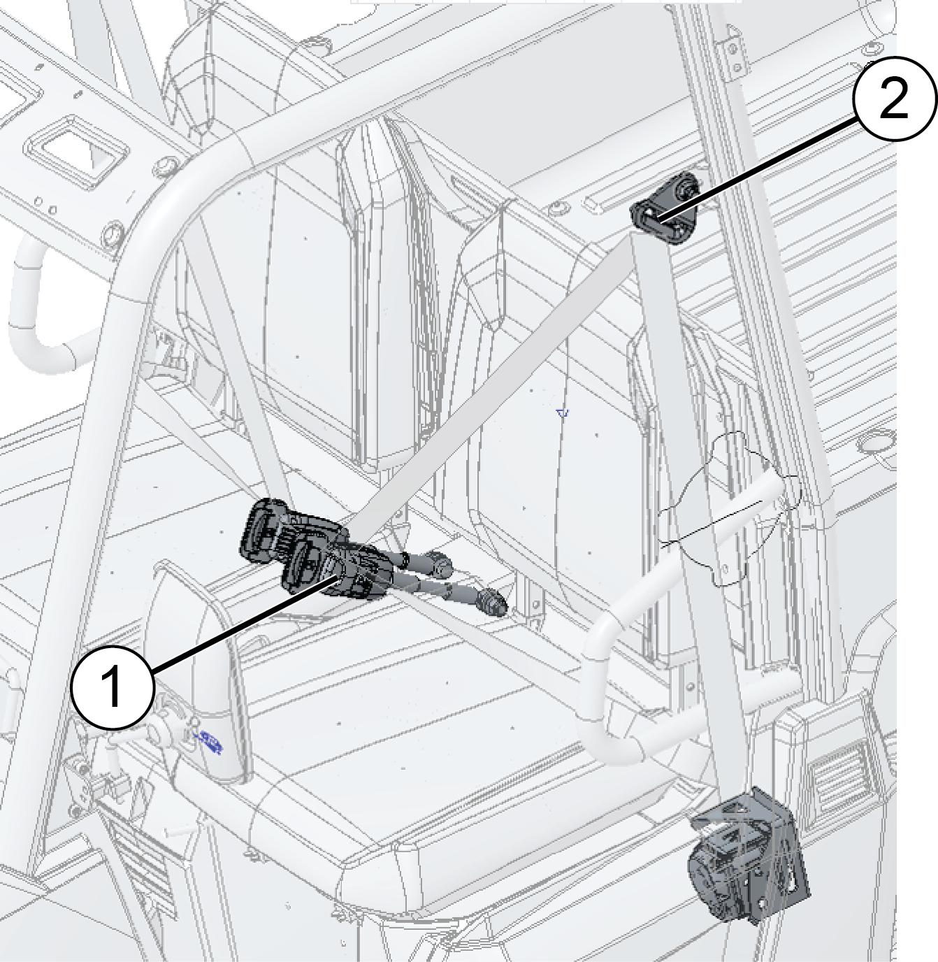
The seat belt/drive responsibly warning label , the proper use warning label, and the payload warning are located on the front ROPS, above the driver’s head 1.
WARNING
Part Number: 7300410
IMPROPER VEHICLE USE CAN RESULT IN SERIOUS INJURY OR DEATH
NEVER OPERATE:
At speeds too fast for your skills or the conditions.
After or while using Alcohol or Drugs.
Across slopes (Avoid side hilling).
On public roads. This vehicle is for off-highway use only. Driving on public roads could be a violation of law and may be hazardous.
With more passengers than described in the Operation & Maintenance Manual, with children under the age of 12, and passengers who cannot comfortably reach the floor and hand holds with back against the seat.
With unapproved accessories - they may seriously affect stability.
LOCATE AND READ OPERATION & MAINTENANCE MANUAL. FOLLOW ALL INSTRUCTIONS AND WARNINGS.
ALWAYS:
Wear head protection - such as a hard hat or helmet - as appropriate for conditions and usage. Consult manual for more information.
Wear your seatbelt. Vehicle rollover could cause serious injury or death.
Wear eye protection and keep hands and feet in vehicle at all times.
Reduce speed and use extra caution when carrying passengers.
Avoid sharp turns or turns while applying heavy throttle.
Operate slowly in reverse - avoid sharp turns or sudden braking.
Make sure passengers read and understand all warning labels.
Watch for branches or other hazards that could enter vehicle.
Use caution while operating vehicle on private paved surfaces. Pavement can alter handling and may cause loss of control.
Be Sure Riders Pay Attention and Plan Ahead
If you think or feel the vehicle may tip or roll, reduce your risk to injury:
Keep a firm grip on the steering wheel or handholds and brace yourself.
Do not put any part of your body outside of the vehicle for any reason.
Rollovers have caused severe injuries and death, even on flat, open areas.
WARNING
Part Number: 7300098
Require Proper Use of Your Vehicle
Do your
part to prevent injuries:
Do not allow careless or reckless driving.
Make sure operators are 16 or older with a valid driver’s license.
Do not let people drive or ride after using alcohol or drugs.
Do not allow operation on public roads (unless designated for off-highway vehicle access) - collisions with cars and trucks can occur.
Do not exceed seating capacity: 2 occupants.
WARNING
Part Number: 7300099
Require Proper Use of Your Vehicle
Do your
part to prevent injuries:
Do not allow careless or reckless driving.
Make sure operators are 16 or older with a valid driver’s license.
Do not let people drive or ride after using alcohol or drugs.
Do not allow operation on public roads (unless designated for off-highway vehicle access) - collisions with cars and trucks can occur.
Do not exceed seating capacity: 4 occupants.
WARNING
Part Number: 7300640
| WARNING | ||
|---|---|---|
| Model | Never Exceed | If Total Payload Exceeds |
| Full-Size Diesel | 25 mph (40 kph) | 860 lbs. (376 kg) |
| Full-Size Diesel Crew | 25 mph (40 kph) | 860 lbs. (376 kg) |
| Full-Size Gas | 25 mph (40 kph) | 1250 lbs. (567 kg) |
| Full-Size Gas Crew | 25 mph (40 kph) | 1250 lbs. (567 kg) |
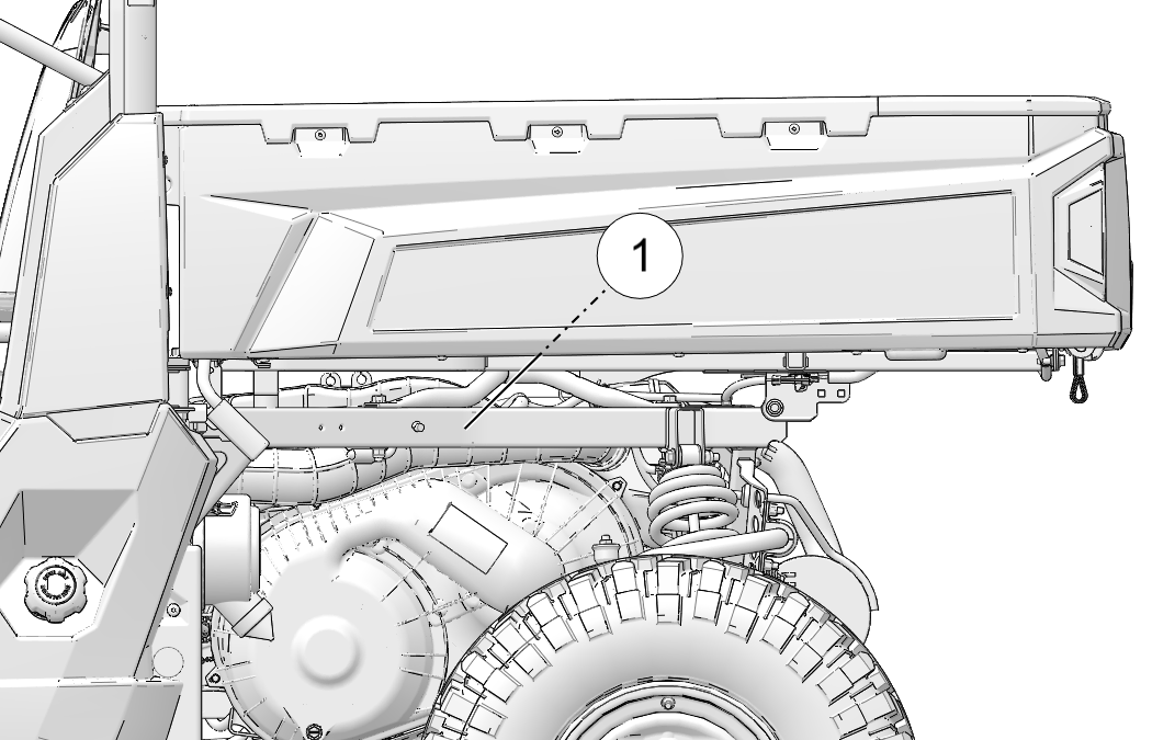
The fuel transport warning label 1 is located in the cargo box.
WARNING
Part Number: 7186122
NEVER carry fuel or other flammable liquids on this vehicle.
Failure to follow this instruction could lead to serious burn injuries or death.
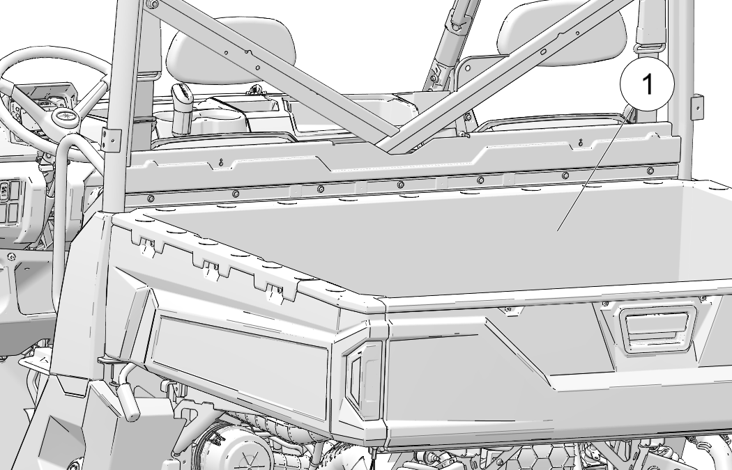
The load/passenger/tire pressure warning label is located next to the fuel transport warning label in the cargo box.
WARNING
Part Number: 7300637
FALLING OFF CARGO BOX CAN CAUSE SERIOUS INJURY OR DEATH
Never carry riders in cargo box.
OVERLOADING OR IMPROPER TIRE PRESSURE CAN CAUSE TIPPING OR LOSS OF CONTROL RESULTING IN SERIOUS INJURY OR DEATH
Never exceed load capacities.
Reduce speed and allow greater distance for braking when carrying cargo.
Carrying tall, off-center, or unsecured loads will increase your risk of losing control. Center and secure loads as low as possible in box.
Reduce speed and cargo on rough or hilly terrain.
Check for proper tire pressures.
|
MODEL NUMBER |
Full-Size Diesel |
Full-Size Diesel Crew |
Full-Size Gas |
Full-Size Gas Crew |
|---|---|---|---|---|
|
MAXIMUM CARGO BOX LOAD |
1250 lbs. (566 kg) |
1250 lbs. (566 kg) |
1250 lbs. (566 kg) |
1250 lbs. (566 kg) |
|
TIRE PRESSURE IN PSI (KPa) |
FRONT 24 (165) REAR 24 (165) |
FRONT 24 (165) REAR 24 (165) |
FRONT 5 (34) REAR 20 (138) |
FRONT 10 (69) REAR 20 (138) |
|
VEHICLE RATED CAPACITY
|
1900 lbs. (861 kg) |
2075 lbs. (941 kg) |
1900 lbs. (861 kg) |
2075 lbs. (941 kg) |
|
GVWR |
3600 lbs. 1633 kg |
4000 lbs. 1814 kg |
3600 lbs. 1633 kg |
4000 lbs. 1814 kg |
|
Read Operation & Maintenance Manual for more detailed loading information. |
||||
The clutch cover warning 1 is located on the clutch cover.
WARNING
Part Number: 7182350
Improper service or maintenance of this CVT system can result in vehicle damage, SEVERE INJURY or DEATH.
Always look for and remove debris inside and around clutch and vent system when replacing belt.
Read owner’s manual or see an authorized service dealer.
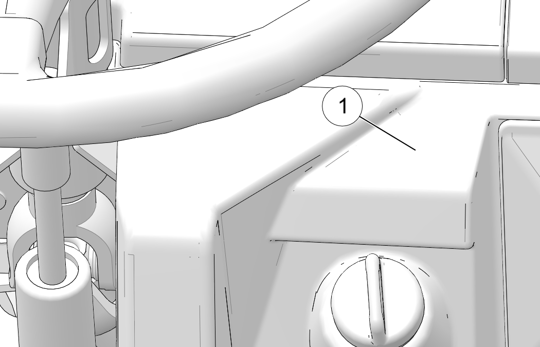
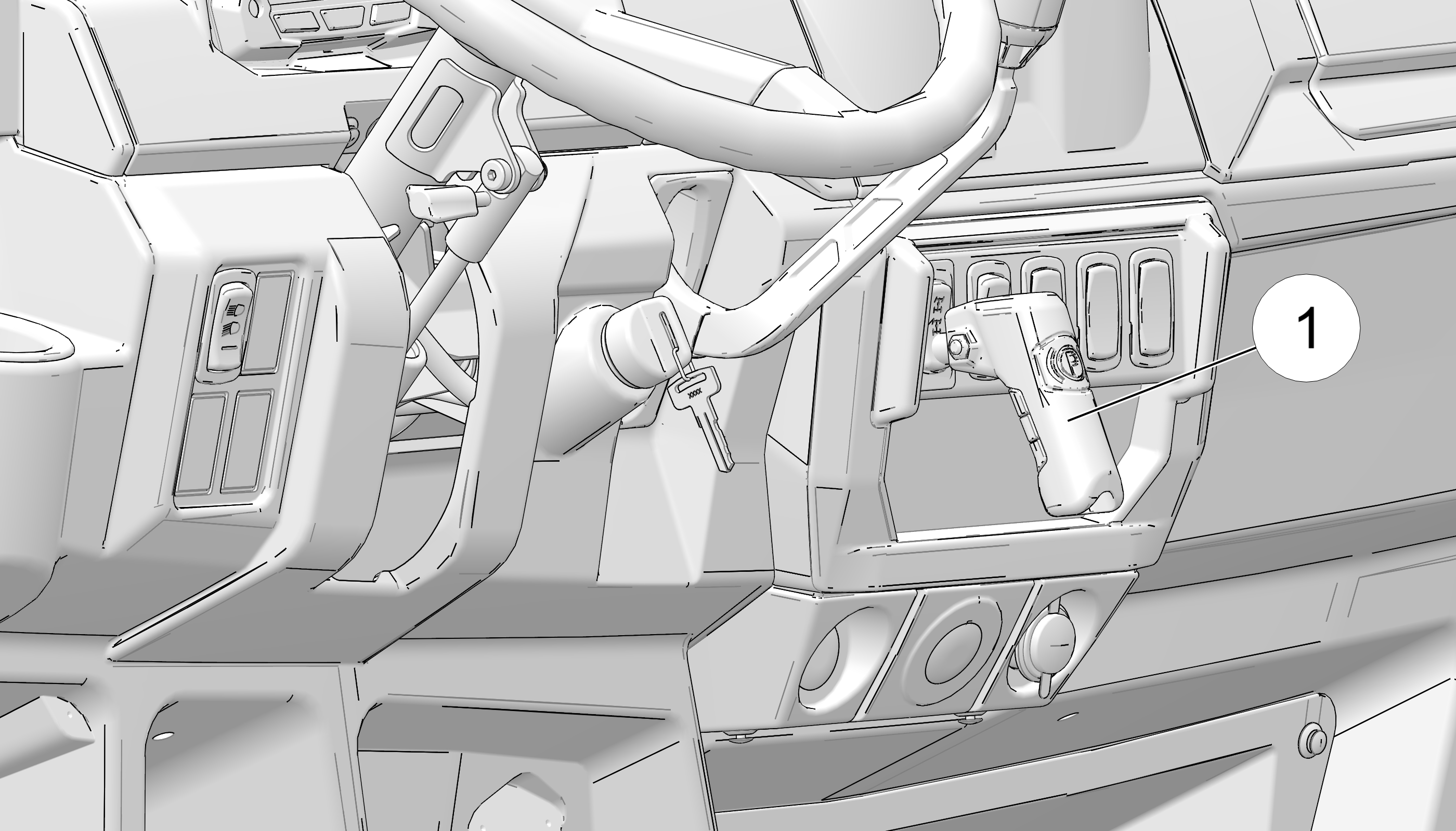
The shift caution 1 is located above the ignition switch.
CAUTION
Part Number: 7300087
To avoid transmission damage, shift only when vehicle is stationary and at idle. When vehicle is stopped, place gear selector in PARK.
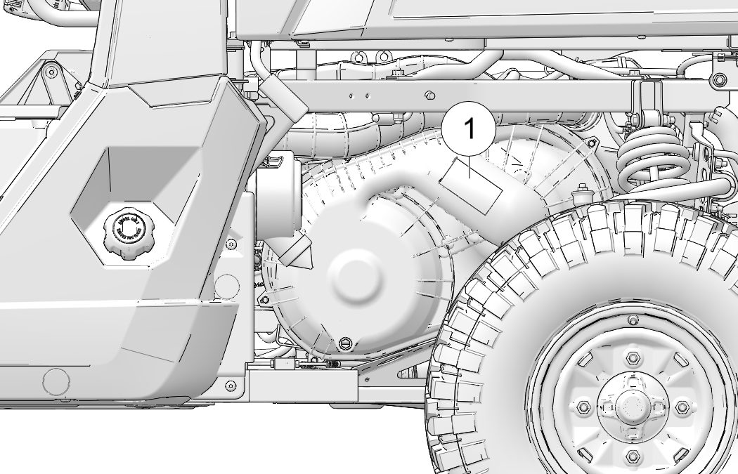
The pulley warning 1 is located on the rear frame.
WARNING
Part Number: 7182156
Moving parts present. Keep hands away from moving parts to prevent injury.
The trailer/hitch capacity label is located on the rear hitch bracket.
CAUTION
Part Number: 7300095
CAUTION:
HOT SURFACE. DO NOT TOUCH.
TRAILER MAX. WEIGHT: 2500 LBS. (1134 kg)
HITCH MAX. VERTICAL WEIGHT: 250 LBS. (114 kg)
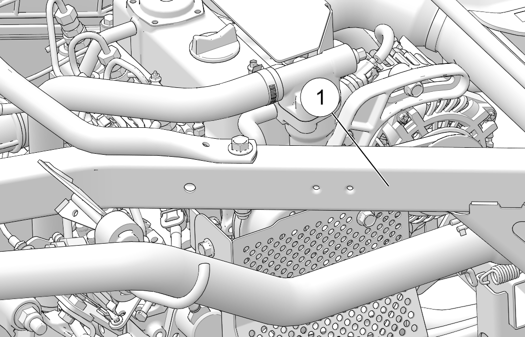
The Hot Surface caution label is located
on the vehicle frame near the exhaust.
CAUTION
HOT SURFACE. DO NOT TOUCH.
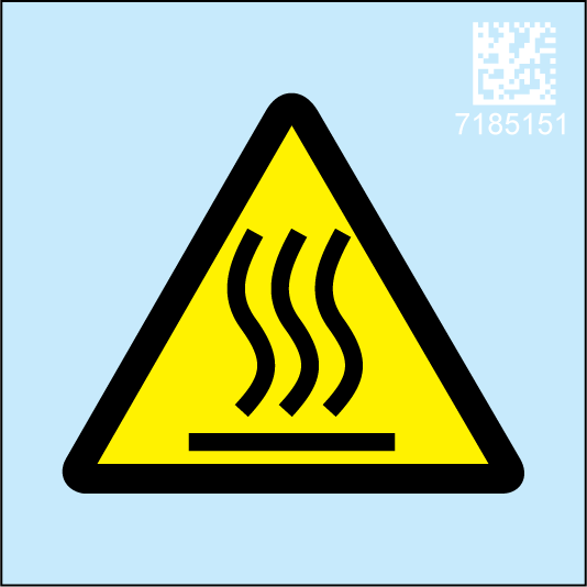
Part number: 7185151
Read this entire manual and all labels carefully. Follow the operating procedures described.
Never allow anyone under the age of 16 to operate this vehicle and never allow anyone without a valid driver's license to operate this vehicle.
Do not carry a passenger until you have at least two hours of driving experience with this vehicle.
No person under the age of 12 may ride as a passenger in this vehicle.
Always keep hands and feet inside the vehicle at all times. Always keep both hands on the steering wheel (driver) and both feet on the floorboards of the vehicle during operation.
Never permit a guest to operate this vehicle unless the guest has read this manual and all product labels.
Always make sure the seat belts are secured for operator and passenger before operating.
Never exceed the stated load capacity for this vehicle. Cargo should be properly distributed and securely attached. Reduce speed and follow the instructions in this manual for hauling cargo or pulling a trailer. Allow a greater distance for braking.
Always be sure there are no obstacles or people behind your vehicle when operating in reverse. When it's safe to proceed in reverse, move slowly. Avoid turning at sharp angles in reverse.
Always use the proper size and type of tires specified in this manual. Always maintain proper tire pressure as specified on safety labels.
Never modify this vehicle through improper installation or use of non-POLARIS-approved accessories.
Always set the park brake and remove the key when leaving the vehicle unattended.
Never consume alcohol or drugs before or while operating this vehicle.
Never operate at excessive speeds. Always operate at a speed that's appropriate for the traffic, the visibility and operating conditions, your skills and your passengers’ skills.
Always inspect the vehicle before each use to make sure it's in safe operating condition. Always follow the inspection procedures described in this manual.
Always travel slowly and use extra caution when operating on unfamiliar terrain. Be alert to changing terrain.
Always follow proper procedures for turning. Make turns slowly, especially when the ground is wet, greasy, bumpy or sloping. Never turn the steering wheel abruptly when driving at high speed.
Always have this vehicle checked by an authorized POLARIS dealer if it has been involved in an accident.
Always be alert for obstacles when operating this vehicle. Never attempt to operate over obstacles.
Never operate this vehicle on steep hills.
Never operate on excessively rough, slippery or loose terrain.
Always be careful of skidding or sliding. On slippery surfaces such as ice, travel slowly and exercise caution to reduce the chance of skidding or sliding out of control.
Always be sure there are no obstacles or people behind your vehicle when operating in reverse. When it's safe to proceed in reverse, move slowly. Avoid turning at sharp angles in reverse.
Always stop the engine before refueling. Remove flammable material containers from the box before filling them with fuel. Make sure the refueling area is well ventilated and free of any source of flame or sparks.
Failure to operate the vehicle properly can result in a collision, loss of control, accident or rollover, which may result in serious injury or death. Heed all safety warnings outlined in this section of the owner’s manual. See the OPERATION section of the owner’s manual for proper operating procedures.
Operating this vehicle without proper instruction increases the risk of an accident. The operator must understand how to operate the vehicle properly in different situations and on different types of terrain. All operators must read and understand the Owner's Manual and all warning and instruction labels before operating the vehicle.

|
This vehicle is an ADULT VEHICLE ONLY. NEVER operate this vehicle if you are under age 16 and NEVER operate without a valid driver’s license. Never operate with a passenger under the age of 12. All riders must be able to sit with backs against the seat, both feet flat on the floor and both hands on the steering wheel (if driving) or on a passenger hand hold (if equipped). |
|

|
|
Never consume alcohol or drugs before
or while operating this vehicle.
Operating
this vehicle after consuming alcohol or drugs could adversely affect
operator judgment, reaction time, balance and perception.

|
Riding in this vehicle without wearing the seat belt increases the risk of serious injury in the event of rollover, loss of control, other accident or sudden stop. Seat belts may reduce the severity of injury in these circumstances. All riders must wear seat belts at all times. |
|
Operating this vehicle with improper tires or with improper or uneven tire pressure could cause loss of control or accident. Always use the size and type of tires specified for your vehicle. Always maintain proper tire pressure as described in the owner's manual and on safety labels.
The weight of the cargo, operator, and passengers impacts vehicle operation and stability. For your safety and the safety of others, carefully consider how your vehicle is loaded and how to safely operate the vehicle. Follow the instructions in this manual for loading, tire pressure, gear selection and speed.
Do not exceed vehicle weight capacities. The vehicle’s maximum weight capacity is listed in the specifications section of this manual and on a label on the vehicle. When determining the weight you are adding to the vehicle, include the weight of the operator, passengers, accessories, loads in the rack or box and the load on the trailer tongue. The combined weight of these items must not exceed the maximum weight capacity.
The recommended tire pressures are listed in the specifications section of this manual and on a label on the vehicle.
Always follow these guidelines:
| Under ANY of these conditions: | Do ALL of these steps: |
|---|---|
| Operator and/or cargo exceeds half the maximum weight capacity |
|
| Operating in rough terrain | |
| Operating over obstacles | |
| Climbing an incline | |
| Towing |
Operating this vehicle at excessive speeds increases the operator's risk of losing control. Always operate at a speed that's appropriate for the terrain, the visibility and operating conditions and your skills and experience.
Exhibition driving increases the risk of an accident or rollover. DO NOT do power slides, “donuts”, jumps or other driving stunts. Avoid exhibition driving.
Turning improperly could cause loss of traction, loss of control, accident or rollover. Always follow proper procedures for turning as described in this owner’s manual.
Avoid sharp turns. Never turn while applying heavy throttle. Never make abrupt steering maneuvers. Practice turning at slow speeds before attempting to turn at faster speeds.
Improper hill climbing could cause loss of control or rollover. Use extreme caution when operating on hills. Always follow proper procedures for hill climbing as described in this owner's manual.
Improperly descending a hill could cause loss of control or rollover. Always follow proper procedures for traveling down hills as described in this owner’s manual.
Driving on a sidehill is not recommended. Improper procedure could cause loss of control or rollover. Avoid crossing the side of any hill unless absolutely necessary. If crossing a hillside is unavoidable, always follow proper procedures as described in this owner's manual.
Stalling or rolling backwards while climbing a hill could cause a rollover. Maintain a steady speed when climbing a hill.
If you lose all forward speed:
Apply the brakes gradually until the vehicle is fully stopped. Place the transmission in reverse and slowly allow the vehicle to roll straight downhill while applying light brake pressure to control speed.
If you begin rolling downhill:
Never apply engine power. Apply the brakes gradually until the vehicle is fully stopped. Place the transmission in reverse and slowly allow the vehicle to roll straight downhill while applying light brake pressure to control speed.
Failure to use extra caution when operating on unfamiliar terrain could result in an accident or rollover.
Unfamiliar terrain may contain hidden rocks, bumps, or holes that could cause loss of control or rollover.
Travel slowly and use extra caution when operating on unfamiliar terrain. Always be alert to changing terrain conditions.
Improperly operating in reverse could result in a collision with an obstacle or person. Always follow proper operating procedures as outlined in this manual.
Before shifting into reverse gear, always check for obstacles or people behind the vehicle. When it's safe to proceed, back slowly.
Failure to use extra caution when operating on excessively rough, slippery or loose terrain could cause loss of traction, loss of control, accident or rollover. Do not operate on excessively slippery surfaces. Always slow down and use additional caution when operating on slippery surfaces.
Skidding or sliding due to loss of traction can cause loss of control or rollover (if tires regain traction unexpectedly). Always follow proper procedures for operating on slippery surfaces as described in this owner's manual.
Improperly operating over obstacles could cause loss of control or rollover. Before operating in a new area, check for obstacles. Avoid operating over large obstacles such as large rocks and fallen trees. Always follow the proper procedures outlined in this manual when operating over obstacles.
Operating through deep or fast-flowing water can cause loss of traction, loss of control, rollover or accident. Never operate in fast-flowing water or in water that exceeds the floor level of the vehicle.
Always follow proper procedures for operating in water as described in this owner’s manual.
Wet brakes will have reduced stopping ability. After leaving water, test the brakes. Apply them lightly several times while driving slowly. The friction will help dry out the pads.
Serious injury or death can result if the vehicle and/or the operator fall through the ice. Never operate the vehicle on a frozen body of water unless you have first verified that the ice is sufficiently thick to support the weight and moving force of the vehicle, you and your cargo, together with any other vehicles in your party.
Always check with local authorities and residents to confirm ice conditions and thickness over your entire route. Vehicle operators assume all risk associated with ice conditions on frozen bodies of water.
Operating a damaged vehicle can result in an accident. After any rollover or other accident, have a qualified service dealer inspect the entire machine for possible damage, including (but not limited to) seat belts, rollover protection devices, brakes, throttle, and steering systems.
Overloading the vehicle or carrying cargo improperly may cause changes in stability and handling, which could cause loss of control or an accident.
Always follow the instructions in this owner’s manual for carrying cargo.
Never exceed the stated load capacity for this vehicle.
Cargo should be properly distributed and securely attached.
Reduce speed when carrying cargo or pulling a trailer. Allow a greater distance for braking.
Operating this vehicle in darkness or inclement weather could result in a collision or accident, especially if operating on a road or street. This vehicle is not equipped with highway-approved lights. Operate this vehicle off-road only. Use caution and drive at reduced speeds in conditions of reduced visibility such as fog, rain and darkness. Clean headlights frequently and replace burned out headlamps promptly.
Exhaust system components are very hot during and after use of the vehicle. Hot components can cause burns and fire. Do not touch hot exhaust system components. Always keep combustible materials away from the exhaust system.
Use caution when traveling through tall grass, especially dry grass and when traveling through muddy conditions. Always inspect the underside of the vehicle and areas near the exhaust system after driving through tall grass, weeds, brush, other tall ground cover, and muddy conditions. Promptly remove any grass, debris or foreign matter clinging to the vehicle and pay particular attention to the exhaust system area.

Engine exhaust fumes are poisonous and can cause loss of consciousness or death in a short time. Never start the engine or let it run in an enclosed area. Operate this vehicle only outdoors or in well-ventilated areas.
Leaving the keys in the ignition can lead to unauthorized use of the vehicle by someone under the age of 16, without a drivers license, or without proper training. This could result in an accident or rollover. Always remove the ignition key when the vehicle is not in use.
Your POLARIS vehicle is designed to provide safe operation when used as directed. Modifications to your vehicle may negatively impact vehicle stability. Failure of critical machine components may result from operation with any modifications, especially those that increase speed or power. This vehicle may become less stable at speeds higher than those for which it is designed. Loss of control may occur at higher speeds.
Do not install any non-POLARIS-approved accessory or modify the vehicle for the purpose of increasing speed or power. Any modifications or installation of non-POLARIS-approved accessories could create a substantial safety hazard and increase the risk of bodily injury.
The POLARIS limited warranty on your POLARIS vehicle will be terminated if any non-POLARIS approved equipment and/or modifications have been added to the vehicle that increase speed or power.
The addition of certain accessories, including (but not limited to) mowers, blades, tires, sprayers, or large racks, may change the handling characteristics of the vehicle. Use only POLARIS-approved accessories, and familiarize yourself with their function and effect on the vehicle.
The addition of certain accessories, including (but not limited to) overhead audio speakers, may change the forward clearance in the vehicle. Polaris recommends selecting a helmet that is compatible with the equipment on your vehicle and provides the greatest amount of forward clearance. Always wear a helmet that meets or exceeds the specifications in this owner’s manual. Refer to the Safe Riding Gear section of this owner’s manual for more information. Use only POLARIS-approved accessories.
FOR MORE INFORMATION ABOUT SAFETY IN THE UNITED STATES call POLARIS at 1-800-342-3764.
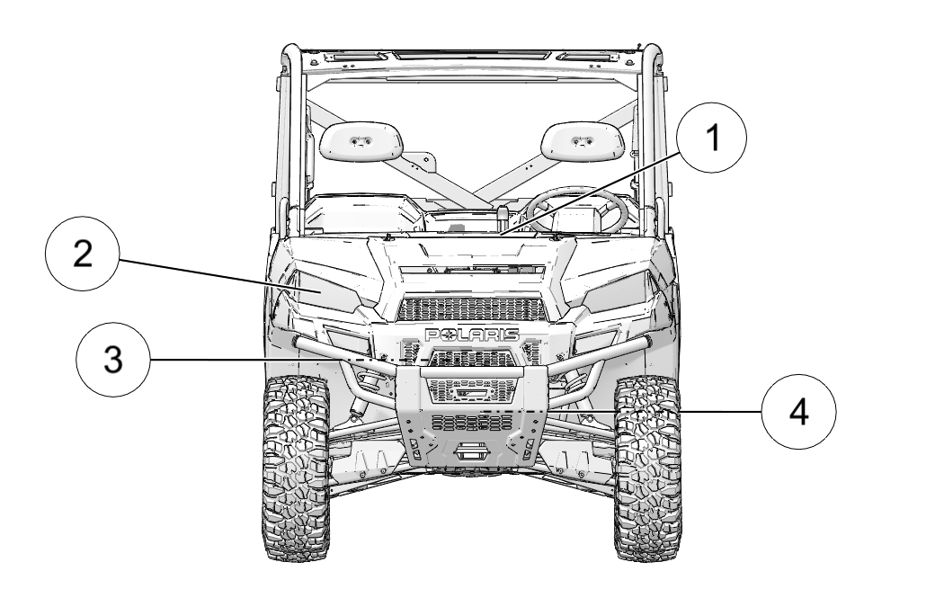
1 Console
2 Headlights
3 Radiator
4 Front Bumper / Brush Guard
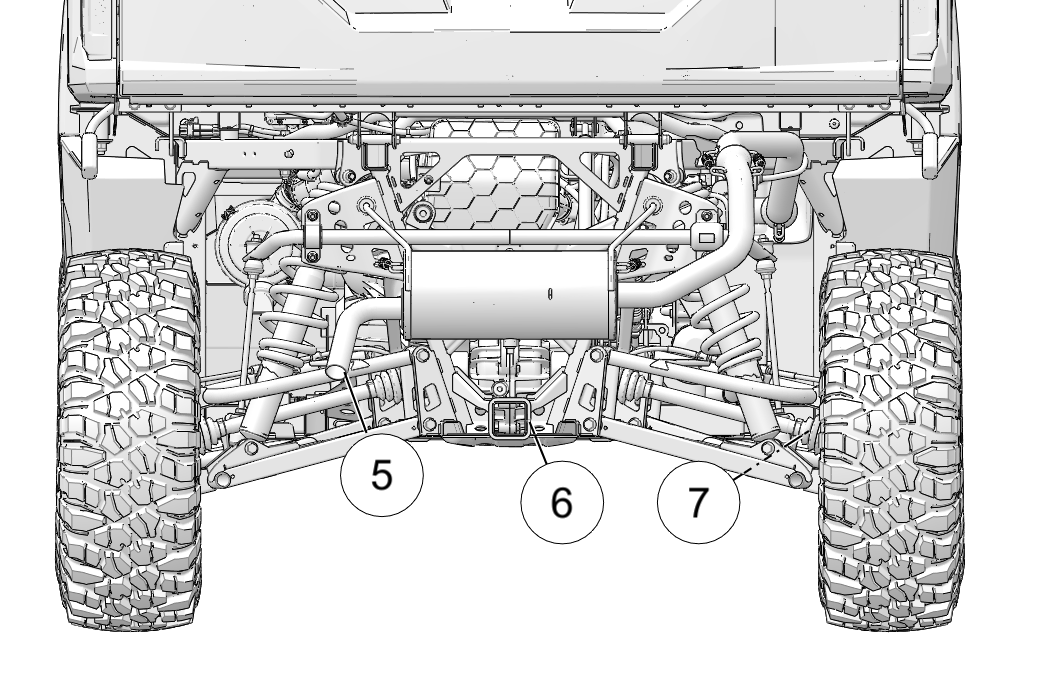
5 Muffler (Spark Arrester)
6 Receiver Hitch
7 CV Boot / Rear Caliper
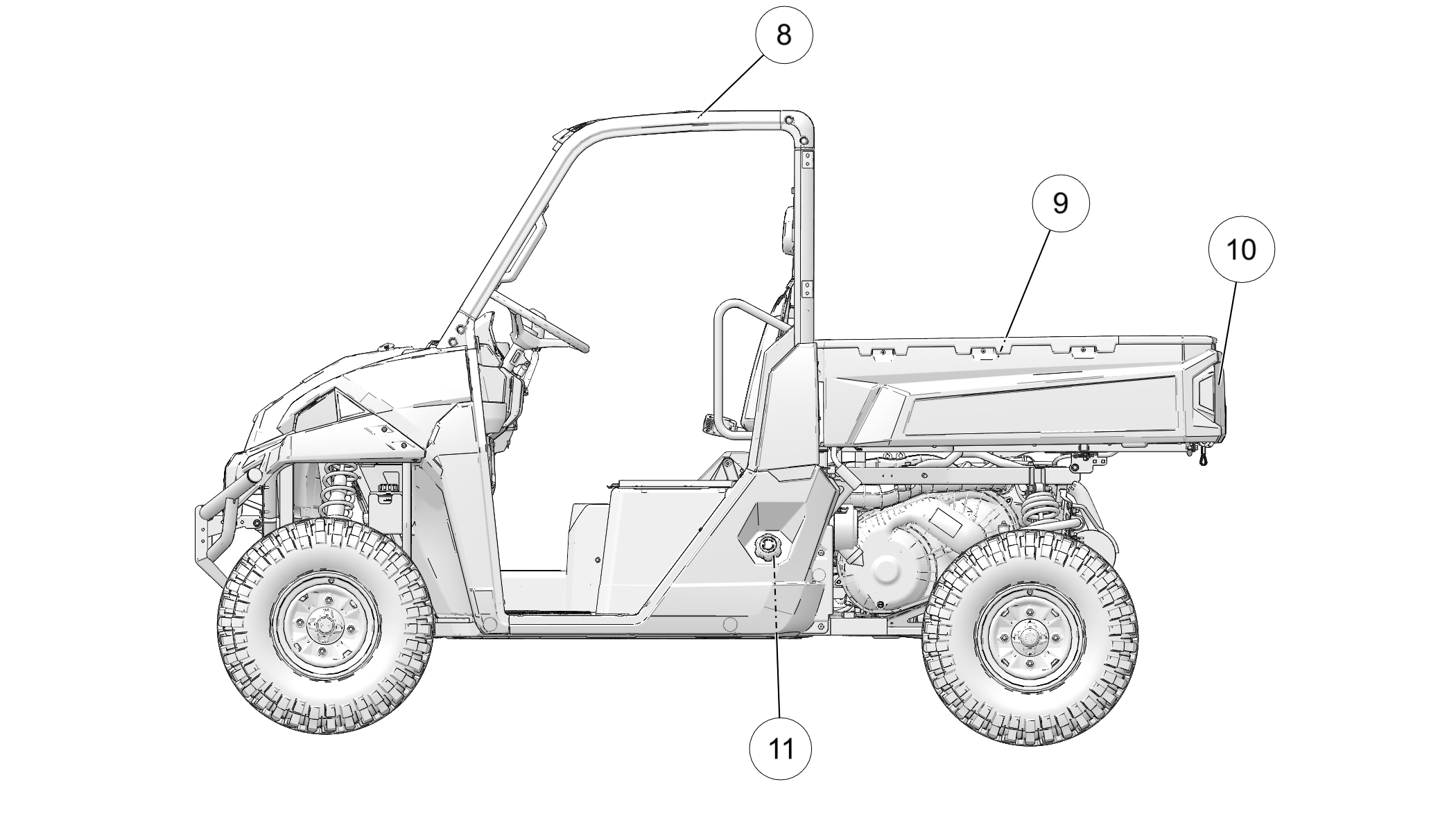
8 ROPS Cab Frame
9 Cargo Box
10 Tailgate
11 Fuel Cap
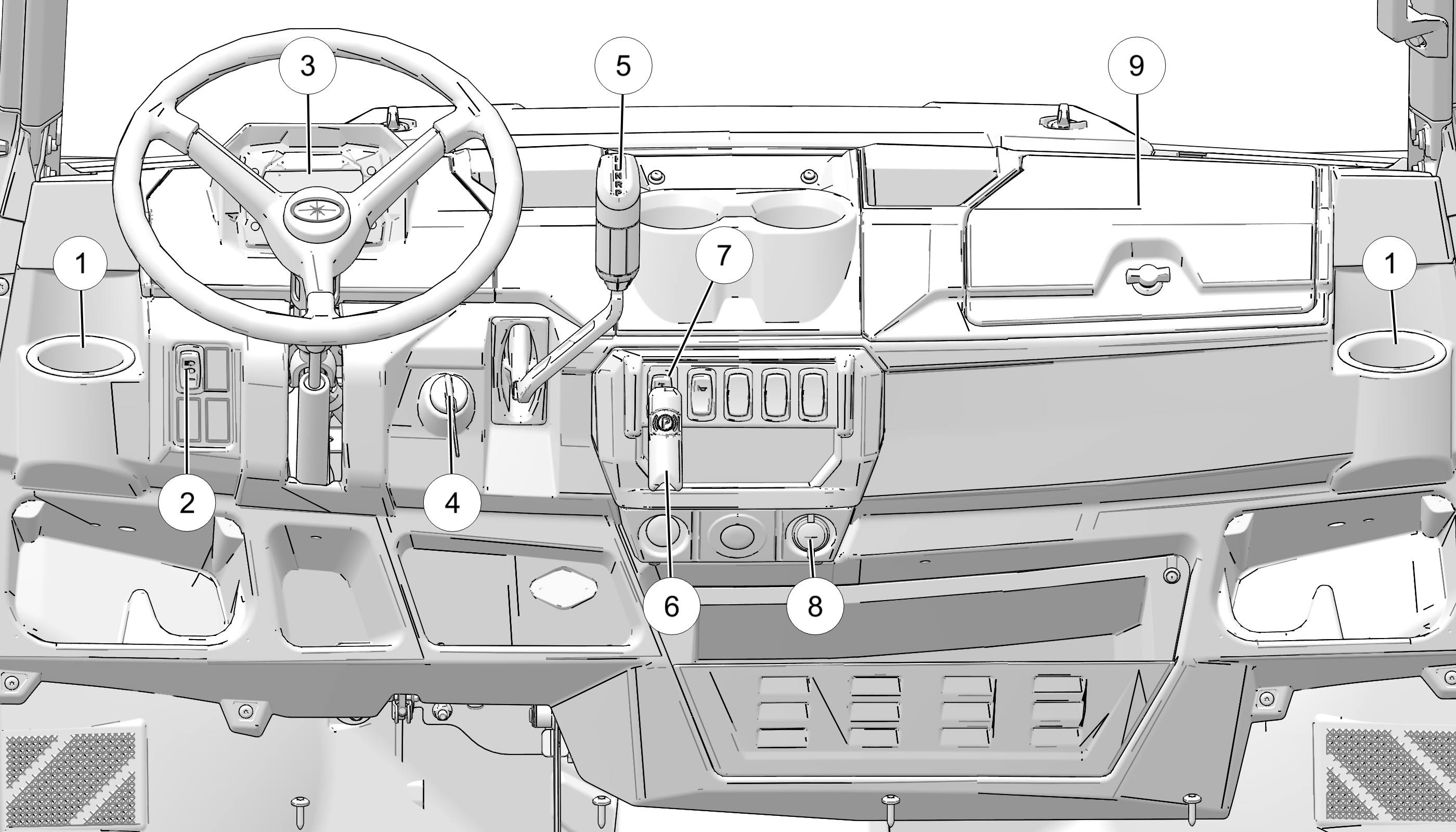
1 Cup Holder
2 Light Switch
3 Instrument Cluster
4 Ignition Switch
5 Gear Selector (Shifter)
6 Park Brake
7 AWD Switch
8 Auxiliary Outlet
9 Storage Compartment
The auxiliary outlet can be used to power standard 12V accessories like a cell phone charger or a power inverter up to 120 watts. Crew models have a second auxiliary outlet on switched power located in the center console between the rear seats. The passenger side outlet (and the rear outlet on crew models) switch on and off with the vehicle. These outlets cannot be used to charge the battery because they disconnect when the vehicle is off.

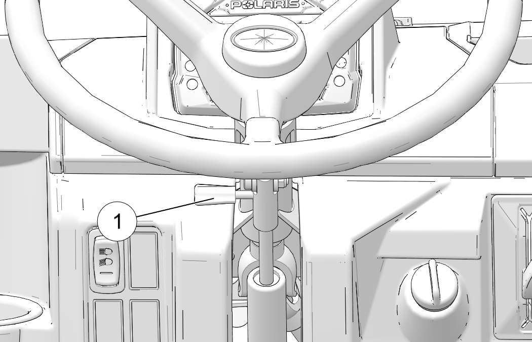
The steering wheel can be tilted upward or downward for rider preference. Lift and hold the adjustment lever 1 toward you while moving the steering wheel upward or downward. Release the lever when the steering wheel is at the desired position.
Low gear is the primary driving range for the PRO XD. High gear is intended for use on hard-packed surfaces with light loads. Using high gear for heavy loads, hilly terrain or in wet, muddy conditions will increase the chance of drive belt spinning. An alarm will sound if the vehicle detects belt spin. See the Drive Belt Wear/Spin section on Drive Belt Wear/Spin.
H: High Gear
L: Low Gear
N: Neutral
R: Reverse
P: Park
To shift gears, brake to a complete stop. When the engine is idling, move the lever to the desired gear.
Always shift into low gear for any of the following conditions.
Operating in rough terrain or over obstacles
Loading the vehicle onto a trailer
Towing loads
Driving frequently at low RPM or at ground speeds below 7 mph (11 kph)
Putting the vehicle into reverse will automatically activate the reverse alert beeper.
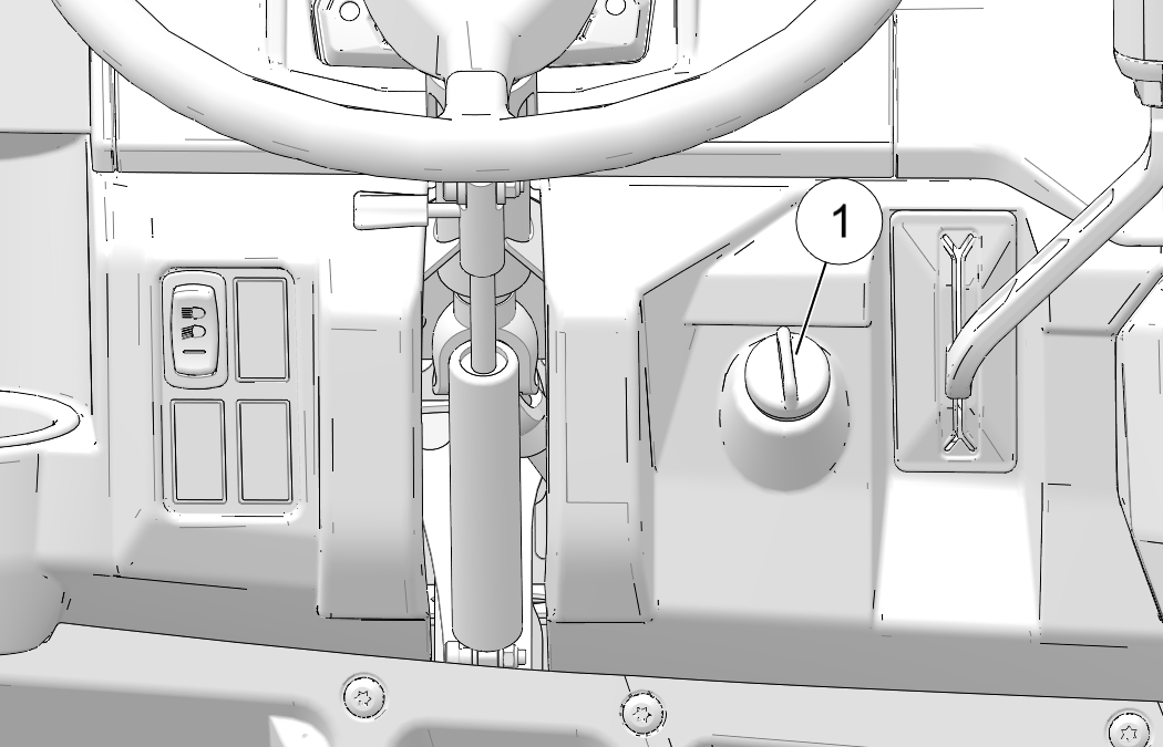
Always apply the service brakes before engaging or releasing the park brake 1. To help prevent the vehicle from rolling, set the park brake when parking the vehicle. When the park brake is set and the park brake indicator is illuminated, an alarm will sound if pressure is put on the throttle pedal.
To set the park brake, apply the brakes. Pull the park brake lever towards yourself as far as possible.
To release the park brake, apply the brakes. Turn the park brake lever counterclockwise and push it in as far as possible.
The ignition switch is a three-position, key-operated switch. The key can be removed from the switch when it is in the OFF position.
| OFF | The engine is off. Electrical circuits are off, except for the driver’s side auxiliary outlet and the Pulse Bar. |
| ON | Vehicle is on. All electrical equipment can be used. When first keyed on, glow plugs activate for 12 seconds and then deactivate. The indicator on the gauge displays when glow plugs are active. |
| START | Turn the key to the START position to engage the starter. The key returns to the ON position when released. |
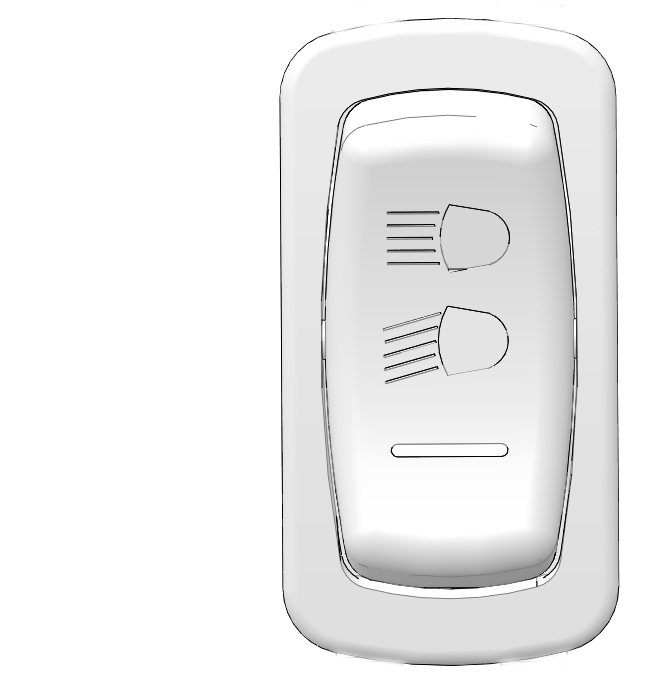
The ignition switch key must be in the ON/RUN position to operate the headlights. Press the top of the switch to place the headlights on high beam. Move the switch to the center position to place the headlights on low beam. Press the bottom of the switch to turn off the headlights.
The Driveline Mode Switch has three positions: All Wheel Drive (AWD), Differential Lock/Two Wheel Drive (2WD) and Off (Turf Mode).
1 AWD: Press the top of the switch to engage All Wheel Drive (AWD).
2 2WD: Move the switch to the center position to lock the differential and operate in two wheel drive (2WD).
3 TURF Mode: Press the bottom of the switch for Turf Mode (unlocked differential power). In Turf Mode, the rear drive wheels operate independently depending on tire traction. This mode of operation is well suited to turf driving or when active traction is not needed.

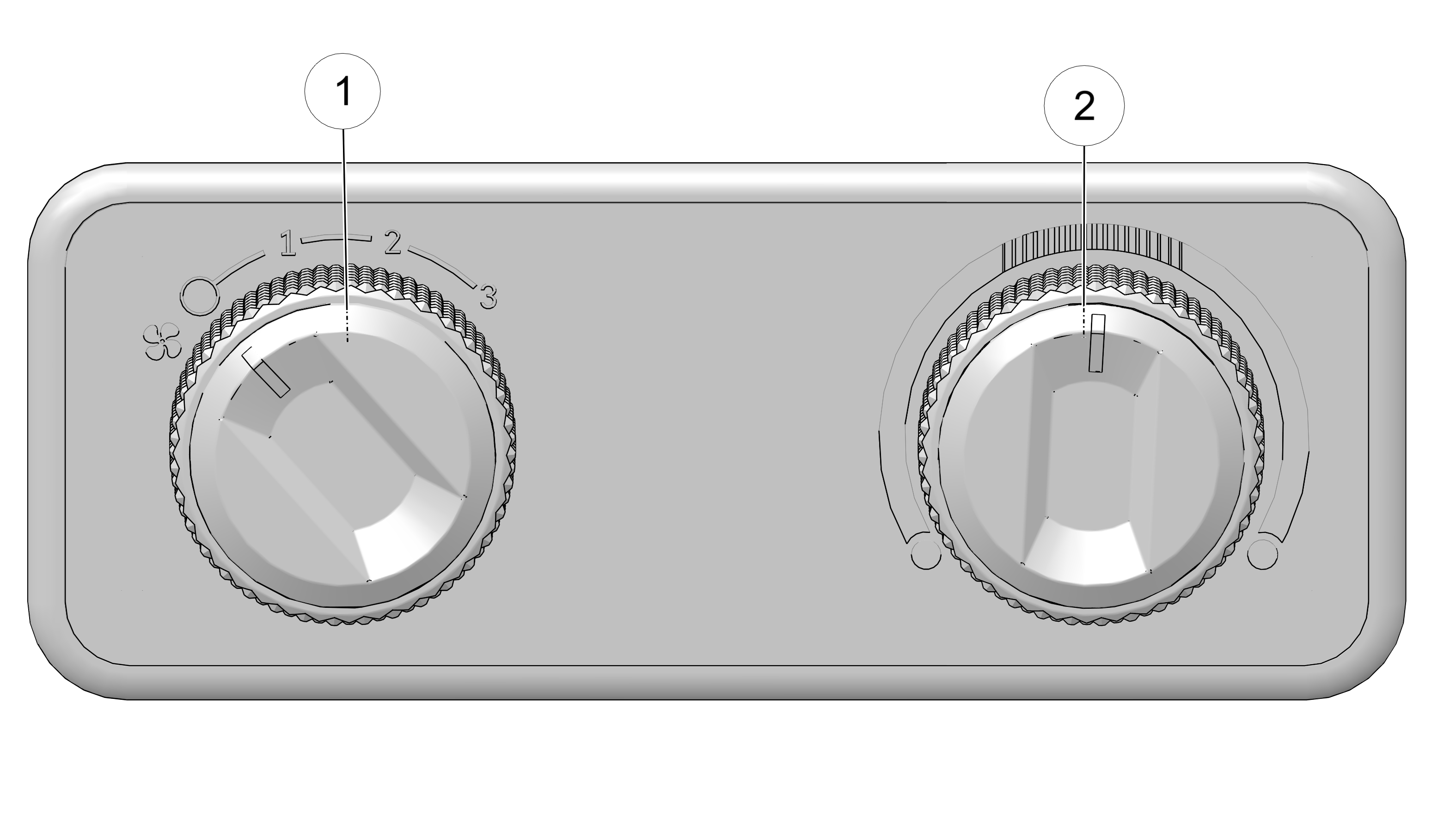
To operate the cab heater, rotate the fan control 1 to
the desired fan speed setting. The far left setting turns the fan
off.
Adjust the temperature by rotating the temperature
control 2 to the desired heat setting. Rotate the control
clockwise to increase heat or counter-clockwise to decrease heat.
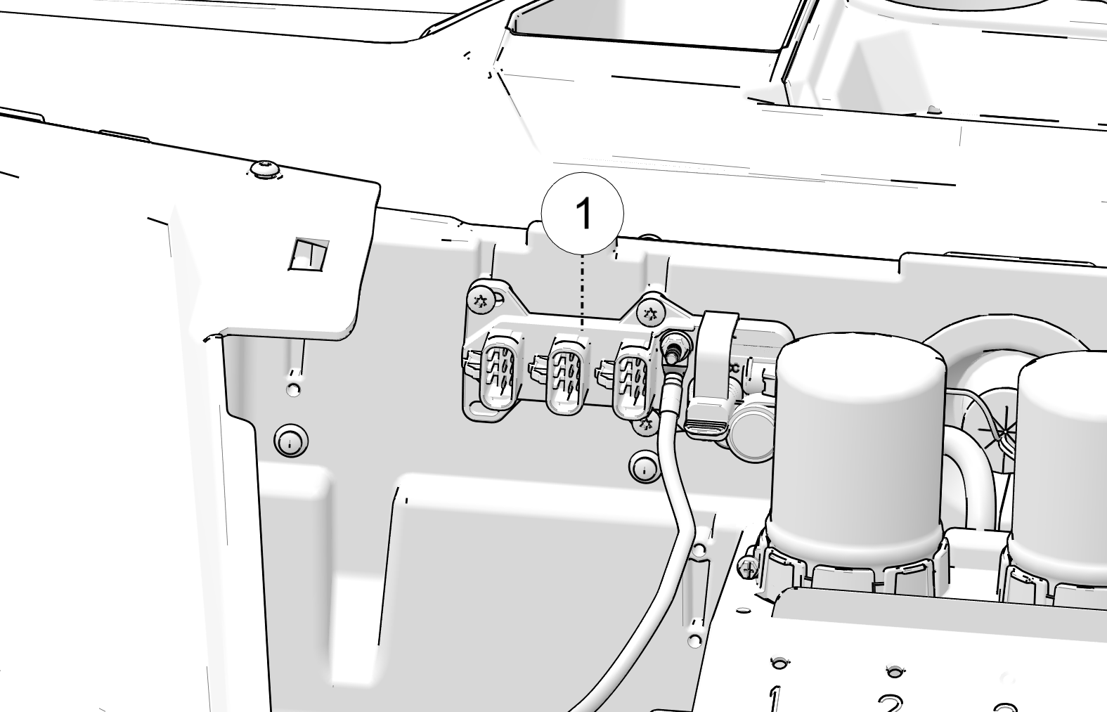
The Pulse Bar 1 is located under the hood and can be used to connect any Pulse Bar accessory to the vehicle. The Pulse Bar receives constant and switched power from the battery, so that accessories may be powered whether the vehicle is on or off.
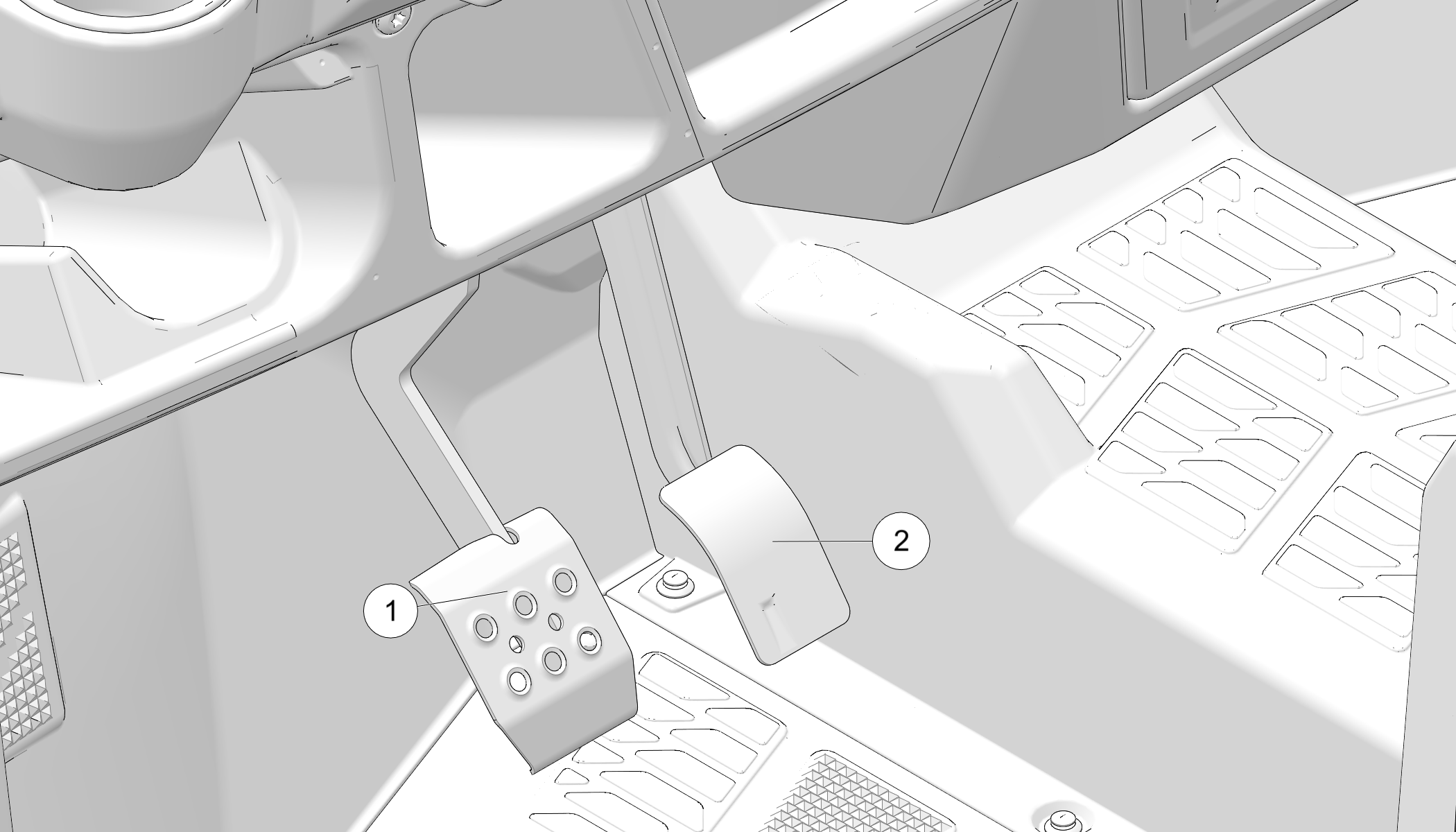
Depress the brake pedal 1 to slow or stop the vehicle. Apply the brakes while starting the engine.
When the brake pedal is depressed, the brake light comes on. Check the brake light before each ride.
Turn the ignition switch to the ON position.
Apply the brakes. The brake light should come on after about 0.4 in (10 mm) of pedal travel.
Push the throttle pedal 2 down to increase engine speed. Spring pressure returns the pedal to the rest position when released. Always check that the throttle pedal returns normally before starting the engine.
The electrical compartment is located under the center rear-most seat. Never use this area for storage. The battery is located under the passenger seat. Never use this area for storage.
Always make sure all seats are properly installed and securely latched before operating. Push down firmly on the rear of each seat until the latch pins are fully seated into the grommets.
To access the under-seat area, pull the rear edge of a seat upward to release the latch pins from the grommets. Then roll the seat forward.
Electronic power steering engages when the ignition key is turned to the ON position. EPS remains engaged whether the vehicle is moving or idle.
To conserve battery power, the EPS will shut down 5 minutes after the engine is stopped if the key remains in the ON position.
The EPS warning indicator will illuminate to indicate the EPS has shut down. See your POLARIS dealer, or other qualified person, as soon as possible for repair. Continued operation could result in permanent damage to the EPS unit and increased steering effort.
The Belt Slip Alarm will sound if the vehicle senses or detects belt spin (engine RPM without ground speed). The instrument cluster will also scroll the message “belt damage occurring”. If the alarm continues to sound frequently, shift to low gear.
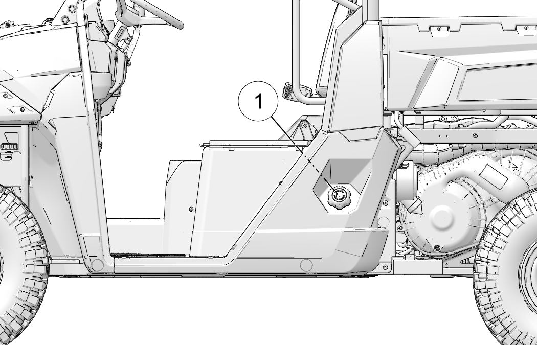
The fuel tank filler cap 1 is located on the left-hand side of the vehicle near the driver’s seat. Use only the recommended diesel fuel.
The Occupant Protection Structure (OPS) on this vehicle meets ANSI®/OPEI B71.9 standards. Always have your authorized dealer thoroughly inspect the OPS if it ever becomes damaged in any way.
No device can assure occupant protection in the event of a rollover. Always follow all safe operating practices outlined in this manual to avoid vehicle rollover.
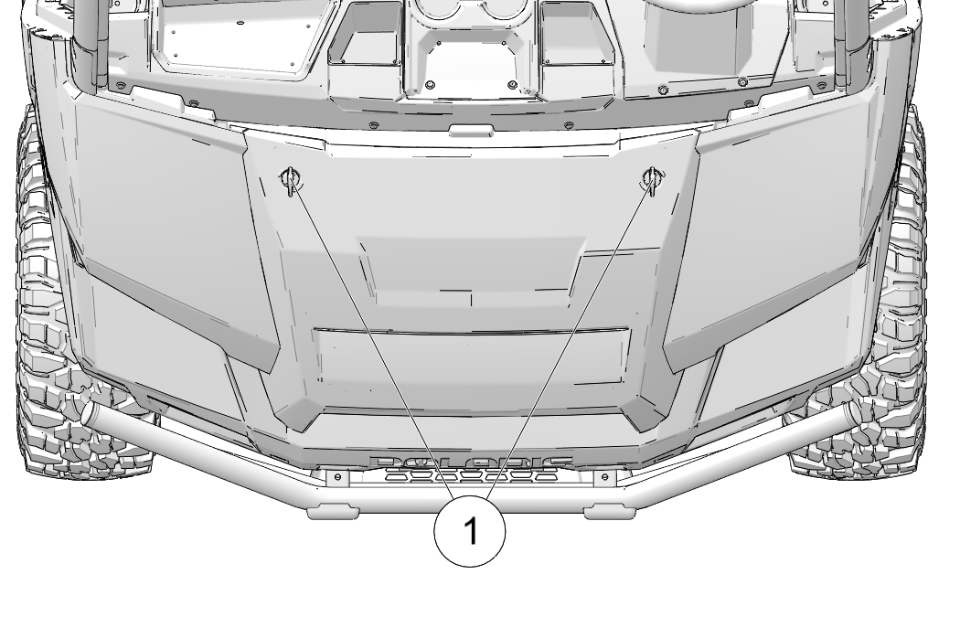
To remove the hood, rotate the hood latches 1 1/4-turn and lift the hood away from the vehicle.
This vehicle is equipped with a receiver hitch bracket for a trailer hitch. Trailer towing equipment is not supplied with this vehicle.
To avoid injury and property damage, always heed the warnings and towing capacities.
This POLARIS vehicle is equipped with three-point lap and diagonal seat belts on all seats. Always make sure the seat belts are secured for all riders before operating.
To wear the seat belt properly, follow this procedure:
For 3-point belts with D loops 2, pull the seat belt latch downward and across your chest toward the buckle 1 at the inner edge of the seat. The belt should fit snugly across your hips and diagonally across your chest. Make sure the belt is not twisted.
Push the latch plate into the buckle until it clicks.
Release the strap, it will self-tighten.
To release the seat belt, press the square red button in the buckle’s center.
Inspect all seat belts for proper operation before each use of the vehicle.
Push the latch plate into the buckle until it clicks. The latch plate must slide smoothly into the buckle. A click indicates that it's securely latched.
Push the red release latch in the middle of the buckle to make sure it releases freely.
Pull each seat belt completely out and inspect the full length for any damage, including cuts, wear, fraying or stiffness. If any damage is found, or if the seat belt does not operate properly, have the seat belt system checked and/or replaced by an authorized POLARIS dealer.
To clean dirt or debris from the seat belts, sponge the straps with mild soap and water. Do not use bleach, dye or household detergents.
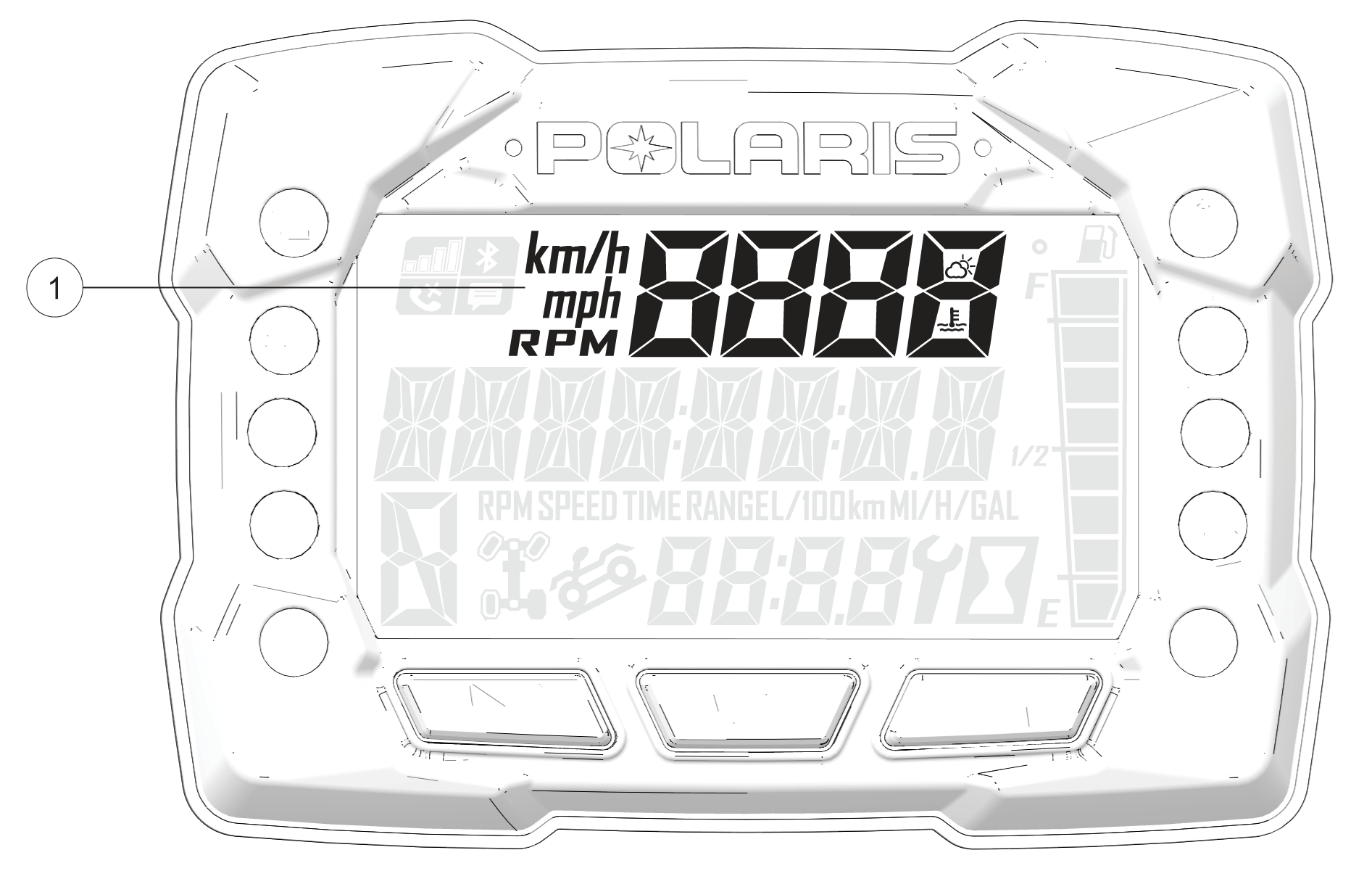
The use of a high pressure washer may damage the instrument cluster. Wash the vehicle by hand or with a garden hose using mild soap. Do not use alcohol to clean the instrument cluster. Do not allow insect sprays to contact the lens. Immediately clean off any gasoline that splashes on the instrument cluster.
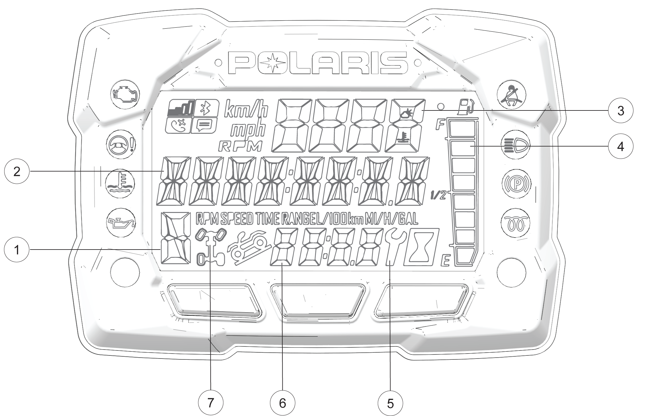
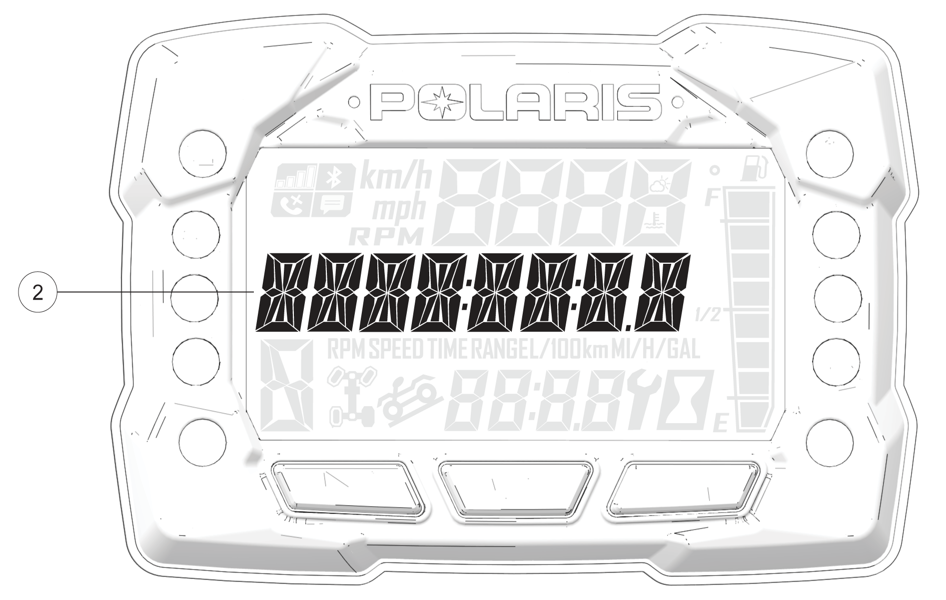
| 1 Gear Indicator |
H = High Gear L = Low Gear N = Neutral R = Reverse Gear P = Park -- = Gear Signal Error (or shifter between gears) |
| 2 Display Area 2 | This area displays odometer, trip meter, trip meter 2, voltage, engine temperature, engine hour meter, programmable service hour interval, ground speed, or engine RPM. |
| 3 Display Area 1 | This area displays engine RPM, ground speed, or coolant temperature. |
| 4 Fuel Gauge | The segments of the fuel gauge show the level of fuel in the fuel tank. When the last segment clears, a low fuel warning is activated. All segments including the fuel icon will flash. Refuel immediately. |
| 5 Service Indicator | A flashing wrench symbol alerts the operator that the preset service interval has been reached. Your POLARIS dealer can provide scheduled maintenance. See Service Hours for more information. |
| 6 Clock | The clock displays time in a 12-hour or 24-hour format. |
| 7 Driveline Mode Indicator | Segments of the indicator illuminate based on drive mode engaged. |
| Indicator | Icon | Function |
| Check Engine |
|
This lamp illuminates when the ECM detects a Diagnostic Trouble Code in the engine management system. Do not operate the vehicle if this warning appears. Serious engine damage could result. Your authorized POLARIS dealer can assist. This lamp will also illuminate if the vehicle is keyed on but not started; it will turn off once the vehicle is started. |
| EPS Warning (if equipped) |
|
This lamp illuminates to indicate that EPS has shut down. EPS shuts down automatically 5 minutes after the engine is turned off if the key remains in the ON position. Turn the key off and on to reset the unit. If the light remains on after starting the engine, the EPS system is inoperative. Your POLARIS dealer can assist. |
| Engine Hot |
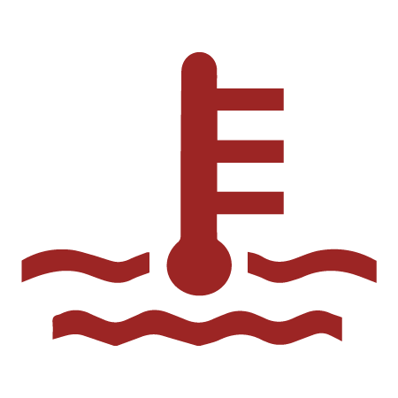
|
This lamp illuminates to indicate an overheated engine. If the indicator flashes, a severe overheating condition exists and the engine will shut down automatically. The vehicle will not start again until the engine has sufficiently cooled down. Whenever this lamp illuminates, the engine load should be reduced in any way possible to avoid overheating and shutting down the engine. |
| Low Oil Pressure |
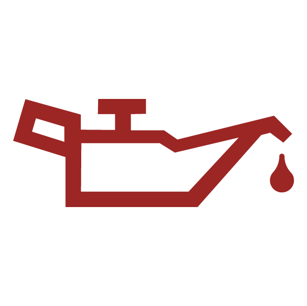
|
This lamp illuminates if engine oil pressure drops below safe operating pressure. If this lamp illuminates while the engine is running, turn the engine off as soon as safely possible and check the oil level. If the oil level is correct and the lamp remains on after the engine is restarted, turn the engine off immediately. |
| Helmet/Seat Belt |
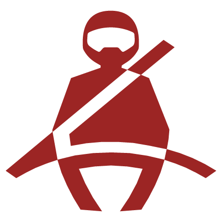
|
This lamp flashes for several seconds when the key is turned to the ON position. The lamp will keep flashing as long as riders’ seat belts are not connected. |
| High Beam |

|
This lamp illuminates when the headlamp switch is set to high beam. |
| Park Brake Indicator |

|
This lamp illuminates when the park brake is active. |
| Glow Plug Indicator |

|
This lamp illuminates when the glow plugs are active. |
Pressing the MODE button will change the information displayed in Area 1 1.
Speed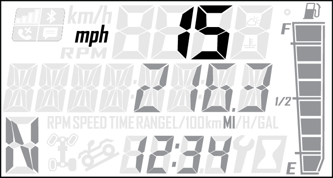
Engine Temperature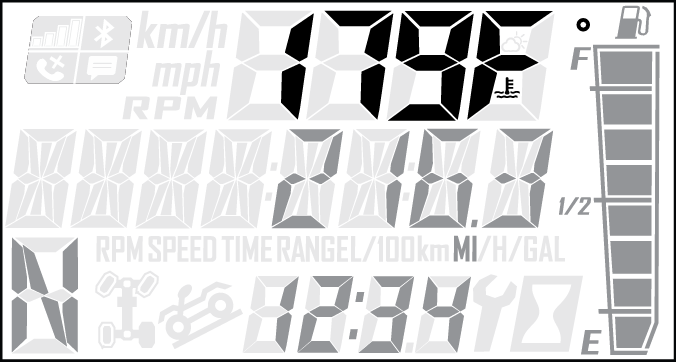
RPM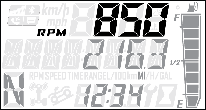
Ambient Temperature (Optional)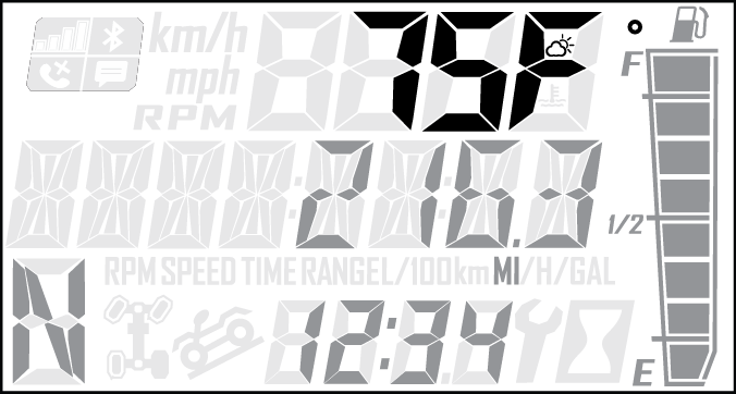
Toggle the Up/Down buttons to change the information displayed in Area 2 2.
Odometer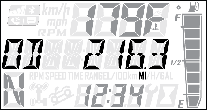
Engine Temperature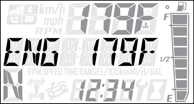
Trip 1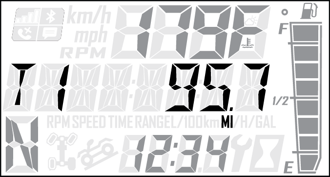
Ambient Temperature (Optional)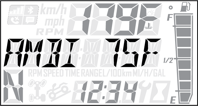
Trip 2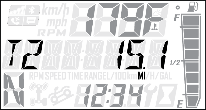
RPM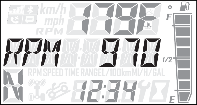
Voltage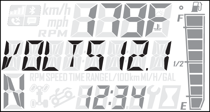
Speed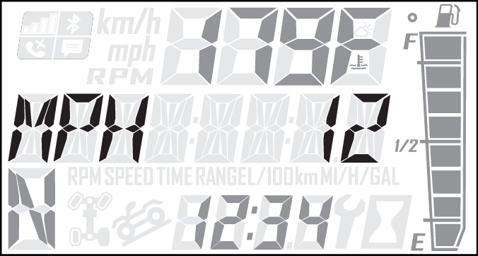
Engine Hours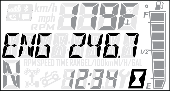
Service Hours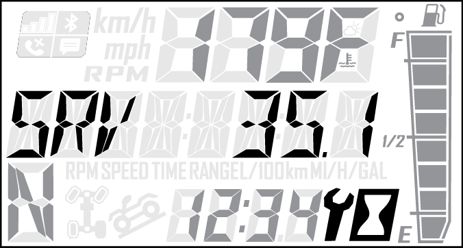
Press and hold the MODE button to enter the Options Menu.
| Options Menu | Notes |
|---|---|
| Diagnostic Codes |
Only displays if fault codes are present or stored |
| Units - Distance |
Select MPH or KPH |
| Units - Temp |
Select between °F and °C |
| Clock |
Select between 12H or 24H, and set time |
| Backlight Color |
Select between Blue or Red |
| Backlight Level |
Set backlight brightness level |
| Service Hours |
View/Set Service hours |
| Exit Menu |
Exit |
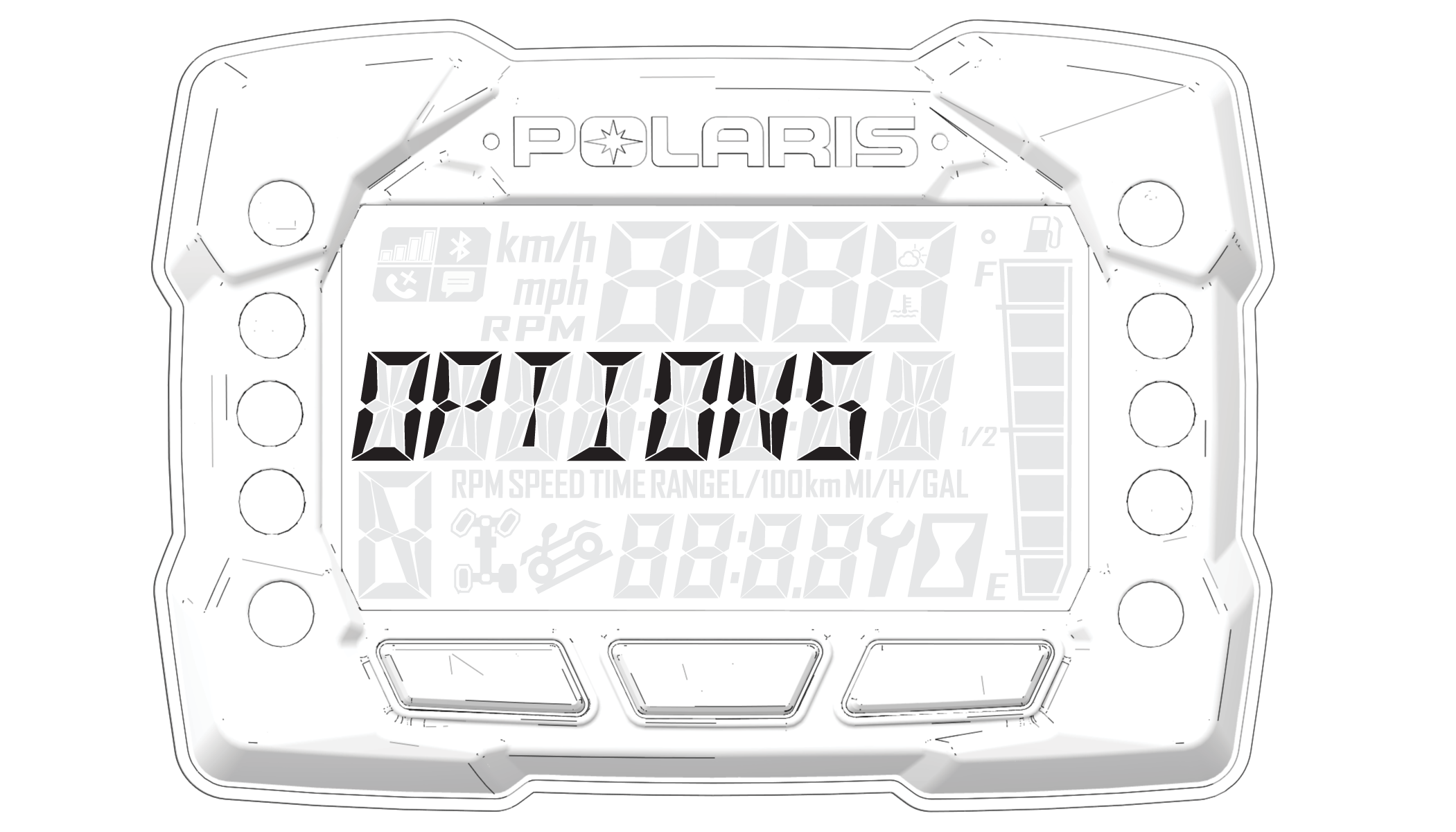
Press and hold the MODE button to enter the Options Menu.
“OPTIONS” will display on the screen for 3 seconds before showing first menu item.
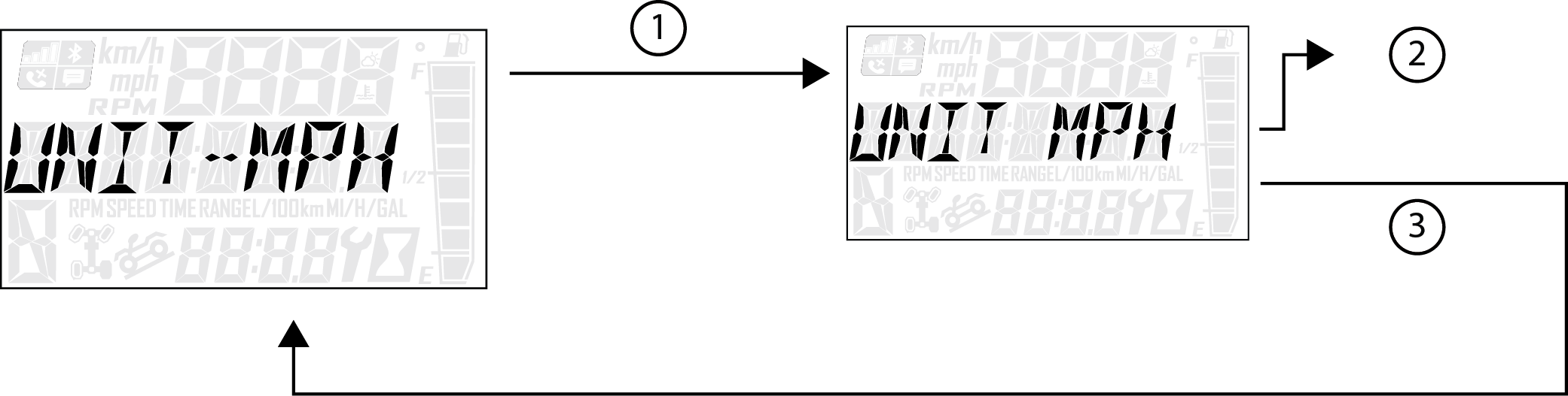
Select “Units-Distance” from the Options Menu by pressing the MODE button.
Reference the image shown above:
1 Press the MODE button.
2 Toggle the Up/Down Buttons to change the units (MPH or KPH)
3 With the correct unit displayed, press the MODE button which will set the unit and return to the Options Menu.
To exit the Options Menu the user can select Exit Menu function from Options Menu, can hold MODE Button and exit out of Options Menu, or not press any button for 10 seconds, which will exit out of the Options Menu.
Press and hold the MODE button to enter the Options Menu.
“OPTIONS” will display on the screen for 3 seconds before showing first menu item.
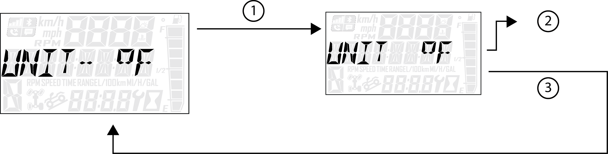
Select “Units - Temp” from the Options Menu by pressing the MODE button.
Reference the image shown above:
1 Press the MODE button.
2 Toggle the Up/Down Buttons to change the units (°F or °C)
3 With the correct unit displayed, press the MODE button which will set the unit and return to the Options Menu.
To exit the Options Menu the user can select Exit Menu function from Options Menu, can hold MODE Button and exit out of Options Menu, or not press any button for 10 seconds, which will exit out of the Options Menu.
Press and hold the MODE button to enter the Options Menu.
“OPTIONS” will display on the screen for 3 seconds before showing first menu item.
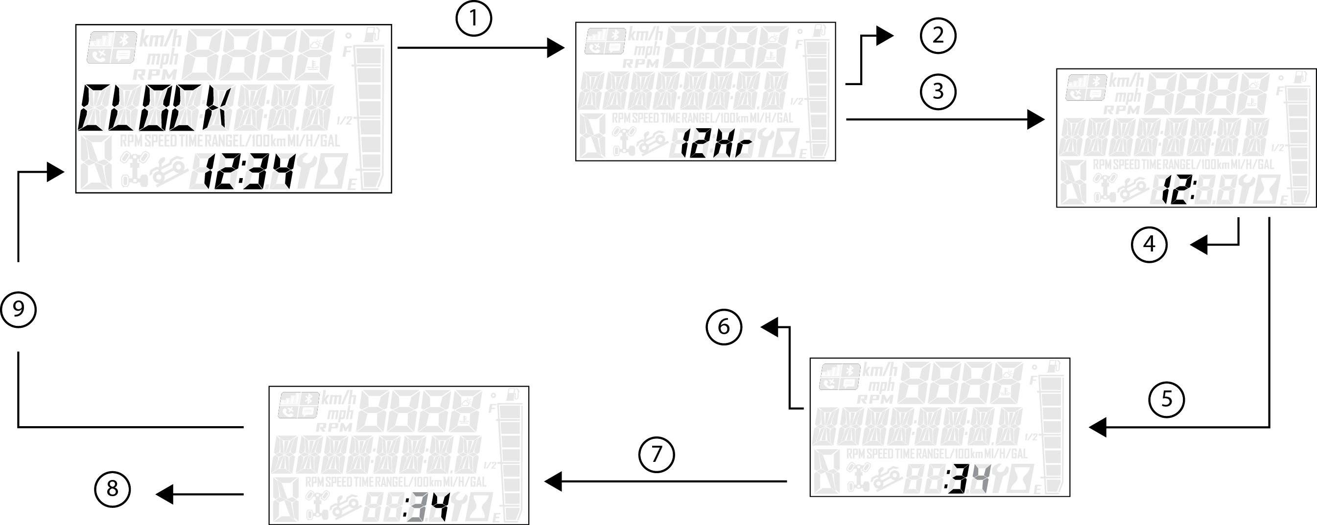
Select “Clock” from the Options Menu by pressing the MODE button.
Reference the image shown above:
1 Press the MODE button.
2 Toggle the Up/Down Buttons to change the units (12H or 24H)
3 With the correct unit displayed, Press the MODE button which will set the unit.
4 Toggle the Up/Down Buttons to change the units (Cycles Hours)
5 With the correct unit displayed, Press the MODE button which will set the unit.
6 Toggle the Up/Down Buttons to change the units (Cycles 10s of Minutes)
7 With the correct unit displayed, Press the MODE button which will set the unit.
8 Toggle the Up/Down Buttons to change the units (Cycles 1s of Minutes)
9 With the correct unit displayed, Press the MODE button which will set the unit and return to the Options Menu.
To exit the Options Menu the user can select Exit Menu function from Options Menu, can hold MODE button and exit out of Options Menu, or not press any button for 10 seconds, which will exit out of the Options Menu.
Press and hold the MODE button to enter the Options Menu.
“OPTIONS” will display on the screen for 3 seconds before showing first menu item.
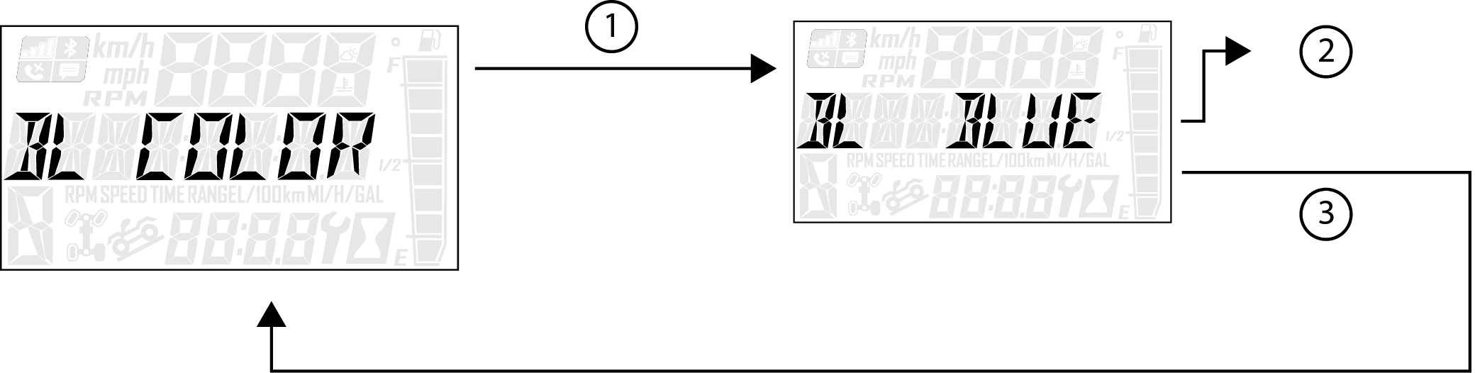
Select “Backlight Color” from the Options Menu by pressing the MODE button.
Reference the image shown above:
1 Press the MODE button.
2 Toggle the Up/Down Buttons to change the units (Blue or Red)
3 With the correct unit displayed, Press the MODE button which will set the unit and return to the Options Menu.
To exit the Options Menu the user can select Exit Menu function from Options Menu, can hold MODE Button and exit out of Options Menu, or not press any button for 10 seconds, which will exit out of the Options Menu.
Press and hold the MODE button to enter the Options Menu.
“OPTIONS” will display on the screen for 3 seconds before showing first menu item.
Select “Backlight Level” from the Options Menu by pressing the MODE button.
Reference the image shown above:
1 Press the MODE button.
2 Toggle the Up/Down Buttons to change the units (Increase or Decrease Level)
3 With the correct unit displayed, Press the MODE button which will set the unit and return to the Options Menu.
To exit the Options Menu the user can select Exit Menu function from Options Menu, can hold MODE Button and exit out of Options Menu, or not press any button for 10 seconds, which will exit out of the Options Menu.

Press and hold the MODE button to enter the Options Menu.
“OPTIONS” will display on the screen for 3 seconds before showing first menu item.
Select “Service Hours” from the Options Menu by pressing the MODE button.
Reference the image shown above:
1 Press the MODE button.
2 Toggle the Up/Down Buttons to change the units (0, 5, 10 - 95, 100)
3 With the correct unit displayed, press the MODE button, which will set the unit and return you to the Options Menu.
To reset service hours after they have counted down to "0.0", reselect the existing setpoint or select a new service hour value.
To exit the Options Menu the user can select Exit Menu function from Options Menu, can hold MODE Button and exit out of Options Menu, or not press any button for 10 seconds, which will exit out of the Options Menu.
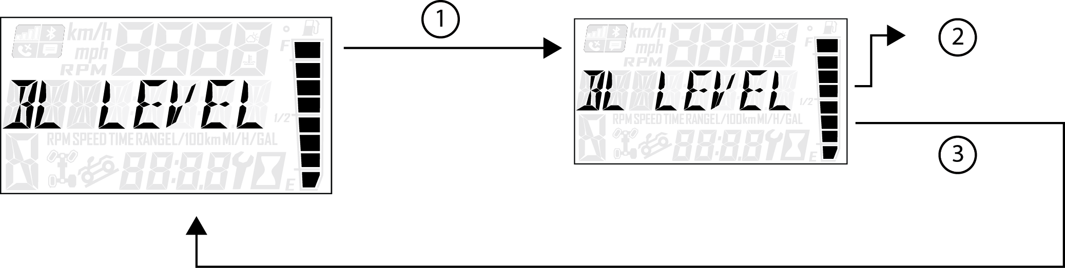
Diagnostic Code Screen will show available MIL that has come on during that ignition cycle.
Press and hold the MODE button to enter the Options Menu.
“OPTIONS” will display on the screen for 3 seconds before showing first menu item.
Select “Diagnostic Codes” from the Options Menu by pressing the MODE button.
Toggle the Up/Down Buttons to cycle through Code(s).
This option will only be available if a fault code was set or is active during the current ignition key 'on' cycle. Turning off the ignition will clear any saved fault codes from the gauge.
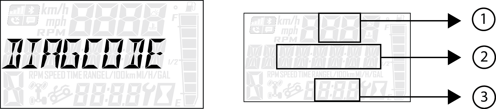
Reference the image shown above:
1 Area A will Display FMI (XX)
2 Area B will Display SPN (XXXXXX)
3 Clock Area will Display Count (XXX)
To exit the Options Menu the user can select Exit Menu function from Options Menu, can hold MODE Button and exit out of Options Menu, or not press any button for 10 seconds, which will exit out of the Options Menu.
|
Diagnostic Codes |
|||
|---|---|---|---|
|
Component |
Condition |
SPN |
FMI |
|
Low oil pressure switch fault |
CAN message 65390 Timeout error |
100 |
11 |
|
Current below normal or open circuit |
100 |
5 |
|
|
Engine Temperature Sensor |
Voltage above normal, or shorted to high source |
110 | 3 |
|
Voltage above normal, or shorted to high source |
110 | 4 | |
|
System Power (Battery Potential/Power Input) |
Data valid but below normal operational range - most severe level | 168 | 1 |
|
Voltage above normal, or shorted to high source |
168 | 3 | |
|
Voltage below normal, or shorted to low source |
168 | 4 | |
| Gear Sensor Signal |
Voltage below normal, or shorted to low source |
523 | 4 |
| Rear Differential Output |
Voltage above normal, or shorted to high source |
746 |
3 |
|
Voltage below normal, or shorted to low source |
746 |
4 | |
|
Current below normal or open circuit |
746 |
5 | |
| Fan Relay Driver Ckt. |
Voltage above normal, or shorted to high source |
1071 |
3 |
|
Voltage below normal, or shorted to low source |
1071 |
4 | |
|
Current below normal or open circuit |
1071 |
5 | |
| Fuel Pump Driver Ckt. |
Voltage above normal, or shorted to high source |
1347 |
3 |
|
Voltage below normal, or shorted to low source |
1347 |
4 | |
|
Current below normal or open circuit |
1347 |
5 | |
| ECU Output Supply Voltage 1 |
Voltage above normal, or shorted to high source |
3597 |
3 |
|
Voltage below normal, or shorted to low source |
3597 |
4 | |
| ECU Output Supply Voltage 3 |
Voltage above normal, or shorted to high source |
3598 |
3 |
|
Voltage below normal, or shorted to low source |
3598 |
4 | |
| All Wheel Drive Control Circuit |
Voltage above normal, or shorted to high source |
520207 |
3 |
|
Voltage below normal, or shorted to low source |
520207 |
4 | |
|
Current below normal or open circuit |
520207 |
5 | |
| Brake failure lamp faults |
Voltage above normal, or shorted to high source |
520214 |
3 |
|
Voltage below normal, or shorted to low source |
520214 |
4 | |
|
Current below normal or open circuit |
520214 |
5 | |
| Glow Plug Relay Driver Circuit |
Voltage above normal, or shorted to high source |
520272 |
3 |
|
Voltage below normal, or shorted to low source |
520272 |
4 | |
|
Current below normal or open circuit |
520272 |
5 | |
| Brake switch (1 or 2 indeterminable) | Data erratic, intermittent or incorrect | 520285 | 2 |
| Engine Oil Pressure Sensor | Data valid but below normal operating range - least severe level | 524076 | 17 |
Failure to operate the vehicle properly can result in a collision, loss of control, accident or rollover, which may result in serious injury or death. Read and understand all safety warnings outlined in the safety section of this owner’s manual.
The break-in period for your new vehicle is the first 50 hours of operation. No single action on your part is as important as a proper break-in period. Careful treatment of a new engine will result in more efficient performance and longer life for the engine. Perform the following procedures carefully.
Excessive heat build-up during the first 3 hours of operation will damage close-fitted engine parts and drive components. Do not operate at full throttle or high speeds during the first 3 hours of use.
Fill the fuel tank with clean, fresh fuel.
Check the oil level. Add the recommended oil as needed to maintain the oil level in the safe operating range.
Complete the New Operator Driving Procedures.
Avoid aggressive use of the brakes.
Vary throttle positions. Do not operate at sustained idle.
Pull only light loads.
Perform regular checks on fluid levels, controls and areas outlined on the daily pre-ride inspection checklist.
During the break-in period, change both the oil and the filter at 50 hours or one month, and every 200 hours thereafter.
Check fluid levels of transmission and all gearcases after the first 50 hours of operation and every 200 hours thereafter.
Apply only moderate braking force for the first 50 stops. Aggressive or overly forceful braking when the brake system is new could damage brake pads and rotors.
Always break in the clutches and drive belt of new vehicles, as well as after a belt replacement.
A proper break-in of the clutches and drive belt will ensure a longer life and better performance. Break in the clutches and belt by operating at slower speeds during the break-in period as recommended. Pull only light loads. Avoid aggressive acceleration and high speed operation during the break-in period.
If a belt fails and you need to replace it, always clean all debris from the PVT intake and outlet duct, the clutch, and the engine components.
Do not allow anyone under 16 years of age or without a valid driver’s license to operate this vehicle.
Engine exhaust fumes are poisonous. Never start the engine or let it run in an enclosed area.
Never operate with accessories not approved by POLARIS for use on this vehicle.
Use caution and drive at reduced speeds in conditions of reduced visibility such as fog, rain and darkness. Clean headlights frequently and replace burned out headlamps promptly.
Always operate at a speed that's appropriate for the terrain, the visibility and operating conditions and your skills and experience. Never operate at excessive speeds. Never attempt wheelies, jumps, or other stunts. Keep both hands on the steering wheel or handlebars during operation.
Never consume alcohol or drugs before or while operating this vehicle.
Always use the size and type of tires specified for your vehicle. Always maintain proper tire pressure.
Never operate a damaged vehicle. After any rollover or accident, have a qualified service dealer inspect the entire machine for possible damage.
Never operate the vehicle on a frozen body of water unless you have first verified that the ice is sufficiently thick to support the weight and moving force of the vehicle, you and your cargo, together with any other vehicles in your party.
Do not touch hot exhaust system components. Always keep combustible materials away from the exhaust system.
Always remove the ignition key when the vehicle is not in use to prevent unauthorized use.
| Item | Remarks | Page |
|---|---|---|
|
Air Filter |
Inspect air filter, ensure it is properly installed; ensure air box cover is secured and fastened. Note: Air filter removal is not needed for visual inspection. |
Air Filter Inspection / Replacement |
|
Steering System |
Check for tightness/freeplay in the steering wheel when turned lock to lock |
Steering Inspection |
|
Front / Rear Suspension |
Visually inspect for damages to the control arms / trailing arms / bushings; check for leaking shocks |
- |
|
Tires |
Check for proper air pressure in all tires; visually inspect for damage; verify there is adequate tread depth |
Tire Tread Depth |
|
Wheels / Lug Nuts |
Ensure rim is not cracked or bent; verify proper lug torque |
Axle and Wheel Nut Torque Specifications |
|
Headlights / Taillights |
Ensure all lights are operational; adjust headlight aim, as needed |
Headlight Bulb Replacement |
|
Brake System |
Check brake fluid level is between MIN and MAX; ensure brake pedal is not soft when pushed; inspect for leaks |
Brakes |
|
Frame / Body Fasteners |
Visually inspect for loose body / frame fasteners |
- |
|
Engine Oil Level |
Verify oil level is in the SAFE range on the dipstick |
Oil Check |
|
Throttle |
Inspect for proper operation and smooth travel |
Throttle Freeplay |
|
Seat Belts |
Check length of belt for damage, check latches for proper operation |
Seat Belts |
|
Coolant Level |
Verify coolant level is filled to the FULL COLD mark on coolant reservoir (if engine is cold); inspect hoses and radiator for leaks |
Radiator Coolant Level |
|
Parking Brake |
Inspect operation |
Park Brake Lever |
|
Chassis / Engine Bay / Exhaust |
Remove grass, leaves, foreign matter, and other flammable material or debris, especially near the exhaust system. |
- |
POLARIS recommends the following diesel fuels for use in this vehicle:
Ultra Low Sulfur #2
#1 Diesel Fuel containing no more than 20% bio-diesel
For more information about recommended diesel fuels and the consequences of using bio-diesel fuel exceeding 20% bio- diesel, see Additional Technical Fuel Requirements below.
Diesel fuel should comply with the following world-wide specifications.
| Diesel Fuel Specification | Location |
|---|---|
|
ASTM D975 No. 1D S15, S500 No. 2D S15, S500 |
USA |
| EN590:96 | European Union |
| ISO 8217 DMX | International |
| BS 2869-A1 or A2 | United Kingdom |
| JIS K2204 Grade No. 2 | Japan |
| KSM-2610 | Korea |
| GB252 | China |
The fuel cetane number should be equal to 45 or higher.
The sulfur content must not exceed 0.5% by volume. Less than 0.5% is preferred. Especially in the U.S.A. and Canada, Ultra Low Sulfur fuel should be used.
Bio-Diesel fuels.
NEVER mix kerosene, used engine oil or residual fuels with diesel fuel.
Water and sediment in the fuel should not exceed 0.05% by volume.
Keep the fuel tank and fuel-handling equipment clean at all times.
Poor quality fuel can reduce engine performance and/or cause engine damage.
Fuel additives are not recommended. Some fuel additives may cause poor engine performance.
Ash content must not exceed 0.01% by volume.
Carbon residue content must not exceed 0.35% by volume. Less than 0.1% is preferred.
Total aromatics content should not exceed 35% by volume. Less than 30% is preferred.
PAH (polycyclic aromatic hydrocarbons) content should be below 10% by volume.
Metal content of Na, Mg, Si and Al should be equal to or lower than 1 mass ppm (test analysis method JPI-5S-44-95).
Lubricity: Wear mark of WS1.4 should be Max. 460μm (0.018 in.) at HFRR test.
In Europe and in the United States, as well as some other countries, non-mineral oil based fuel resources such as RME (Rapeseed Methyl Ester) and SOME (Soybean Methyl Ester), collectively known as FAME (Fatty Acid Methyl Esters), are being used as extenders for mineral oil derived diesel fuels.
These B20 diesel fuels must meet certain requirements:
The bio-fuels must meet the minimum specifications for the country in which they are used.
In Europe, bio-diesel fuels must comply with the European Standard EN14214.
In the United States, bio-diesel fuels must comply with the American Standard ASTMD-6751.2.
Bio-fuels should be purchased only from recognized and authorized diesel fuel suppliers.
Precautions and concerns regarding the use of bio-fuels:
Free methanol in FAME may result in corrosion of aluminum and zinc FIE components.
Free water in FAME may result in plugging of fuel filters and increased bacterial growth.
High viscosity at low temperatures may result in fuel delivery problems, injection pump seizures and poor injection nozzle spray atomization.
FAME may have adverse effects on some elastomers (seal materials) and may result in fuel leakage and dilution of the engine lubricating oil.
Even bio-diesel fuels that comply with a suitable standard as delivered will require additional care and attention to maintain the quality of the fuel in the equipment or other fuel tanks. It is important to maintain a supply of clean, fresh fuel. Regular flushing of the fuel system and/or fuel storage containers may be necessary.
The use of bio-diesel fuels that do not comply with the standards as agreed to by the diesel engine manufacturers and the diesel fuel injection equipment manufacturers, or bio-diesel fuels that have degraded as per the precautions and concerns above, may affect the warranty coverage of your engine.
B21 To B100 Bio-diesel Fuel Blend Usage
B21 to B100 bio-diesel is not approved for this POLARIS application.
Approved Engines
Only the Kubota® engine series listed below may operate with bio-diesel fuel concentrations up to B20 for POLARIS applications.
Kubota® 902D
Approved Fuel
Bio-diesel fuel blends up to B20 must comply with the following standards:
EN14214 (European standard) and/or ASTM D-6751 (American standard).
All applicable engines may operate with bio-diesel fuel up to a maximum B20 (20% bio- diesel blend) concentration.
Operating Conditions with B20 Bio-diesel Fuel Blends
Engine Warranty
Damages, performance or service concerns determined to be caused by the use of bio-diesel fuel not meeting the specifications outlined above are not considered to be defects in material or factory workmanship and are not covered under warranty. The same applies to damages or other concerns induced by not complying with the recommended operating conditions of Kubota® engines with bio-diesel fuel.
Diesel fuel is flammable and explosive under certain conditions.
NEVER refuel with the engine running.
Always refuel outdoors or in a well ventilated area.
Fill the fuel tank with diesel fuel ONLY. Filling the fuel tank with gasoline may result in a fire and will damage the engine.
Remove flammable material containers from the box before filling them with fuel.
Do not smoke or allow open flames or sparks in or near the area where refueling is performed or where fuel is stored.
Wipe up all spills immediately.
Keep sparks, open flames or any other form of ignition (match, cigarette, static electricity source) well away when refueling.
NEVER remove the fuel cap while the engine is running.
NEVER overfill the fuel tank. Do not fill the tank neck.
If fuel spills on your skin or clothing, immediately wash it off with soap and water and change clothing.
The fuel tank filler cap is located on the left side of the vehicle near the driver’s seat. Remove the cap and add the recommended fuel to the bottom of the filler neck. Do not overfill.
Cold weather operation can result in fuel gelling if the incorrect fuel type is used. Use the following fuel blending guideline to prevent this from occurring.
| Fuel Blending Guideline | ||
|---|---|---|
| Temperature | No. 2 | No. 1 |
|
+15 f (-9 c) |
100% | 0% |
|
Down to -20 f (-29 c) |
50% | 50% |
|
Below -20 f (-29 c) |
0% | 100% |
| Cold Starting Guidelines | ||||
|---|---|---|---|---|
|
Temp. |
+20 f (-7 c) to +15 f (-9 c) |
+15 f (-9 c) to +5 f (-15 c) |
+5 f (-15 c) to -20 f (-29 c) |
-20 f (-29 c) to -25 f (-32 c) |
|
Fuel |
#2 Diesel |
50/50 mix #1/#2 diesel |
#1 Diesel |
|
|
5W-40 Synthetic Diesel Engine Oil |
Optional |
Advised |
Required |
|
|
Block heater |
Optional |
Advised |
Required |
|
|
Battery condition/ connections |
Charged battery (12.8 VDC) |
|||
|
Proper glow plug usage (wait for the light) |
Wait for light at all temps |
|||
|
Oil pan heater |
Not needed |
Optional (helps to reduce cranking) |
||
If this vehicle will be operated when temperatures are in the +5 f (-15 c) to -25 f (-32 c) range, a block heater must be installed. Please see your dealer to purchase a block heater kit.
Bio-diesel blended fuel has unique qualities that should be considered before using it in this vehicle:
Cold weather conditions can lead to plugged fuel system components and hard starting.
Bio-diesel blended fuel is an excellent medium for microbial growth and contamination which can cause corrosion and plugging of fuel system components.
Use of bio-diesel blended fuel may result in premature failure of fuel system components, such as plugged fuel filters and deteriorated fuel lines.
Shorter maintenance intervals may be required, such as cleaning the fuel system and replacing fuel filters and fuel lines.
Using bio-diesel blended fuels containing more than 20% bio-diesel can affect engine life and cause deterioration of hoses, tubes, injectors, injector pump and seals.
Use the following guidelines if bio-diesel blended fuel is used:
Never use bio-diesel blended fuel containing more than 20% bio-diesel in this vehicle.
Ensure the fuel tank is as full as possible at all times to prevent moisture from collecting in the fuel tank.
Ensure that the fuel tank cap is securely tightened.
Clean up any spilled fuel immediately to prevent damage to painted surfaces.
Drain all water from the fuel filter daily before operating the vehicle.
Do not exceed the engine oil change interval. Extended intervals can result in engine damage.
Before vehicle storage, drain the fuel tank, refill with 100% petroleum diesel fuel, add fuel stabilizer and run the engine for at least 30 minutes.
Avoid operating in the presence of chemical gases or fumes.
Avoid operating in a corrosive atmosphere such as salt water spray.
NEVER operate the engine in a floodplain unless proper precautions are taken to avoid being subject to a flood.
NEVER expose the engine to the rain.
The standard range of ambient temperatures for the normal operation of Kubota® engines is from +5 f (-15 c) to +104 f (+40 c).
If the ambient temperature exceeds +104 f (+40 c), the engine may overheat and cause the engine oil to break down.
If the ambient temperature is between +5 f (-15 c) and -25 f (-32 c), POLARIS recommends the use of a block heater.
NEVER use an engine starting aid such as ether. Engine damage will result.
Before operating this vehicle in cold weather, review the cold weather operation information on the preceding pages. Always wait for the glow plug indicator light to turn off before cranking the engine.
Always start the engine outdoors or in a well-ventilated area.
Sit in the driver's seat and fasten the seat belt.
Place the transmission in PARK.
Apply the brakes. Do not press the throttle pedal while starting the engine.
Turn the ignition switch to the ON position and wait for the glow plug indicator light to turn off.
Turn the ignition key past the ON position to START. Engage the starter for a maximum of five seconds. Release the key when the engine starts.
If the engine does not start within five seconds, release the ignition switch and wait five seconds. Repeat steps 6 and 7 until the engine starts.
For maximum engine life, allow the engine to idle, without load, for 5 minutes. This will allow the engine components that operate at high temperatures, such as the exhaust system, to cool slightly before the engine is shut down.
Release the throttle pedal completely and brake to a complete stop.
Place the transmission in PARK.
Engage the park brake.
Slowly release the brake pedal and make sure the transmission is in PARK before exiting the vehicle.
Turn the engine off and remove the key to prevent unauthorized use.
Release the throttle pedal completely.
Press on the brake pedal evenly and firmly.
Practice starting and stopping (using the brakes) until you’re familiar with the controls.
Your model is equipped with a lockable differential, you can choose to operate with an open differential or a closed differential.
1 All-Wheel Drive (AWD)
2 Differential Lock
3 Differential Unlock

Press the top of the switch to engage All Wheel Drive (AWD). The 4X4 indicator illuminates in the rider information center to indicate that the vehicle is in AWD. When the AWD switch is on, the front gearcase will automatically engage any time the rear wheels lose traction. When the rear wheels regain traction, the front gearcase will automatically disengage. There is no limit to the length of time the vehicle may remain in AWD. Initially, the vehicle's electronic system will not enable the AWD until the engine RPM is below 3100. Once enabled, the AWD remains enabled until the AWD switch is turned off. If the switch is turned off while the front gearcase is moving, it will not disengage until the rear wheels regain traction.
Engage the AWD before getting into conditions where front wheel drive may be needed. If the rear wheels are spinning, release the throttle before switching to AWD.
Move the AWD switch to the center or bottom position to disengage AWD. If the switch is turned off while the front hubs are driving, they will not release until the rear wheels regain traction.
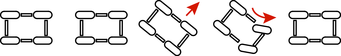
In some situations, the front gearcase may remain locked after turning the AWD switch off. If this occurs, you may notice increased steering effort and some vehicle speed restriction. Perform the following procedure to unlock the front gearcase.
To disengage AWD, do the following:
Stop the vehicle.
Operate in reverse for at least 10 ft (3 m).
Stop completely.
Shift into low gear and drive forward.
If the front gearcase remains locked after following these instructions, see your dealer or other qualified service person for service.
Move the rocker switch to the center position to lock the differential and operate in two wheel drive (2WD). Locking the differential in slippery or low traction conditions helps improve traction. When the rear differential is locked, both rear wheels rotate at the same speed.
When operating in TURF mode, the inside rear wheel will rotate independently from the outside wheel during turns. Operate in TURF mode only as needed to protect smooth, level surfaces from tire damage. DO NOT operate in TURF mode when climbing or descending hills, when sidehilling, or when operating on uneven, loose, or slippery terrain such as sand, gravel, ice, snow, obstacles, and water crossings. Always operate in AWD on these types of terrain.
Press the bottom of the switch to unlock the differential and allow the rear drive wheels to operate independently (1WD). When the rear differential is unlocked, the rear wheels can rotate at different speeds. Unlock the differential to make maneuvering easier and minimize damage to turf.
All riders should wear substantial footwear, long pants and a close-fitting shirt. A hard hat or helmet and approved eye protection are recommended when appropriate for working or riding conditions.
Perform the pre-ride inspection.
Sit in the driver's seat and fasten the seat belt.
Place the transmission in PARK.
Engage the park brake.
Start the engine.
Apply the service brakes and shift the transmission into gear.
Check your surroundings and determine your path of travel.
Release the park brake.
Keeping both hands on the steering wheel, slowly release the brakes and slowly depress the throttle with your right foot to begin driving.
Drive slowly. Practice maneuvering and using the throttle and brakes on level surfaces.
Do not carry a passenger until you have at least two hours of driving experience with this vehicle.
Perform the pre-ride inspection.
Make sure all passengers are at least 12 years of age and tall enough to comfortably and safely sit in a passenger seat with the seat belt secured, put both feet on the floor and grasp the hand hold.
All riders should wear substantial footwear, long pants and a close-fitting shirt. A hard hat or helmet and approved eye protection are recommended when appropriate for working or riding conditions.
Do not carry more than the recommended number of passengers for your vehicle.
Allow a passenger to ride only in a passenger seat.
Slow down. Always travel at a speed appropriate for your skills, your passengers’ skills, and operating conditions. Avoid unexpected or aggressive maneuvers that could cause discomfort or injury to a passenger.
Vehicle handling may change with a passenger and/or cargo on board. Allow more time and distance for braking.
Always follow all operating guidelines as outlined on safety labels and in this manual.
When driving on slippery surfaces such as wet trails, loose gravel, or ice, be alert for the possibility of skidding and sliding. Follow these precautions when encountering slippery conditions:
Do not operate on excessively rough, slippery or loose terrain.
Slow down before entering slippery areas.
Maintain a high level of alertness, reading the trail and avoiding quick, sharp turns, which can cause skids.
Correct a skid by turning the steering wheel in the direction of the skid. Never apply the brakes during a skid.
Whenever traveling uphill, follow these precautions:
Avoid excessively steep hills.
Always travel straight uphill.
Keep both feet on the floor.
Always check the terrain carefully before ascending any hill. Never climb hills with excessively slippery or loose surfaces.
Proceed at a steady rate of speed and throttle opening. Never open the throttle suddenly.
Never go over the crest of a hill at high speed. An obstacle, a sharp drop, or another vehicle or person could be on the other side of the hill.
Driving on a sidehill is not recommended. Improper procedure could cause loss of control or rollover. Avoid crossing the side of any hill unless absolutely necessary.
If crossing a sidehill is unavoidable, follow these precautions:
Slow down.
Exercise extreme caution.
Avoid crossing the side of a steep hill.
When driving downhill, follow these precautions:
Avoid excessively steep hills.
Always descend a hill with the direction selector switch on forward. Never descend a hill with the switch on neutral.
Drive straight downhill. Avoid descending a hill at an angle, which would cause the vehicle to lean sharply to one side. Travel straight downhill when possible.
Slow down.
Apply the brakes slightly to aid in slowing.
Your vehicle can operate through water up to a maximum recommended depth equal to the floorboards.
Follow these procedures when operating through water:
Determine water depths and current before entering water.
Choose a crossing where both banks have gradual inclines.
Proceed slowly, avoiding rocks and obstacles.
Avoid operating through deep or fast-flowing water.
After leaving water, always dry the brakes by applying light pressure to the pedal repeatedly until braking action is normal.
Follow these precautions when operating in reverse:
Always check for obstacles or people behind the vehicle. Always inspect left and right fields of vision before backing.
Always avoid backing downhill.
Back slowly.
Apply the brakes lightly for stopping.
Avoid turning at sharp angles.
Never open the throttle suddenly.
Follow these precautions when operating over obstacles:
Always check for obstacles before operating in a new area.
Look ahead and learn to read the terrain. Be constantly alert for hazards such as logs, rocks and low hanging branches.
Travel slowly and use extra caution when operating on unfamiliar terrain. Not all obstacles are immediately visible.
Avoid operating over large obstacles such as large rocks and fallen trees. If unavoidable, use extreme caution and operate slowly.
Always have all passengers dismount and move away from the vehicle before operating over an obstacle that could cause a rollover.
To park the vehicle, do the following:
Apply the brakes. Stop the vehicle on a level surface.
When parking inside a garage or other structure, be sure that the structure is well ventilated and that the vehicle is not close to any source of flame or sparks, including any appliance with pilot lights.
Place the transmission in PARK.
Turn the engine off.
Engage the park brake.
Slowly release the brake pedal and make sure the transmission is in PARK before exiting the vehicle.
Remove the ignition switch key to prevent unauthorized use.
Avoid parking on an incline if possible. If it's unavoidable, follow these precautions:
Apply the brakes.
Place the transmission in PARK.
Engage the park brake.
Turn the engine off.
Slowly release the brake pedal and make sure the transmission is in PARK before exiting the vehicle.
Block the rear wheels on the downhill side.
Hauling cargo improperly can alter vehicle handling and may cause loss of control or brake instability, which can result in serious injury or death. Always follow these precautions when hauling cargo:
Never exceed the maximum weight capacity of the vehicle. When determining the weight you are adding to the vehicle, include the weight of the operator, passengers, non-factory installed accessories, loads in the rack or box and the load on the trailer tongue. The combined weight of these items must not exceed the maximum weight capacity.
REDUCE SPEED AND ALLOW GREATER DISTANCES FOR BRAKING WHEN HAULING CARGO.
Always load the cargo box with the load as far forward and as low as possible.
When operating over rough or hilly terrain, reduce speed and cargo to maintain stable driving conditions.
Always operate the vehicle with extreme care when hauling or towing loads.
Slow down and drive in the lowest gear available. Always use LOW gear when towing or hauling heavy loads.
SECURE ALL LOADS BEFORE OPERATING. Unsecured loads can create unstable operating conditions, which could result in loss of control of the vehicle.
OPERATE ONLY WITH STABLE AND SAFELY ARRANGED LOADS. When handling off-centered loads that cannot be centered, securely fasten the load and operate with extra caution. Always attach the tow load to the hitch point designated for your vehicle.
HEAVY LOADS CAN CAUSE BRAKING AND CONTROL PROBLEMS. Use extreme caution when applying brakes with a loaded vehicle. Avoid terrain or situations that may require backing downhill.
USE EXTREME CAUTION when operating with loads that extend over the rack sides. Stability and maneuverability may be adversely affected, causing a rollover.
DO NOT TRAVEL FASTER THAN THE RECOMMENDED SPEEDS. Vehicle should never exceed 10 mph (16 kph) while towing a load on a level grass surface. Vehicle speed should never exceed 5 mph (8 kph) when towing loads in rough terrain, while cornering, or while ascending or descending a hill.
Your vehicle has been designed to carry or tow specific capacities. Always read and understand the load distribution warnings listed on the warning labels. The total load (operator, passengers, non-factory installed accessories, cargo and weight on hitch) must not exceed the maximum weight capacity of the vehicle.
Always follow these precautions when towing:
Never load more than 250 lb (113.4 kg) tongue weight on the towing bracket.
When towing a disabled vehicle, place the disabled vehicle’s transmission in neutral. Do not operate the vehicle faster than 10 mph (16 kph) when towing.
Towing a trailer increases braking distance. Do not operate the vehicle faster than 10 mph (16 kph) when towing.
Do not tow more than the recommended weight for the vehicle.
Attach a trailer to the trailer hitch bracket only. Do not attach a trailer to any other location, which could result in loss of control of the vehicle.
The total load (operator, accessories, cargo and weight on hitch) must not exceed the maximum weight capacity of the vehicle.
| MODEL | Total Towed Load Weight (Level Ground) |
Total Towed Load Weight (15° grade) |
Total Hitch Vertical Weight | Maximum Towing Speed |
|---|---|---|---|---|
| Polaris PRO XD |
2500 lb
(1134 kg) |
850 lb
(386 kg) |
250 lb
(113.4 kg) |
10 mph
(16 kph) |
To dump the cargo box, do the following:
Select a level site to dump the cargo box. Do not attempt to dump or unload the vehicle while parked on an incline.
Apply the brakes. Place the transmission in PARK.
Engage the park brake.
Ensure that the cargo is positioned evenly or toward the front of the cargo box.
Release the tailgate by pulling up on the tailgate latch.
Stand clear and pull up on the cargo box release lever 1. Lift the front of the cargo box to dump the cargo.
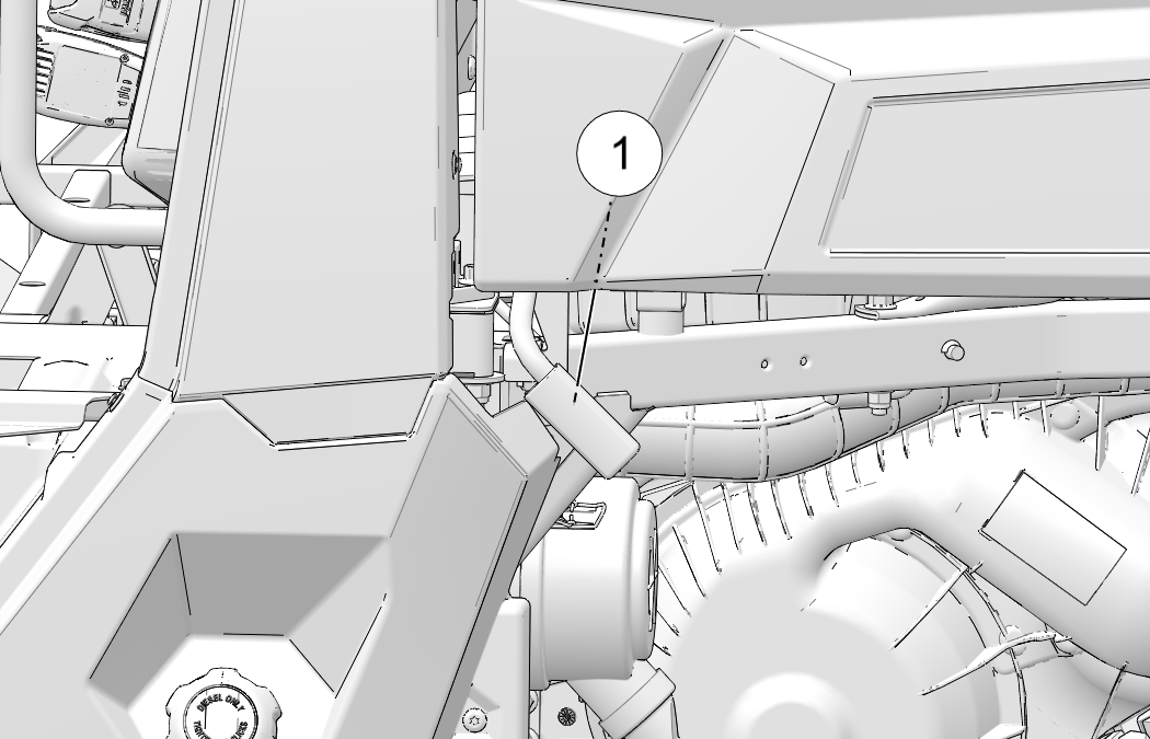
Lower the cargo box and push down securely to latch.
These safety warnings and instructions apply if your vehicle came equipped with a winch or if you choose to add an accessory winch to your vehicle.
Your winch may have a cable made of either wire rope or specially designed synthetic rope. The term “winch cable” will be used for either unless noted otherwise.
Read all sections of this manual.
Never use alcohol or drugs before or while operating the winch.
Never allow children under 16 years of age to operate the winch.
Always wear eye protection and heavy gloves when operating the winch.
Always keep body, hair, clothing and jewelry clear of the winch cable, fairlead and hook when operating winch.
Never attempt to “jerk” a load attached to the winch with a moving vehicle. See the Shock Loading section on Shock Loading.
Always keep the area around the vehicle, winch, winch cable, and load clear of people (especially children) and distractions while operating the winch.
Always turn the vehicle ignition power OFF when it and the winch are not being used.
Always be sure that at least five (5) full turns of winch cable are wrapped around the winch drum at all times. The friction provided by this wrapped cable allows the drum to pull on the winch cable and move the load.
Always apply your vehicle’s park brake and/or park mechanism to hold the vehicle in place during winching. Use wheel chocks if needed.
Always align the vehicle and winch with the load directly in front of the vehicle as much as possible. Avoid winching with the winch cable at an angle to the winching vehicle’s centerline whenever possible.
If winching at an angle is unavoidable, follow these precautions:
Look at the winch drum occasionally. Never let the winch cable “stack” or accumulate at one end of the winch drum. Too much winch cable at one end of the winch drum can damage the winch and the winch cable.
If stacking occurs, stop winching. Follow step 15 of Winch Operation to feed and rewind the cable evenly before continuing the winch operation.
Never winch up or down at sharp angles. This can destabilize the winching vehicle and possibly cause it to move without warning.
Never attempt to winch loads that weigh more than the winch’s rated capacity.
The winch motor may become hot during winch use. If you winch for more than 45 seconds, or if the winch stalls during operation, stop winching and permit the winch to cool down for 10 minutes before using it again.
Never touch, push, pull or straddle the winch cable while winching a load.
Never let the winch cable run through your hands, even if wearing heavy gloves.
Never release the clutch on the winch when the winch cable is under load.
Never use the winch for lifting or transporting people.
Never use the winch to hoist or suspend a vertical load.
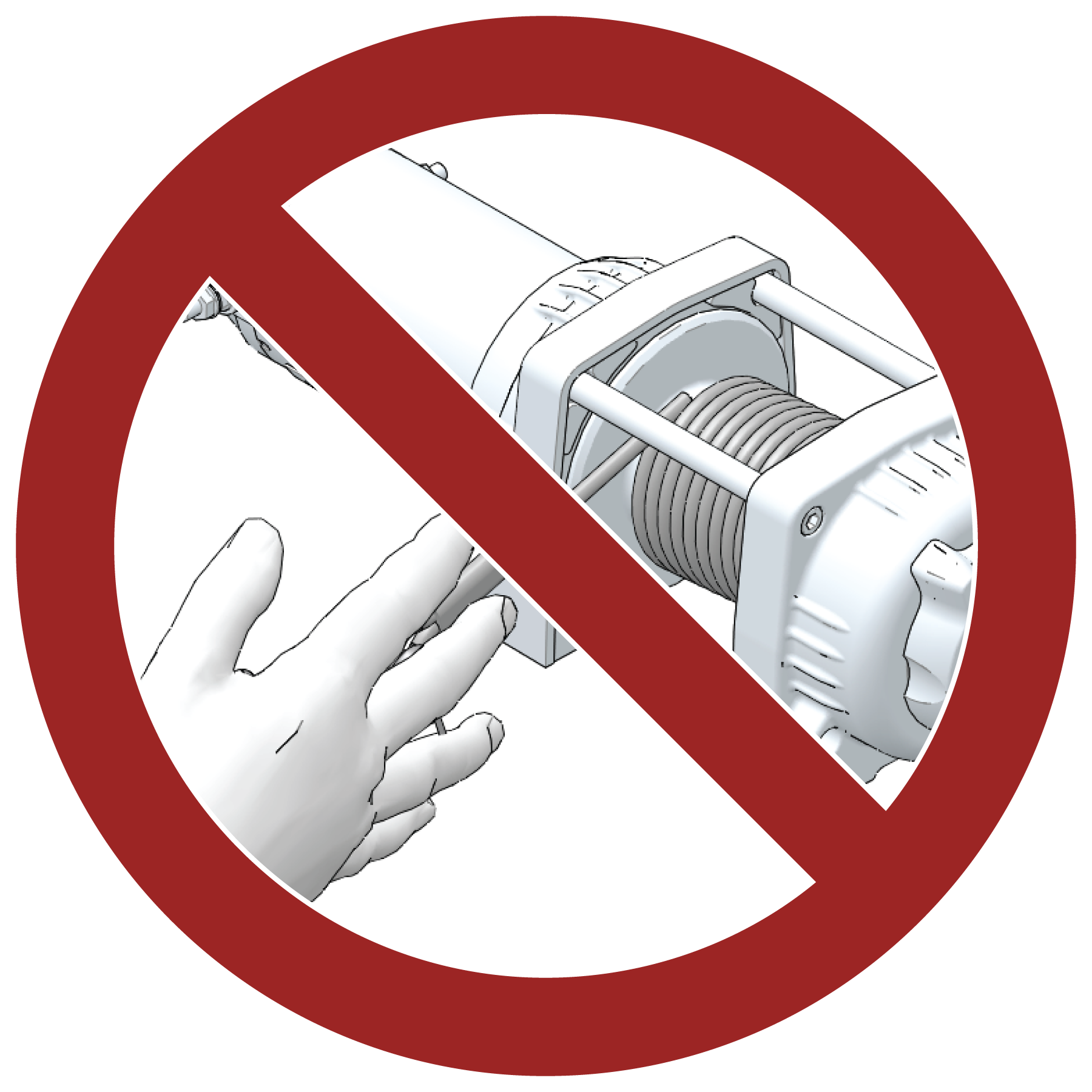
Always inspect your winch and winch cable before each use.
Never winch the hook fully into the winch. This can cause damage to winch components.
Unplug the remote control from the vehicle when the winch is not in use to prevent inadvertent activation and use by unauthorized persons.
Never grease or oil the winch cable. This will cause the winch cable to collect debris that will shorten the life of the cable.
Read the Winch Safety Precautions in the preceding pages before using your winch.
Consider practicing the operation and use of your winch before you actually need to use it in the field.
Improper winch use can result in SEVERE INJURY or DEATH. Always follow all winch instructions and warnings in this manual.
Each winching situation is unique.
Take your time to think through the winching you are about to do.
Proceed slowly and deliberately.
Never hurry or rush during winching.
Always pay attention to your surroundings.
You may need to change your winching strategy if it is not working.
Always remember that your winch is very powerful.
There are simply some situations that you and your winch will not be able to deal with. Do not be afraid to ask others to help when this happens.
Always inspect the vehicle, winch, winch cable and winch controls for any signs of damage or parts in need of repair or replacement before each use. Pay particular attention to the first 3 feet (1 meter) of winch cable if the winch is being used (or has been used) for lifting an accessory plow assembly. Promptly replace any worn or damaged cable.
Never operate a winch or a vehicle in need of repair or service.
Always apply your vehicle’s park brake and/ or park mechanism to hold the vehicle in place during winching. Use wheel chocks if needed.
Always use the hook strap when handling the hook.
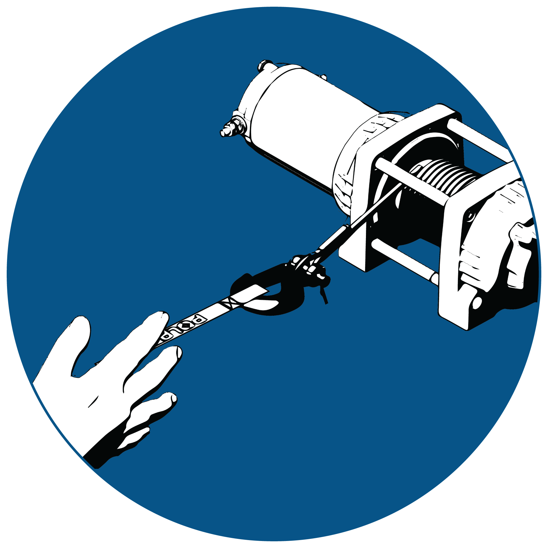
Never put your fingers into the hook. This could lead to SEVERE INJURY.
Attach the hook itself onto the load or use a tow strap or chain to secure the load to the winch cable.

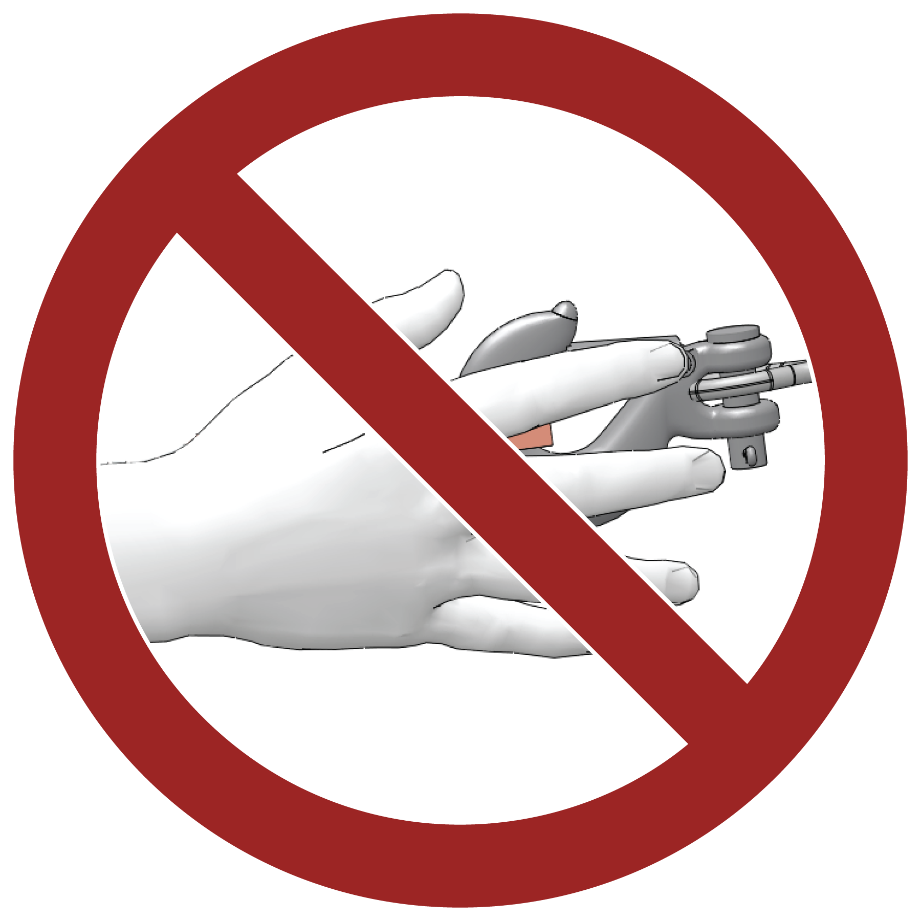
A “tow strap” is NOT intended to stretch. A “recovery strap” is designed to stretch.
Never hook the winch cable back onto itself. This will damage the winch cable and may result in winch cable failure.
If possible, keep the winch cable aligned with the centerline of the winching vehicle. This will help the spooling of the winch cable and reduce the load on the fairlead.
If freeing a stuck vehicle by attaching to a tree, use an item such as a tow strap to avoid damaging the tree during winch operation. Sharp cables and chains can damage and even kill trees. Please remember to Tread Lightly℠ (treadlightly.org).
Before operating the winch, be sure that the safety latch on the winch cable hook is fully seated when the load is attached.
Never operate your winch with a damaged hook or latch. Always replace damaged parts before using the winch.
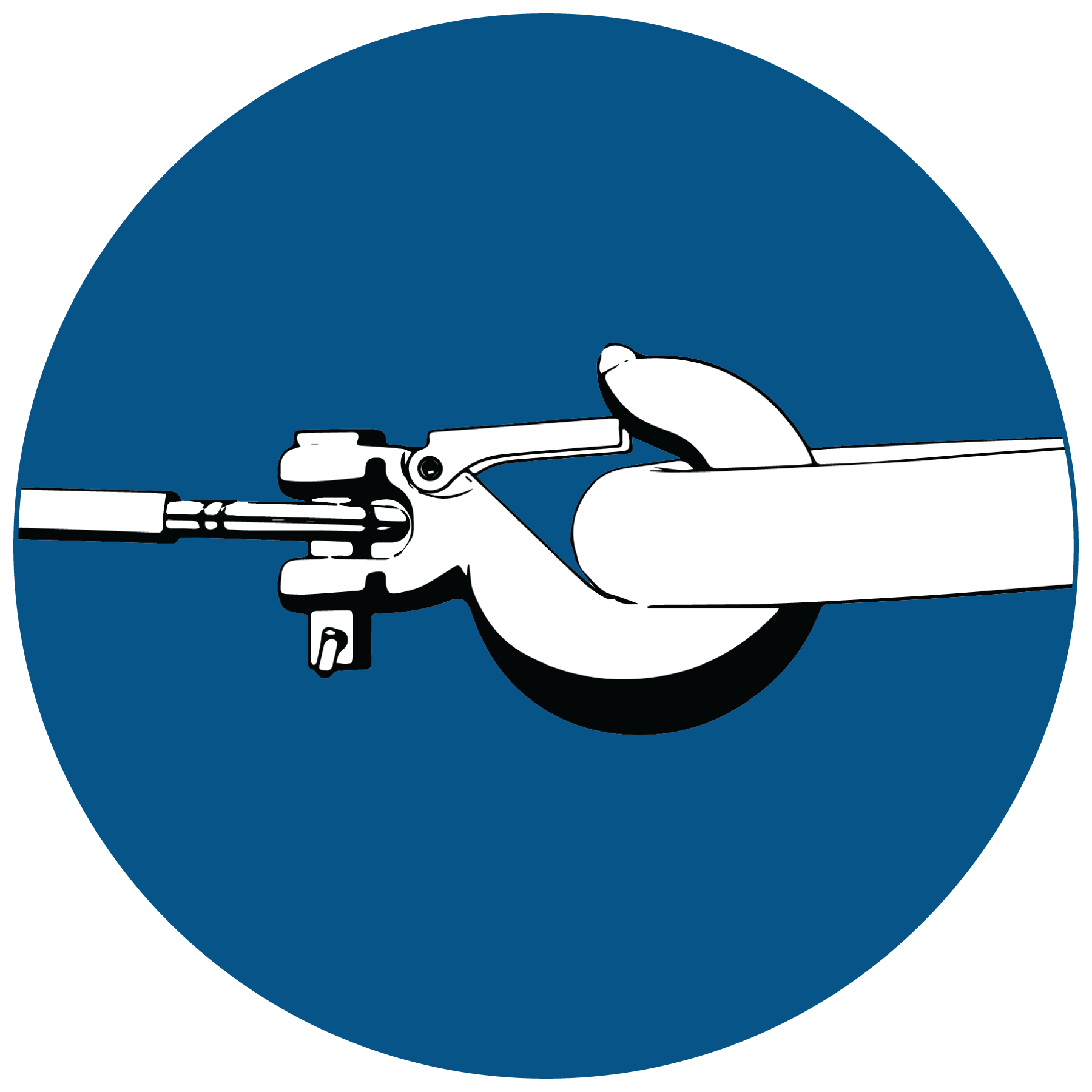
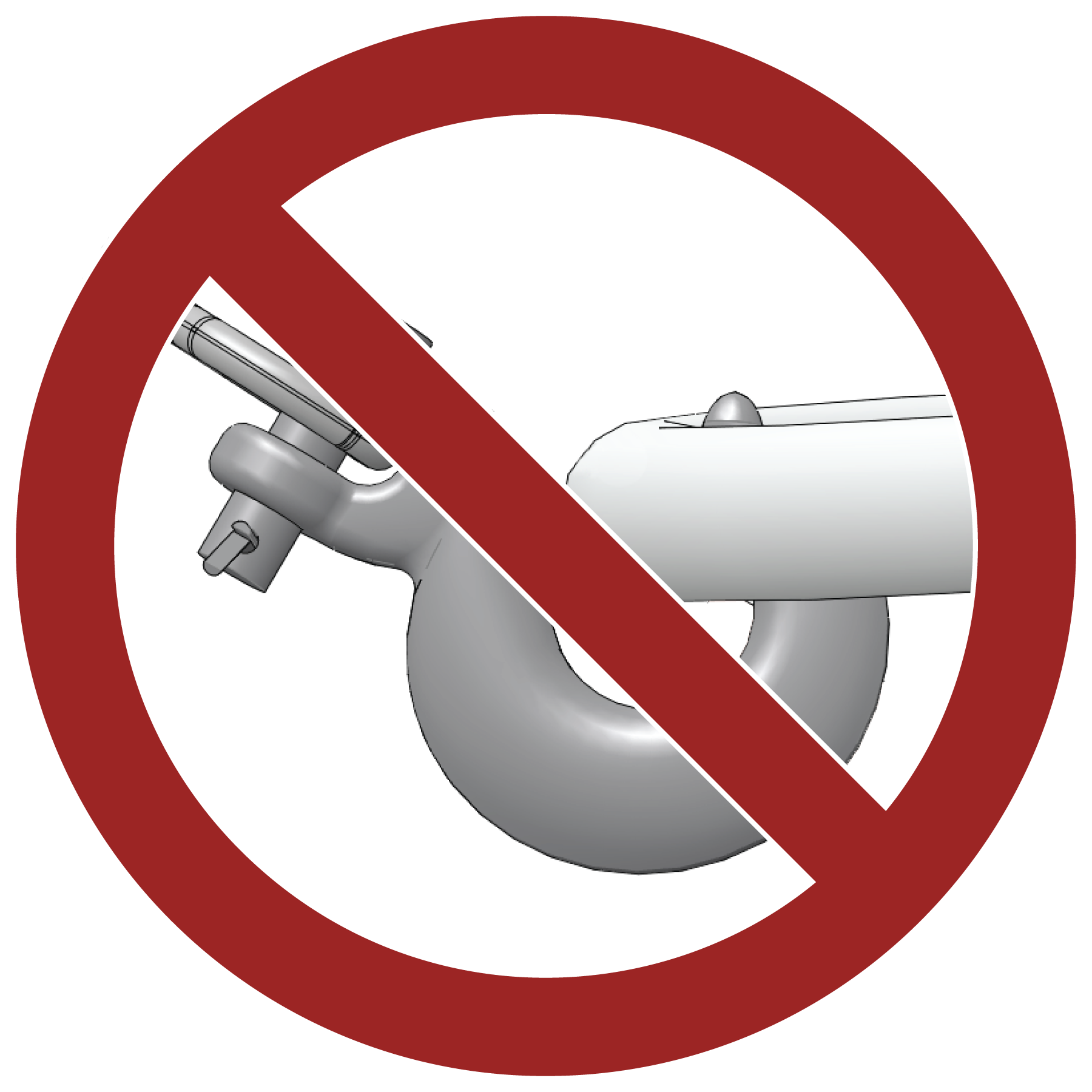
Never remove the hook strap from the hook.
Release the winch clutch and pull out the winch cable.
Pulling out as much cable as possible maximizes the winch’s pulling capacity. Always be sure that at least five (5) full turns of winch cable are wrapped around the winch drum at all times. The friction provided by this wrapped cable allows the drum to pull on the winch cable and move the load.
Read and adhere to the following information for winch damping to ensure safe winch use.
In order to absorb energy that could be released by a winch cable failure, always place a “damper” on the winch cable. A damper can be heavy jacket, tarp, or other soft, dense object. A damper can absorb much of the energy released if a winch cable breaks when winching. Even a tree limb can help as a damper if no other items are available to you.
Lay the damper on top of the mid-point of the winch cable length that is spooled out.
On a long pull, it may be necessary to stop winching so that the damper can be repositioned to the new mid-point of the winch cable. Always release the tension on the winch cable before repositioning the damper.
Avoid being directly in line with the winch cable whenever possible. Also, never permit others to stand near or in line with the winch cable during winch operation.
Never hook the winch cable back onto itself. This will damage the winch cable and may result in winch cable failure.
Never use straps, chains or other rigging items that are damaged or worn.
The ONLY time a winch-equipped vehicle should be moving when using the winch is when that vehicle itself is stuck. The winch equipped vehicle should NEVER be in motion to “shock” load the winch cable in an attempt to move a second stuck vehicle. See the Shock Loading section on Shock Loading. For your safety, always follow these guidelines when winching a vehicle free:
Release the winch clutch and spool out the necessary length of winch cable.
Align the winch cable as close as possible to the winching vehicle’s centerline.
Attach the winch cable hook to the anchor point or the stuck vehicle’s frame following instructions in this manual.
Re-engage the clutch on the winch.
Slowly winch in the slack in the winch cable.
Select the proper vehicle gear to propel the stuck vehicle in the direction of winching.
Shift to the lowest gear available on the stuck vehicle.
Slowly and carefully apply vehicle throttle and winch together to free the vehicle.
Stop winching as soon as the stuck vehicle is able to propel itself without the help of the winch.
Detach the winch cable hook.
Rewind the winch cable evenly back onto the winch drum following the instructions in this manual.
Never attempt to winch another stuck vehicle by attaching the winch cable to a suspension component, brush guard, bumper or cargo rack. Vehicle damage may result. Instead, attach the winch to a strong portion of the vehicle frame or hitch.
Extensive winching will run down the battery on the winching vehicle. Let the winching vehicle’s engine run while operating the winch to prevent the battery from running low if winching for long periods.
The winch motor may become hot during winch use. If you winch for more than 45 seconds, or if the winch stalls during operation, stop winching and permit the winch to cool down for 10 minutes before using it again.
After winching is complete, especially if winching at an angle, it may be necessary to re-distribute the winch cable across the winch drum. You will need an assistant to perform this task.
Release the clutch on the winch.
Feed out the winch cable that is unevenly bunched up in one area.
Re-engage the winch clutch.
Have an assistant pull the winch cable tightly with about 100 lbs. (45 kg) of tension using the hook strap.
Slowly winch the cable in while your assistant moves the end of the winch cable back and forth horizontally to evenly distribute the winch cable on the drum.
Doing this reduces the chances of the winch cable “wedging” itself between lower layers of winch cable.
Use of worn or damaged cable could lead to sudden failure and SEVERE INJURY.
For your safety, always replace POLARIS winch parts (including the cable) with genuine POLARIS replacement parts available at your authorized POLARIS dealer, or other qualified person.
Always inspect your winch before each use. Inspect for worn or loose parts including mounting hardware. Never use the winch if any part needs repair or replacement.
Always inspect your winch cable before each use. Inspect for worn or kinked winch cable.
A kinked winch cable made of wire rope is shown at right. Even after being “straightened out,” this cable has already been permanently and severely damaged. Promptly discontinue use of a winch cable in this condition.
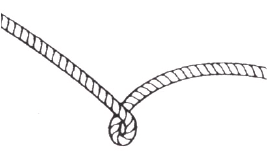
A kinked winch cable made of wire rope that has been “straightened out” is shown at right. Even though it may look usable, the cable has been permanently and severely damaged. It can no longer transmit the load that it could prior to kinking. Promptly discontinue use of a winch cable in this condition.
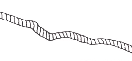
A winch cable made of synthetic rope should be inspected for signs of fraying. Replace the cable if fraying is observed (shown below). Promptly discontinue use of a winch cable in this condition. Also replace the winch cable if there are fused or melted fibers. Such an area of the synthetic rope will be stiff and appear smooth or glazed. Promptly discontinue use of a winch cable in this condition.
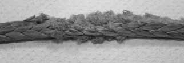
Your winch cable is very strong but it is NOT designed for dynamic, or “shock” loading. Shock loading may tension a winch cable beyond its strength and cause the cable to break. The end of a broken winch cable under such high loading can cause SEVERE INJURY or DEATH to you and other bystanders.
Winch cables are designed to NOT absorb energy. This is true of both wire-rope and synthetic-rope winch cables.
Never attempt to “jerk” a load with the winch. For example, never take up slack in the winch cable by moving the winching vehicle in an attempt to move an object. This is a dangerous practice. It generates high winch cable loads that may exceed the strength of the cable. Even a slowly moving vehicle can create large shock loads in a winch cable.
SEVERE INJURY or DEATH can result from a broken winch cable.
Never quickly turn the winch ON and OFF repeatedly (“jogging”). This puts extra load on the winch, winch cable, and generates excessive heat from the motor. This is a form of shock loading.
Never tow a vehicle or other object with your winch. Towing an object with a winch produces shock loading of the cable even when towing at slow speeds. Towing from a winch also positions the towing force high on the vehicle. This can cause instability of the vehicle and possibly lead to an accident.
Never use recovery straps with your winch. Recovery straps are designed to stretch and can store energy. This stored energy in the recovery strap is released if a winch cable fails making the event even more hazardous. Similarly, never use elastic “bungie” cords for winching.
Never use the winch to tie down a vehicle to a trailer or other transportation vehicle. This type of use also causes shock loading that can cause damage to the winch, winch cable, or vehicles used.
Your winch cable is designed and tested to withstand the loads produced by the winch motor when operated from a stationary vehicle. Always remember that the winch and winch cable are NOT designed for shock loading.
Always inspect your winch before each use. Inspect for worn or kinked winch cable. Also inspect for worn or loose parts including mounting hardware.
Permit your winch motor to cool down prior to servicing your winch.
Never work on your winch without first disconnecting the battery connections to prevent accidental activation of the winch.
For your safety, always replace POLARIS winch parts (including the cable) with genuine POLARIS replacement parts available at your authorized POLARIS dealer, or other qualified person.
Some winch models use wire rope as the winch cable. Other winches use a specially designed synthetic rope as the winch cable.
Never replace a synthetic-rope winch cable with a consumer-grade polymer rope such as can be purchased in a hardware store. Although they may look similar, they are NOT alike. A polymer rope not designed for winch use will stretch and store excessive energy when winching.
Do not modify the engine, intake or exhaust components, as doing so may affect compliance with U.S.A. EPA noise control requirements (40 CFR 205) and local noise level requirements.
Your vehicle has a spark arrester that was tested and qualified to be in accordance with the USFS standard 5100-1a. Federal law requires that this spark arrester be installed and functional when the vehicle is operated on public lands.
Operation of off-road vehicles on public lands in the U.S.A. is regulated by 43 CFR 420. Violations are subject to monetary penalties. Federal regulations can be viewed online at https://ecfr.federalregister.gov/current/title-43/subtitle-B/chapter-I/part-420.
Exhaust emissions are controlled by engine design. A fuel injection system controls fuel delivery. The engine and fuel injection components are set at the factory for optimal performance and are not adjustable.
Your engine is designed to operate on ultra low sulfur diesel fuel only. Use of any other fuel may result in your engine no longer operating in compliance with emissions requirements.
CAN ICES-2/NMB-2
This diesel vehicle complies with
Canada ICES-002.
This vehicle complies with the EMC requirements of UN ECE Regulation 10.
Non-ionizing Radiation: This vehicle emits some electromagnetic energy. People with active or non-active implantable medical devices (such as heart monitoring or controlling devices) should review the limitations of their device and the applicable electromagnetic standards and directives that apply to this vehicle.
Any qualified repair shop or person may maintain, replace or repair the emission control devices or systems on your vehicle. An authorized POLARIS dealer can perform any service that may be necessary for your vehicle. POLARIS also recommends POLARIS parts for emissions-related service, however equivalent parts may be used for such service.
It is a potential violation of the Clean Air Act if a part supplied by an aftermarket parts manufacturer reduces the effectiveness of the vehicle’s emission controls. Tampering with emission controls is prohibited by federal law.
Owners are responsible for performing the scheduled maintenance identified in this owner’s manual.
Careful periodic maintenance will help keep your vehicle in the safest, most reliable condition. Inspection, adjustment and lubrication of important components are explained in the periodic maintenance chart.
Inspect, clean, lubricate, adjust and replace parts as necessary. When inspection reveals the need for replacement parts, genuine POLARIS parts are available from your POLARIS dealer.
Record maintenance and service in the Maintenance Log at the end of the manual.
Vehicles subjected to heavy or severe use patterns must be inspected and serviced more frequently.
Frequent immersion in mud, water or sand
Prolonged low speed, heavy load operation
The break-in period consists of the first 50 hours of operation. Careful treatment of a new engine and drive components will result in more efficient performance and longer life for these components.
Drive vehicle slowly at first while varying the throttle position. Do not operate at sustained idle.
Perform regular checks on fluid levels and other areas outlined on the daily pre-ride inspection checklist.
Change both the engine oil and filter after 50 hours or one month.
The maintenance interval charts list required maintenance and inspection based on vehicle hours / miles. Each table states a service that corresponds to the hour / mile chart below. Some items or components may need to be serviced more often due to severe use, such as operation in water, extreme temperatures, or under severe loads.
| Hour / Mileage | Service |
|---|---|
| First 50 hours / 500 mi (800 km) | Break-In Service — Perform the 200 Hour Check List (Table 2) |
| Every 50 hours / 500 mi (800 km) thereafter | See Table 1 |
| Every 200 hours / 2000 mi (3200 km) thereafter | See Table 2 |
| Service Codes |
|---|
|
XU - PERFORM THESE PROCEDURES MORE OFTEN FOR VEHICLES SUBJECTED TO SEVERE USE. D - HAVE AN AUTHORIZED POLARIS DEALER OR OTHER QUALIFIED PERSON PERFORM THESE SERVICES. E - EMISSION CONTROL SYSTEM SERVICE (CALIFORNIA). |
|
Break-In Service
First 50 Hours / 500 mi (800 km) |
||
|---|---|---|
| Perform the 200 Hour Checklist (Table 2) for Break-In Service |
|
TABLE 1. EVERY 50 HOURS / 500 mi (800 km) SERVICE |
||
|---|---|---|
| CODE | ITEM | ACTION |
|
XU / E |
Engine Oil & Filter Change |
Inspect oil level (Break-in oil and filter change at first 50 hrs; perform every 200 hrs, thereafter) |
|
XU |
Brake Pads / Parking Brake Pads |
Inspect pad wear; contact dealer to replace if worn beyond service limit |
|
E |
Fuel System |
Turn key on to pressurize fuel pump; check lines and fittings for leaks and abrasion, contact dealer for repairs |
|
XU |
Parking Brake |
Inspect operation; contact dealer to adjust tension as needed |
|
|
Battery |
Check terminals; clean if necessary |
|
|
Fan/Alternator Belt |
Inspect belt quality and tension- Adjust/replace as necessary |
|
XU |
Front Gearcase Lubricant |
Inspect / add lubricant if needed |
|
XU |
Transmission Lubricant (AGL) |
Inspect / add lubricant if needed |
|
E |
Throttle Pedal / Throttle Linkage |
Inspect for proper operation and smooth travel; contact dealer if any concerns are found |
|
XU |
Air Filter / Air Box |
Inspect; replace filter as needed, or yearly (Item part of Pre-Ride Inspection) |
|
E |
Air Intake Ducts / Adapters |
Inspect ducts for proper sealing, and ensure clamps are tight; contact dealer for any repairs |
|
|
Shift Cable / Linkage |
Inspect; Contact dealer to adjust as needed, |
|
|
Steering |
Inspect for loose components and torn boots; contact dealer to replace parts as needed |
|
XU |
Rear Stabilizer Bar |
Lubricate and inspect bushings |
|
XU |
Radiator |
Inspect; clean external surfaces |
|
E |
Fuel Filter / Water Separator |
Drain every 50 hrs (normal conditions with quality fuel) or daily (severe conditions with poor fuel quality) |
|
XU |
Axles |
Inspect boots for damage |
|
TABLE 2. EVERY 200 HOURS / 2000 mi (3200 km) SERVICE |
||
|---|---|---|
| CODE | ITEM | ACTION |
|
XU / E |
Engine Oil & Filter Change |
Perform a break-in oil and filter change at first 50 hrs; perform every 200 hrs thereafter |
|
XU / D |
Brake Pads / Parking Brake Pads |
Inspect pad wear; replace if worn beyond service limit |
|
D / E |
Fuel System |
Turn key on to pressurize fuel pump; check lines and fittings for leaks and abrasion,Check for leaks at fill cap, and fuel pump. |
|
XU / D |
Parking Brake |
Inspect operation; adjust tension as needed |
|
Battery |
Check terminals; clean; test |
|
|
E |
Throttle Pedal / Throttle Linkage |
Inspect for proper operation and smooth travel; contact dealer if any concerns are found |
|
E |
Air Intake Ducts/Adapters |
Inspect ducts for proper sealing, and ensure clamps are tight; contact dealer for any repairs |
|
XU |
Air Filter / Air Box |
Replace filter (Item part of Pre-Ride Inspection) |
|
Shift Cable / Linkage |
Inspect; adjust as needed |
|
|
D |
Steering |
Inspect for loose components and torn boots; replace parts as needed |
|
Fan/Alternator Belt |
Inspect belt quality and tension- Adjust/replace as necessary |
|
|
D |
Cooling System |
Inspect coolant strength; pressure test system Replace coolant every 5 years. |
|
D |
Drive Belt |
Inspect; replace as needed |
|
XU |
Front Gearcase Lubricant |
Change lubricant |
|
XU |
Transmission Lubricant (AGL) |
Change lubricant |
|
E |
Fuel Filter / Water Separator |
Replace filter |
|
XU |
Radiator |
Inspect; clean external surfaces |
|
XU |
Cooling Hoses |
Inspect for leaks; pressure test system |
|
XU / D |
Engine Mounts |
Inspect, torque to specification |
|
Exhaust Silencer / Pipe |
Inspect |
|
|
XU |
Wiring |
Inspect for wear, routing, security; inspect connectors subjected to water, mud, etc. |
|
D |
Clutches (Drive and Driven) |
Inspect; clean; replace worn parts |
|
D |
Wheel Bearings |
Inspect; replace as needed |
|
Tires / Wheels |
Inspect tire tread; rotate as needed |
|
|
XU |
Shocks |
Visually inspect shock seals, replace as necessary |
|
D |
Brake Fluid |
Inspect level and quality, Change fluid every 2 years (DOT 4) |
|
D |
Front Wheel Alignment |
Inspect toe alignment, and adjust if necessary |
|
XU |
Suspension Bushings |
Inspect front and rear suspension bushings; replace if necessary |
|
XU |
Rear Stabilizer Bar |
Lubricate grease zerks and inspect bushings |
|
XU |
Prop Shafts |
Lubricate grease zerks |
|
XU |
Axles |
Inspect boots for damage |
Check and lubricate all components at the intervals outlined in the Periodic Maintenance Chart, or more often under severe use, such as wet or dusty conditions. Items not listed in the chart should be lubricated at the general lubrication interval.
| Item | Lube | Method |
|---|---|---|
| Engine Oil | POLARIS Diesel Oil See Oil Recommendations | Add to proper level on dipstick. See Oil Check. |
| Brake Fluid | DOT 4 Brake Fluid | Maintain level between fill lines. See Brakes. |
| Transmission Oil (Main Gearcase) |
AGL Gearcase Lubricant & Transmission Fluid | See Transmission Oil Check. |
| Demand Drive Fluid (Front Gearcase) |
Demand Drive Fluid | See Demand Drive Oil Check. |
| Prop Shaft | U-Joint Grease | Locate fittings and grease. |
Always check and change the oil at the intervals outlined in the Periodic Maintenance Chart. Always use the recommended engine oil. Always change the oil filter whenever changing oil.
Vehicle operation with insufficient, deteriorated, or contaminated engine oil will cause accelerated wear and may result in engine seizure, accident and injury. Always perform the maintenance procedures as outlined in the Periodic Maintenance Chart.
POLARIS recommends the use of POLARIS Diesel Oil for this vehicle. Always use the correct viscosity grade based on the ambient temperature expected during operation. See the chart below.
|
SAE 5W-40 |
|||
|
SAE 15W-40 |
|||
|
-25 f (-31 c) |
+5 f (-15 c) |
+80 f (+27 c) |
+104 f (+40 c) |
This engine has a wet-sump design, meaning the engine oil is contained in the bottom of the crankcase. To check the oil level, follow the procedure listed below:
Check the oil when the engine is cold and safe to touch.
Make sure that the vehicle is on a level surface and that the transmission in PARK.
Locate the dipstick 1 on the right side of the unit.
Remove the dipstick and wipe it dry with a clean cloth.
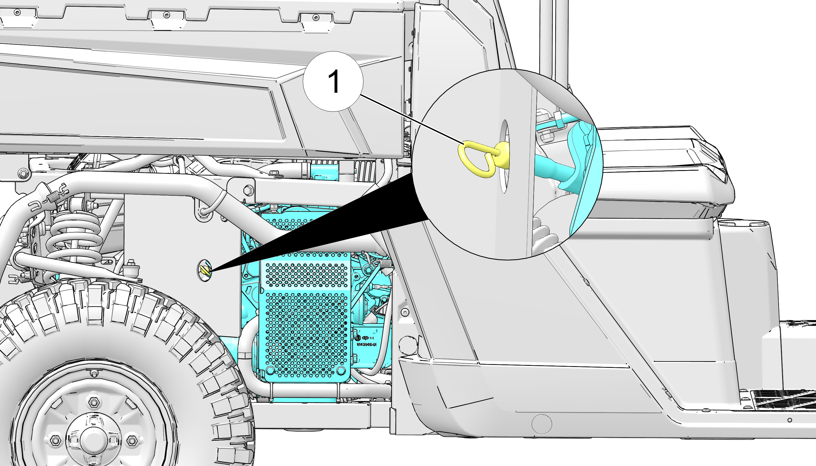
Reinstall the dipstick and push it into place.
Make certain the dipstick is inserted all the way into the dipstick tube to keep the depth of the dipstick consistent.
Remove the dipstick and check the oil level.
Add the recommended oil as necessary to bring the oil level within the SAFE range on dipstick. Do not overfill.
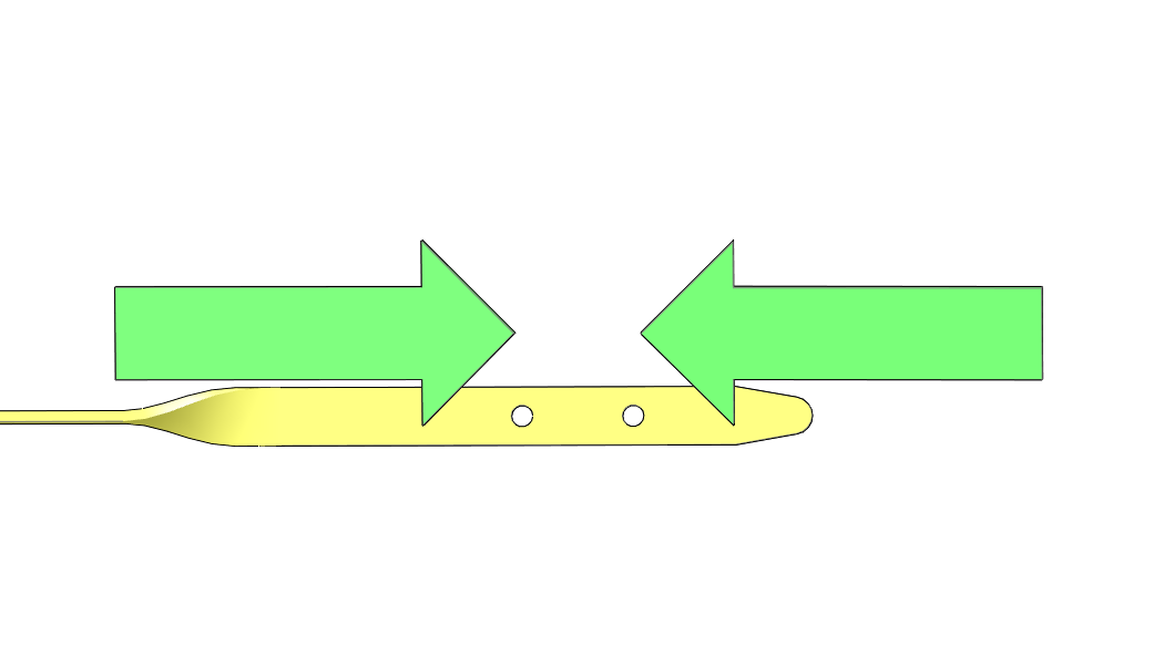
A rising oil level between checks during cold weather operation can indicate contaminants such as gas or moisture collecting in the crankcase. If the oil level is over the upper mark, change the oil immediately.
With the cargo box raised, add engine oil through the oil fill cap 2 located on top of the valve cover, under the cargo box.

When finished, reinstall dipstick. Lower the cargo box and secure in position.
Check around and under the engine for oil leaks.
Always change engine oil and filter at the intervals outlined in the Periodic Maintenance Chart. Always change the oil filter whenever changing the engine oil.
The engine oil dipstick is located on the right front side of the engine. The engine oil fill cap is located on top of the valve cover. Access the oil fill cap by tilting the rear cargo box.
The crankcase drain plug is located on the bottom of the crankcase. Access the drain plug through the skid plate access hole located directly under the crankcase.
Position vehicle on a level surface and place the transmission in PARK.
Stop the engine and allow it to cool down.
Clean the area around the crankcase drain plug.
Use caution when performing this procedure. Do not allow hot engine oil to come into contact with skin, as serious burns may result.
Place a drain pan under the engine crankcase and remove the drain plug 1. Allow the oil to drain completely.

Using an oil filter wrench, turn the oil filter 2 counter-clockwise to remove it.
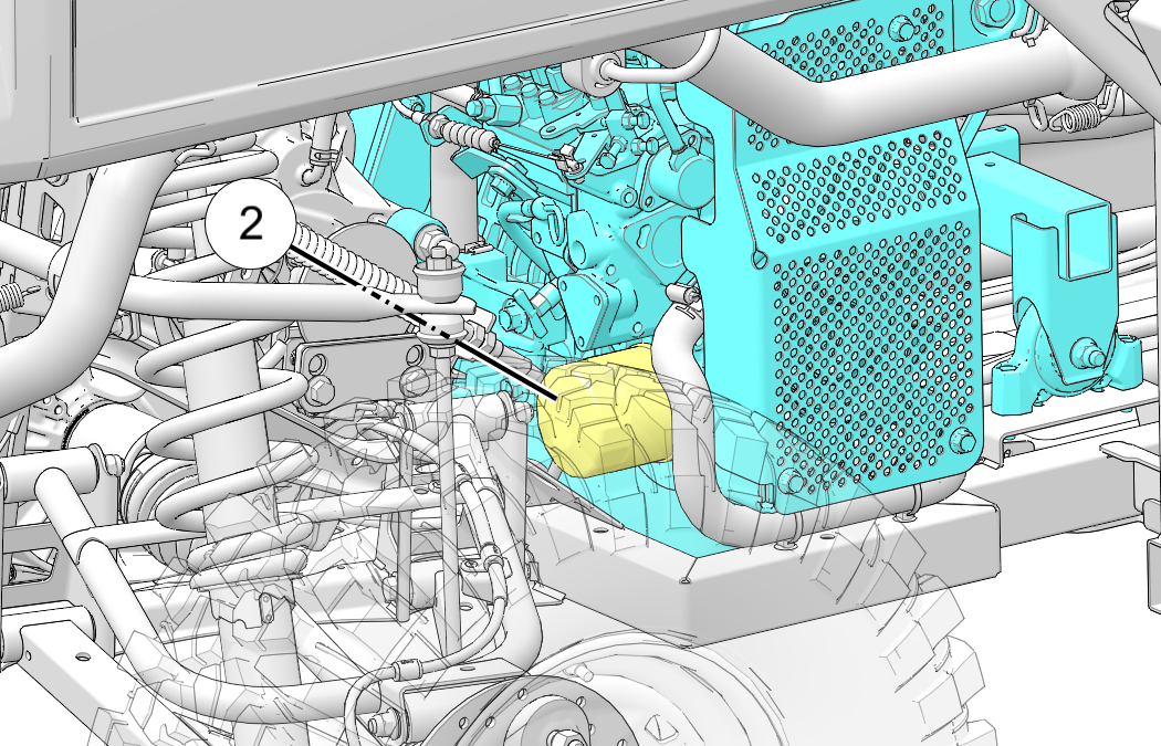
Using a clean dry cloth, clean the filter sealing surface on the engine crankcase.
Lubricate the O-ring on the new oil filter with a film of fresh engine oil. Check to make sure the O-ring is in good condition.
Install the new filter and turn by hand until the filter O-ring contacts the sealing surface, then turn an additional 3/4 turn
Replace the sealing washer on drain plug.
The sealing surface on the drain plug should be clean and free of burrs, nicks or scratches.
Reinstall the engine crankcase drain plug. Torque the drain plug to 12 ft-lbs (16 N·m).
Remove all cargo from the cargo box.
Always remove all cargo from the cargo box before lifting the box to access the engine.
Pull up on the cargo box release lever to tilt the box.
Remove oil fill cap and add 3.9 qt (3.7 l) of recommended oil. Reinstall the fill cap.
Verify the transmission is still in PARK.
Start the engine and allow it to idle for 30 seconds.
Stop the engine and inspect for oil leaks. Wait at least 15 seconds before removing the dipstick.
Remove the dipstick and wipe it dry with a clean cloth.
Reinstall the dipstick and push it into place.
Make certain the dipstick is inserted all the way into the dipstick tube to keep the depth of the dipstick consistent.
Remove the dipstick and check the oil level.
Add the recommended oil as necessary to bring the oil level within the SAFE range on dipstick. Do not overfill.
When finished, reinstall the oil fill cap and oil dipstick.
Dispose of used oil and filter properly.
|
Gearcase |
Lubricant |
Capacity |
Fill Plug Torque |
Drain Plug/ Level Check Plug Torque |
|---|---|---|---|---|
|
Transmission (Main Gearcase) |
AGL Gearcase Lubricant & Transmission Fluid |
41 floz (1200 ml) |
10–14 ft-lbs (14–19 N·m) |
10–14 ft-lbs (14–19 N·m) |
|
Demand Drive Unit (Front Gearcase) |
Demand Drive Fluid |
9.3 floz (275 ml) |
8–10 ft-lbs (11–14 N·m) |
11 ft-lbs (15 N·m) |
Always check and change the transmission oil at the intervals outlined in the Periodic Maintenance Chart. Maintain the oil level even with the bottom thread of the fill plug hole.
The fill plug is located on the rear of the gearcase. Maintain the fluid level at the bottom of the fill plug hole.
To check the transmission fluid, do the following:
Position the vehicle on a level surface.
Remove the fill plug 1.
Check the fluid level.
Add the recommended fluid to the bottom of the fill plug hole. Do not overfill.
Reinstall the fill plug. Torque to specification.
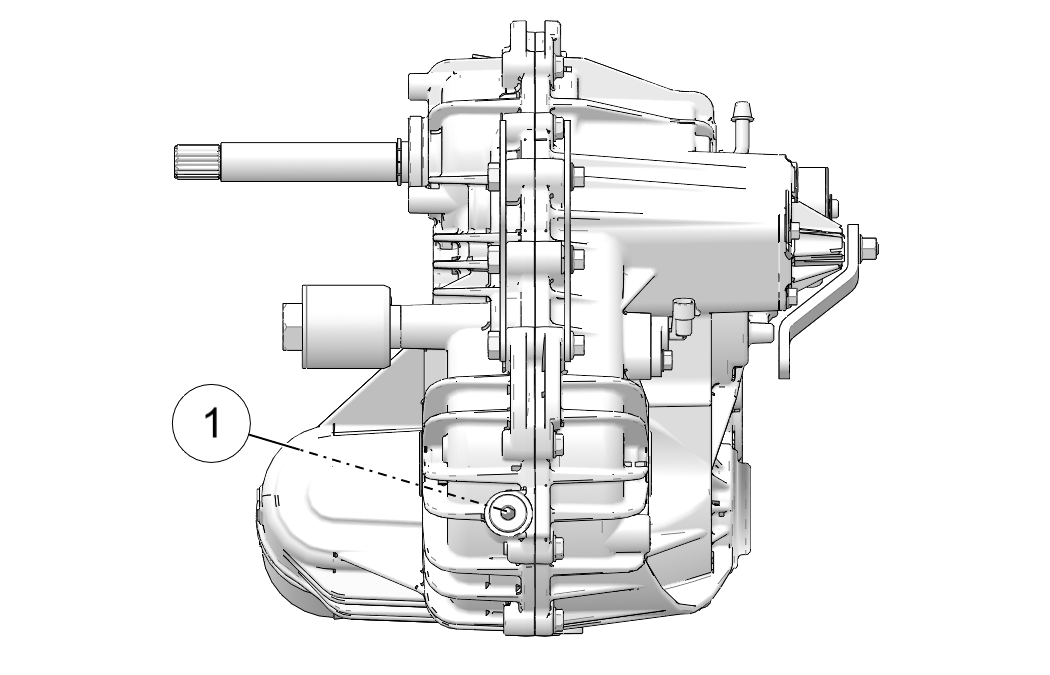
The drain plug is located on the bottom of the gearcase. Access the drain plug through the hole in the skid plate.
Remove the fill plug 1.
Place a drain pan under the drain plug 2.
Remove the drain plug. Allow the fluid to drain completely.
Clean and reinstall the drain plug. Torque to specification.
Add the recommended fluid to the bottom of the fill plug hole. Do not overfill.
Reinstall the fill plug. Torque to specification.
Check for leaks. Discard used fluid properly.
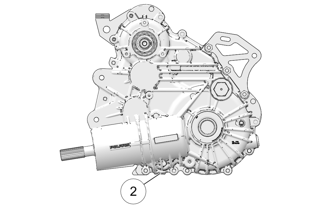
Always check and change the demand drive fluid at the intervals outlined in the Periodic Maintenance Chart. Maintain the oil level even with the bottom thread of the fill plug hole. Refer to the Gearcase Specifications Chart for recommended lubricants, capacities and torque specifications.
The front gearcase fill plug 1 is located on the right side of the front gearcase.
Position the vehicle on a level surface.
Remove the fill plug 1. Check the oil level.
Add the recommended oil as needed.
Reinstall the fill plug. Torque to specification.
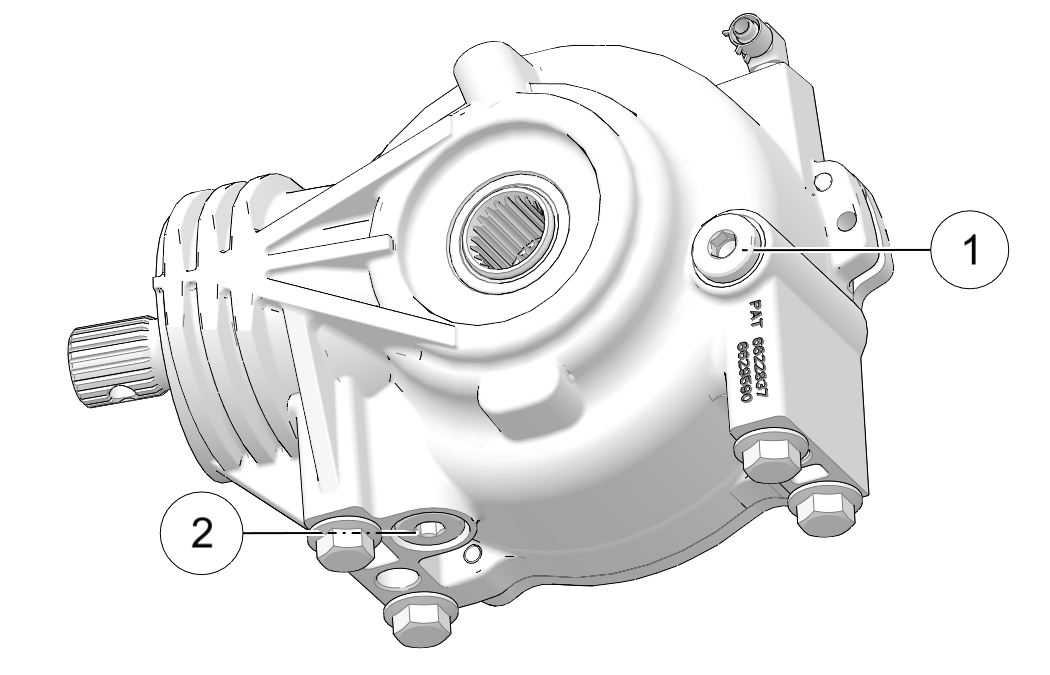
Support the vehicle securely with a jackstand.
Remove the front tire on the passenger's side for ease of access (optional).
Remove the fill plug.
Place a drain pan under the drain plug 2 on the bottom right-hand side.
Remove the drain plug. Drain the oil.
Clean and reinstall the drain plug. Torque to specification.
Add the recommended fluid to the bottom of the fill plug hole. Do not overfill.
Reinstall the fill plug. Torque to specification.
Check for leaks.
Discard used oil properly.
There are grease fittings at the rear stabilizer bar bushings and on the front propshaft yokes. Apply grease until all traces of water have been purged out at each of these areas.
| Item | Lube Rec | Method | Frequency |
|---|---|---|---|
| Propshaft Yoke | Premium U-Joint Lubricant | Grease middle 1 fitting | Grease fittings every 500 mi (800 km); Grease before long periods of storage, and after thoroughly washing or submerging the vehicle |
| Rear Stabilizer Bar Bushings | Premium All Season Grease | Grease fittings 2 | Grease fittings every 500 mi (800 km); Grease before long periods of storage, and after thoroughly washing or submerging the vehicle |
| BASE | |
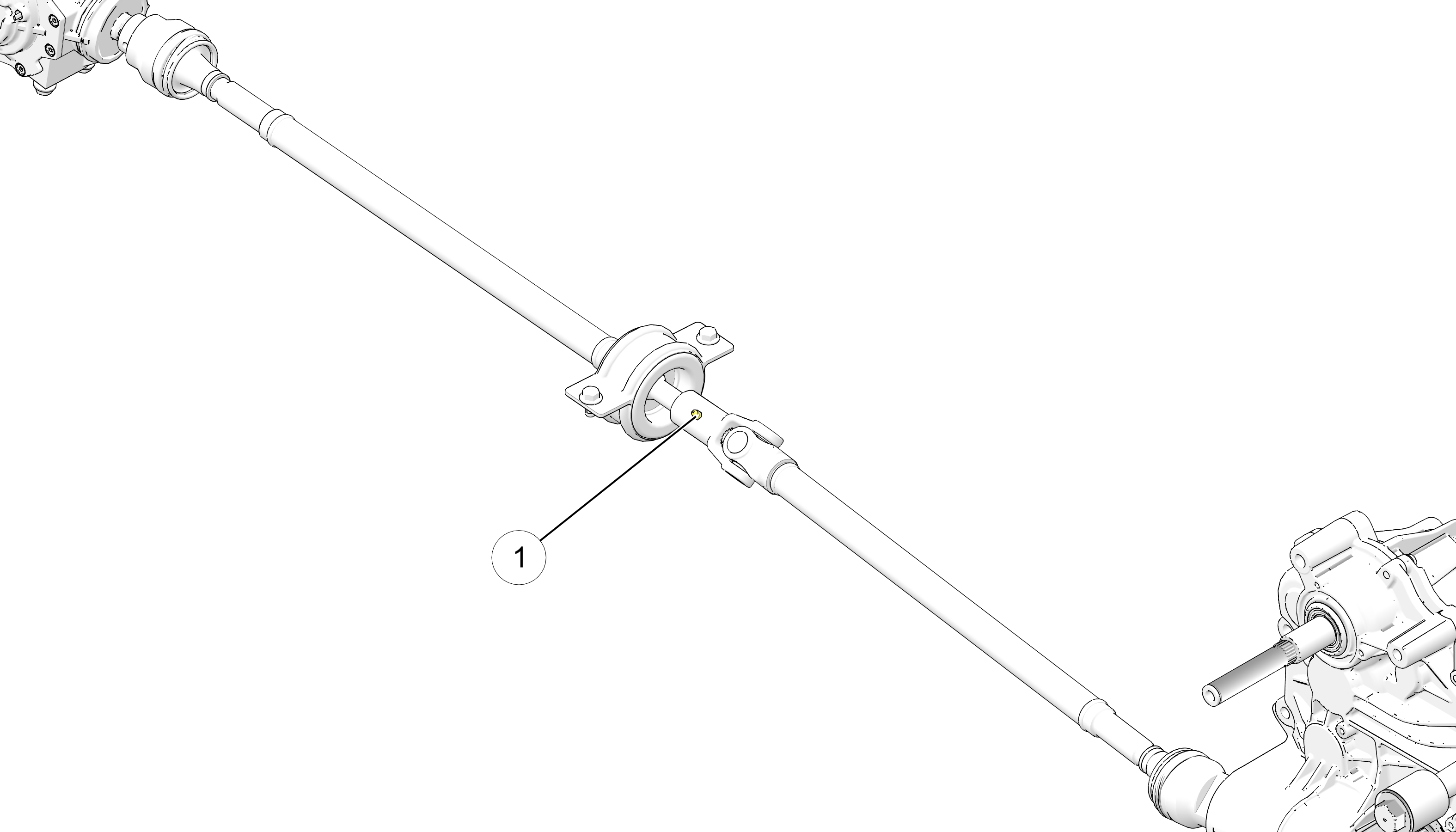
|
|
| CREW | |
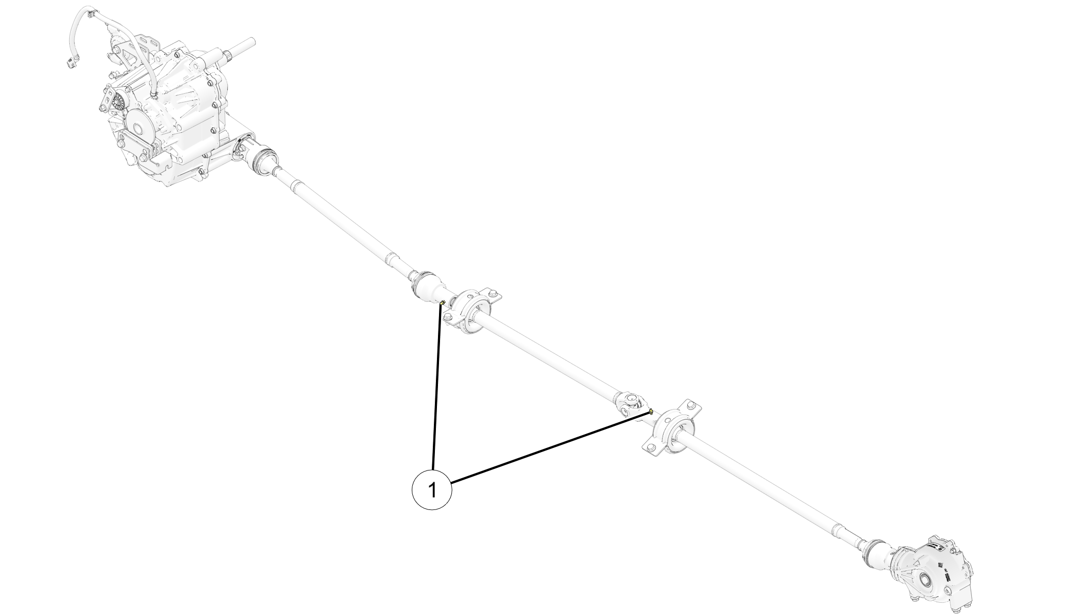
|
|
| Rear Stabilizer Bar Bushings, Right and Left Side | |
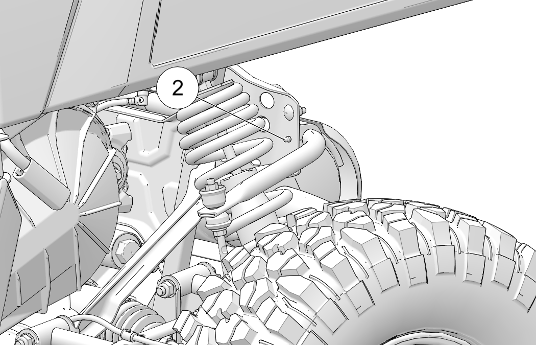
|
The engine coolant level is controlled or maintained by the recovery system. The recovery system components are the overflow bottle, radiator filler neck, radiator pressure cap and connecting hose.
As coolant operating temperature increases, the expanding (heated) excess coolant is forced out of the radiator, past the pressure cap, and into the overflow bottle. As engine coolant temperature decreases, the contracting (cooled) coolant is drawn back up from the tank, past the pressure cap, and into the radiator.
Some coolant level drop on new vehicles is normal as the system is purging itself of trapped air. Observe coolant levels and maintain as recommended by adding coolant to the overflow bottle.
POLARIS recommends the use of POLARIS Antifreeze 50/50 Premix. This antifreeze is already premixed and ready to use. Do not dilute with water.
To ensure that the coolant maintains its ability to protect the engine, we recommend that the system be completely drained every five (5) years and fresh Antifreeze 50/50 Premix added.
Any time the cooling system has been drained for maintenance or repair, replace the coolant with fresh Antifreeze 50/50 Premix. If the recovery bottle has run dry, the level in the radiator should be inspected. Add coolant as needed.
Always check and clean the screen and radiator fins at the intervals outlined in the Periodic Maintenance Chart. Do not obstruct or deflect air flow through the radiator by installing unauthorized accessories in front of the radiator or behind the cooling fan. Interference with the radiator air flow can lead to overheating and consequent engine damage.
Always check and clean the screen and radiator fins at the intervals outlined in the Periodic Maintenance Chart. Do not obstruct or deflect air flow through the radiator by installing unauthorized accessories in front of the radiator or behind the cooling fan. Interference with the radiator air flow can lead to overheating and consequentially, engine damage.

Lift the hood.
Slowly remove the radiator cap 1.
View the coolant level through the opening.
Use a funnel and slowly add coolant as needed.
Reinstall the pressure cap. Use of a non-standard pressure cap will not allow the recovery system to function properly. Your POLARIS dealer can provide the correct replacement part.
Always check and change the coolant at the intervals outlined in the Periodic Maintenance Chart. Maintain the coolant level between the minimum and maximum marks on the bottle (when the fluid is cool).
Position the vehicle on a level surface.
Lift the hood. View the coolant level in the overflow bottle 1.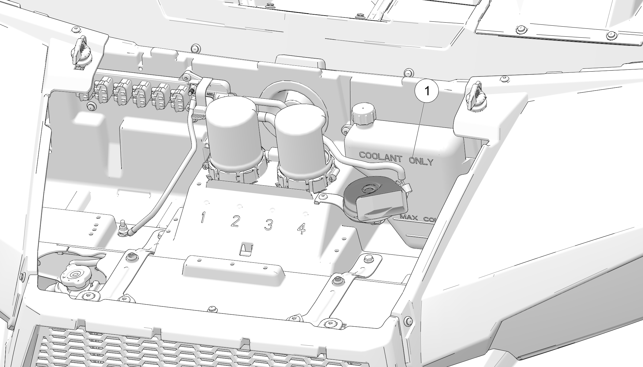
If the coolant level is below the safe operating range, lift the hood and locate the overflow bottle lid. Remove the cap and use a funnel to add coolant through the filler opening. Reinstall the cap.
Lift the bench seat and the box to gain access fuel lines.
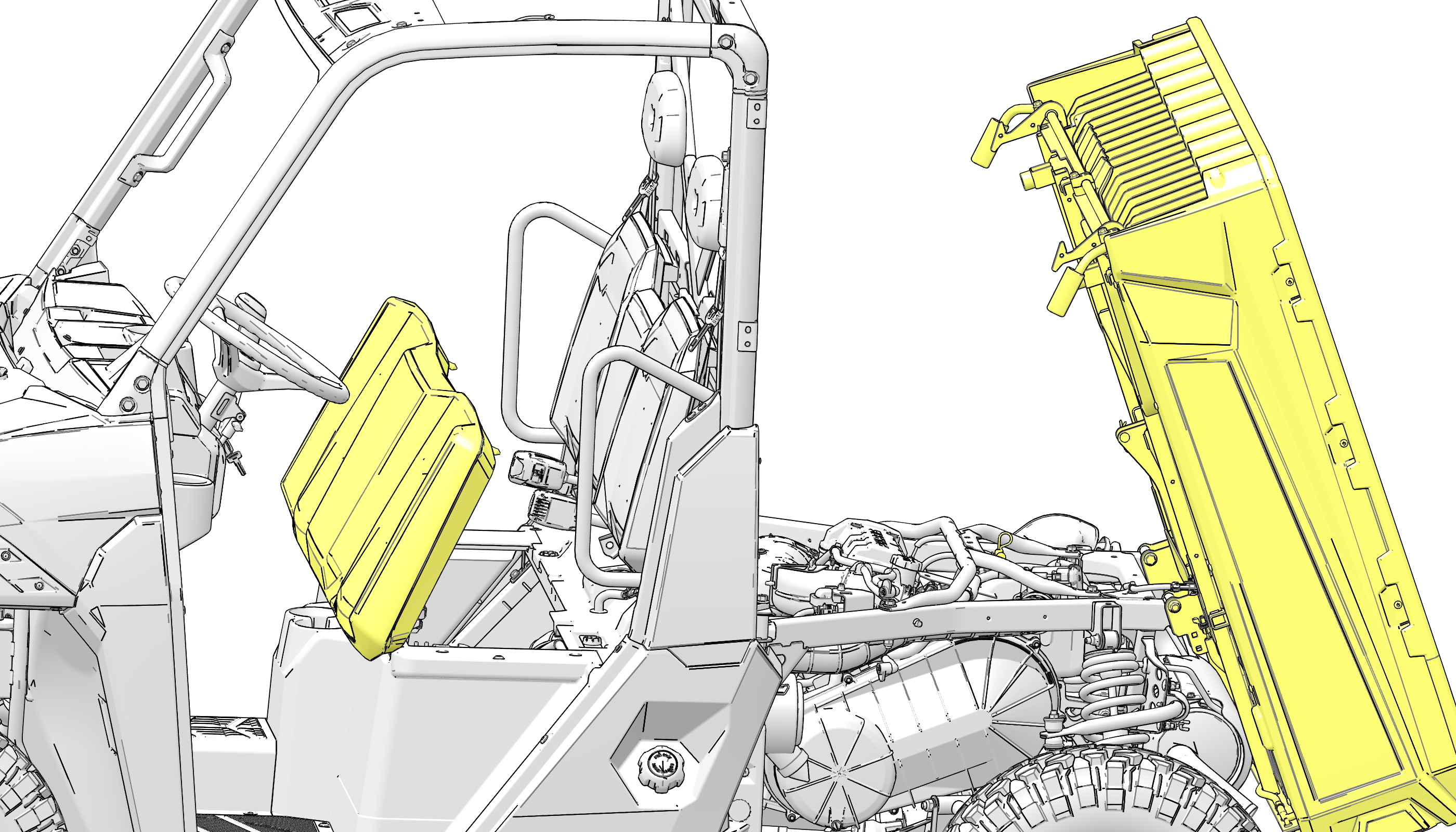
Inspect all fuel lines for leaks, cracks, and loose connections.
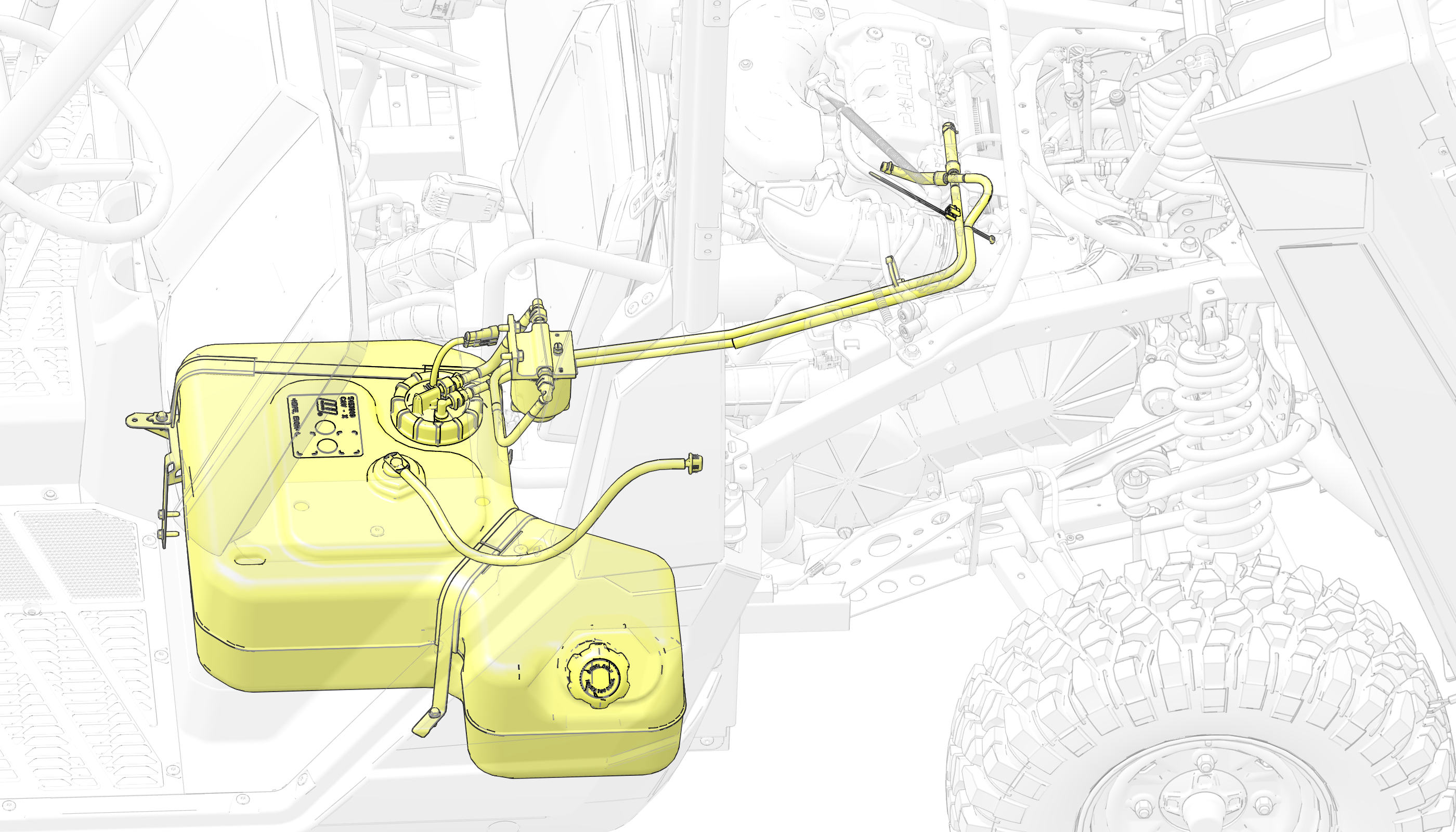
Failure to comply with the instructions in this warning can result in severe injury or death. Do not modify any component of the PVT system. Doing so may reduce its strength so that a failure may occur at a high speed. The PVT system has been precision balanced. Any modification will cause the system to be out of balance, creating vibration and additional loads on components.
The PVT system rotates at high speeds, creating large amounts of force on clutch components. As the owner, you have the following responsibilities for your own safety and the safety of others:
Always follow all recommended maintenance procedures. Always look for and remove debris inside and around the clutch and vent system when replacing the belt.
See your dealer or other qualified service person as outlined in the owner's manual.
This PVT system is intended for use on POLARIS products only. Do not install it in any other product.
Always make sure the PVT housing is securely in place during operation.
If a belt fails, always clean any debris from the clutch air duct and from the clutch and engine compartments when replacing the belt.
Inspect the entire clutch outlet duct (including the outlet duct screen) when replacing a drive belt. Remove any debris found in the outlet duct or outlet duct screen.
To remove the belt, do the following:
Remove the nine fasteners 1 that retain the outer clutch cover.

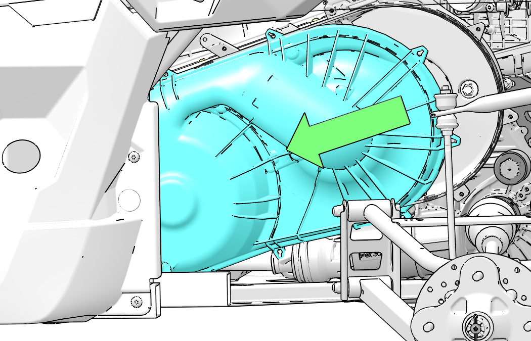
Removal of left rear wheel or left rear shock is NOT necessary for belt replacement.
Pull the clutch cover forward and slide towards the front of the vehicle as shown above.
Rotate the clutch cover back and lift up and over the control arm mounting 2.

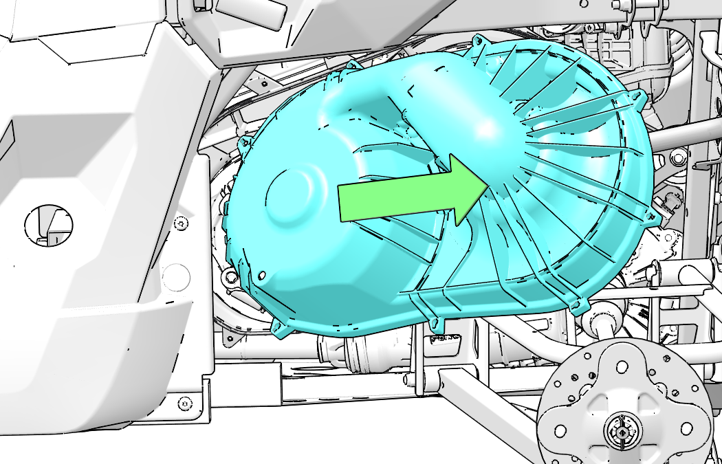
Pull clutch cover out towards the rear of the vehicle as shown above.
Mark the drive belt direction of rotation so that it can be installed in the same direction.
Insert clutch spreader tool 3 into threaded hole on driven clutch as shown and turn clockwise to spread clutch.
Clutch spreader tool part number 2875911.
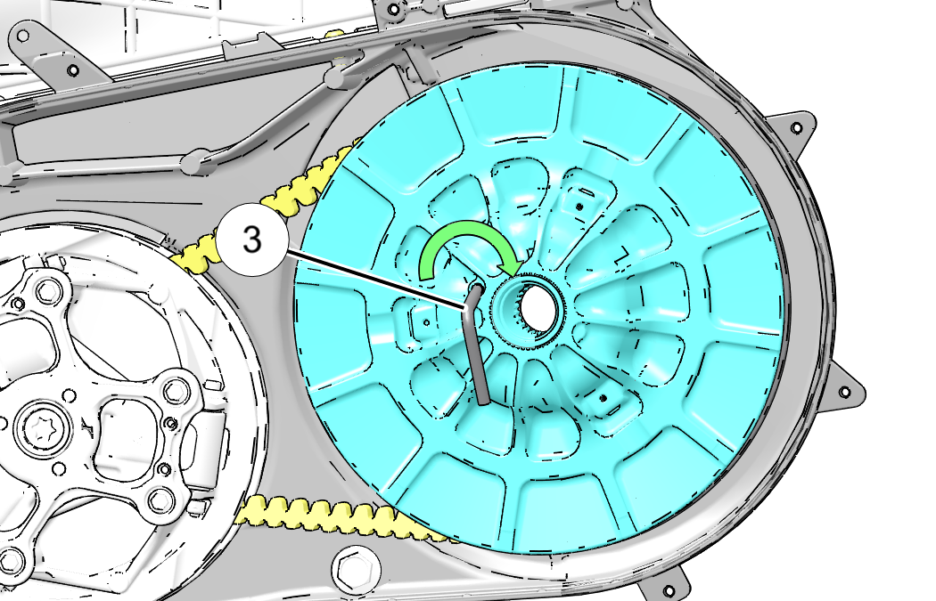
Walk the belt out of the driven clutch and drive clutch. Remove the belt from the vehicle.
To inspect the drive belt, do the following:
Inspect belt for hour-glassing (extreme circular wear in at least one spot and on both sides of the belt). Hour glassing occurs when the drive train does not move and the drive clutch engages the belt.
Inspect belt for loose cords, missing cogs, cracks, abrasions, thin spots, or excessive wear. Compare belt measurements with a new drive belt. Replace if necessary.
Belts with thin spots, burn marks, etc., should be replaced to eliminate noise, vibration, or erratic PVT operation.
Be sure to install belt in the same direction as it was removed.
With the clutch spreader tool 1 installed, loop the belt over the drive clutch and over the driven clutch.
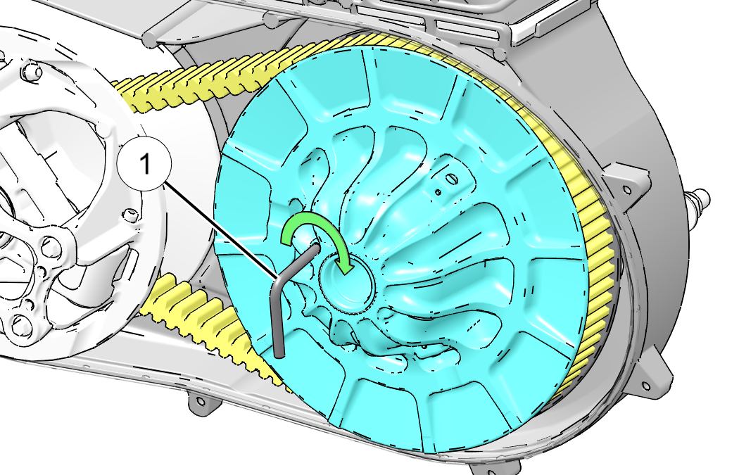
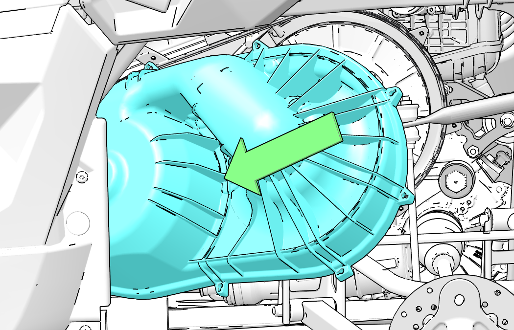
Rotate the driven clutch and walk the belt into the clutch.
Remove the clutch spreader tool from driven clutch.
Rotate / spin the driven clutch and belt approximately 5-7 times to properly seat the belt in the driven clutch.
Install the clutch cover into wheel well as shown above.
Rotate clutch cover over A-Arm 2 as shown below. Use care not to damage intake boots or electrical harness.
Pull clutch cover backwards and align with bolt holes on inner clutch cover as shown below.

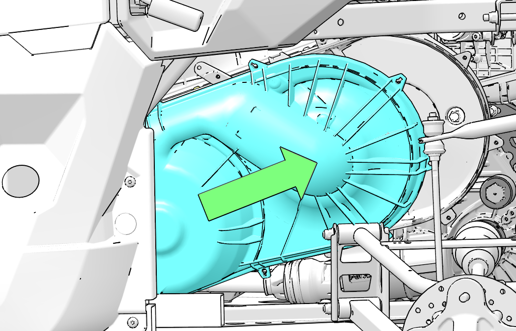
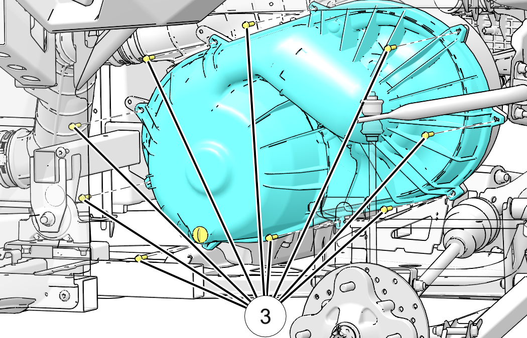
PVT Outer Cover Fasteners: 35 in-lb (4 N·m)
There may be some instances when water is ingested into the PVT system. Use the following instructions to dry it out before operating:
Position the vehicle on a level surface.
Remove the red drain plug on the outer clutch cover. Allow the water to drain completely. Reinstall the drain plug.
Place the transmission in PARK.
Start the engine.
Apply varying throttle for 10-15 seconds to expel the moisture and air-dry the belt and clutches. Do not hold the throttle wide open for more than five (5) seconds.
Allow the engine RPM to settle to idle speed. Apply the brakes. Shift the transmission to the lowest available range.
Test for belt slippage. If the belt slips, repeat the process.
Your vehicle requires service as soon as possible. Your POLARIS dealer can assist.
Ensure that shift cable/linkage is clean, free of debris, operation is smooth and cable boot is not damaged. If operation is not smooth or if the cable boot is damaged or torn, contact an authorized dealer for service.
If it's impossible to take your vehicle in for service before starting it, follow the steps outlined below:
Move the vehicle to dry land, or at the very least to water below the floorboard.
Inspect the air box for water.
If the air box is wet but has no visible water, dry the air box.
Thoroughly dry the air pre-cleaner located under the hood.
Take the vehicle in for service as soon as possible, whether you succeed in starting it or not. Your POLARIS dealer can provide the required service.
If water has been ingested into the PVT, follow the procedure for drying in the POLARIS Variable Transmission (PVT) Drying section.
Inspect the air filter at the intervals outlined in the Periodic Maintenance Chart. In extremely dusty conditions, air filter replacement will be required more often.

Locate the air filter on the left side of the unit.
Release the two airbox 2 cover latches.
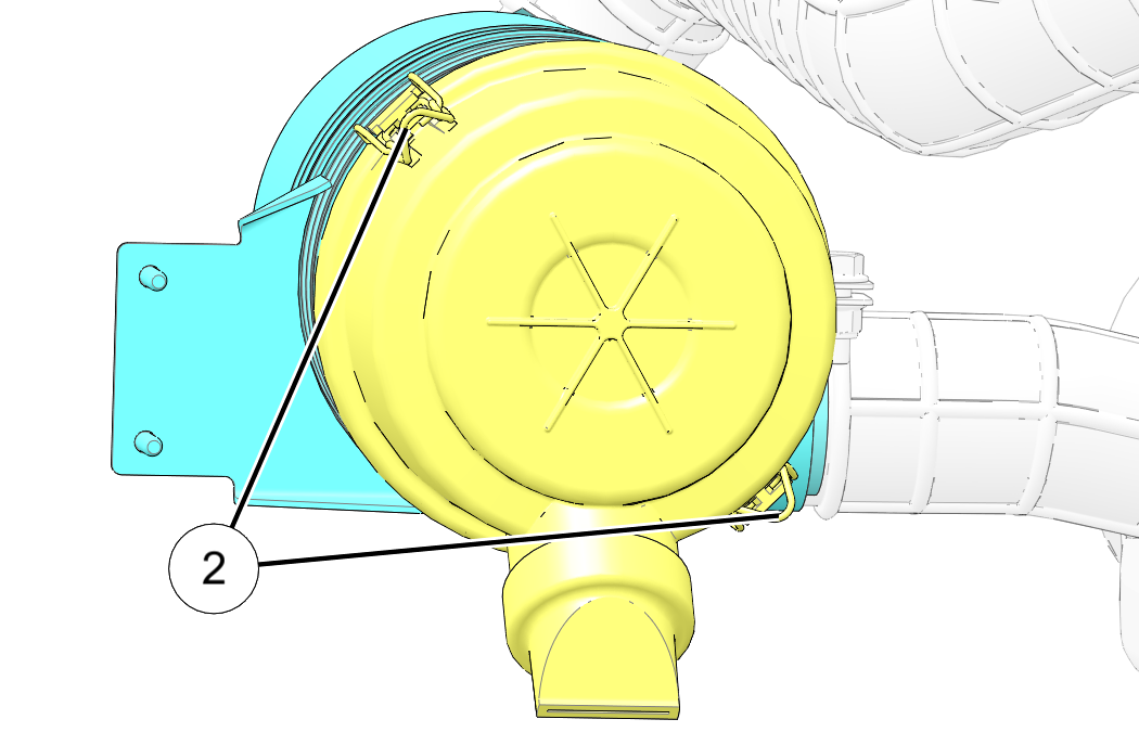
Remove the cover 3 to access the air filter element 4.
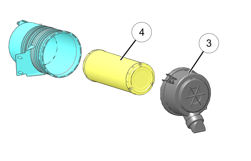
Inspect the airbox for oil or water deposits. Wipe away any deposits with a clean shop towel.
If the filter has been soaked with fuel or oil it must be replaced.
DO NOT attempt to clean the air filter.
Place the air filter into the airbox. Reposition the airbox cover and install the two retaining latches.
Make sure the hinge pins are properly seated when reassembling the airbox
Inspect the intake ducts between the filter and engine for loose connections, cracking, etc. Ensure clamps are tight.
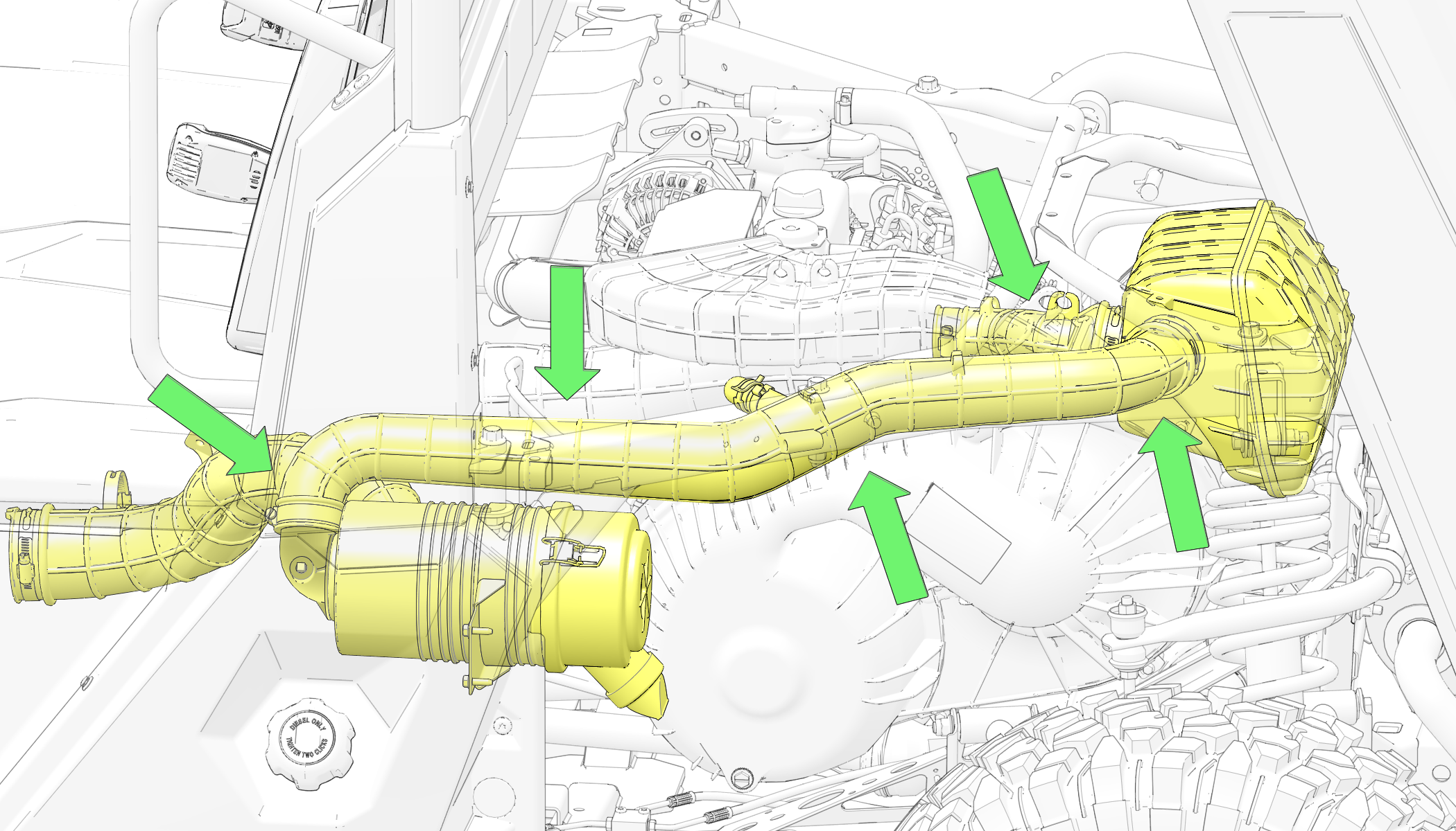
Never operate the vehicle without the spark arrester.
Remove any combustible materials from the area.
Failure to heed the following warnings while servicing the spark arrestor could result in serious injury or death.
Never run the engine in an enclosed area. Exhaust contains poisonous carbon monoxide gas that can cause loss of consciousness or death in a very short time.
Do NOT perform service on the spark arrester while the system is HOT. Exhaust system temperatures can reach extreme temperatures. Allow components to cool sufficiently before proceeding.
Do not stand behind or in front of the vehicle while purging the exhaust system.
Never go under the vehicle while it is inclined.
Wear eye protection and gloves while servicing.
Use the following procedure to periodically purge accumulated carbon from the exhaust pipe.
Turn off engine and allow exhaust to cool sufficiently.
Remove the spark arrester from the tailpipe of the muffler.
Remove any debris from spark arrester and the tailpipe.
Inspect spark arrester for holes in mesh screen. Replace as needed.
Replace spark arrester and torque bolt to specification.
Belt Adjustment
Check the alternator belt at the correct service interval as outlined in the Periodic Maintenance Chart.
Stop the machine on a flat level surface. Put the gear selector in Park, stop the engine and exit the vehicle. See the Stopping the Engine section.
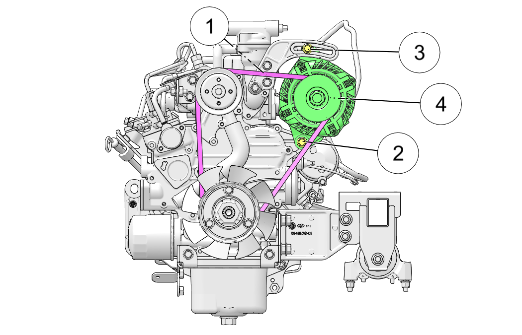
Raise the cargo box.
The belt tension is correct with 0.3 in (7.6 mm) of belt deflection at the mid span at the top of the belt 1, when 20 lb (89 n) of force is applied to the belt.
If the belt tension is not correct, loosen the mounting bolt 2 and adjustment bolt 3.
Move the top of the alternator 4 to tighten the belt.
Tighten the adjustment bolt to 20 ft-lbs (27 N·m).
Tighten the mounting bolt to 20 ft-lbs (27 N·m).
Lower the cargo box.
The fuel filter/water separator is located under the seat on the left side of the vehicle, between the engine and fuel tank.
Inspect the separator daily for leaks. Drain water and replace the separator at the intervals outlined in the Periodic Maintenance Chart. Service the separator more frequently if the vehicle is operated with inferior fuel.
Be sure the engine is at room temperature.
Disconnect the battery.
Remove the seat.
Locate the fuel filter / water separator.
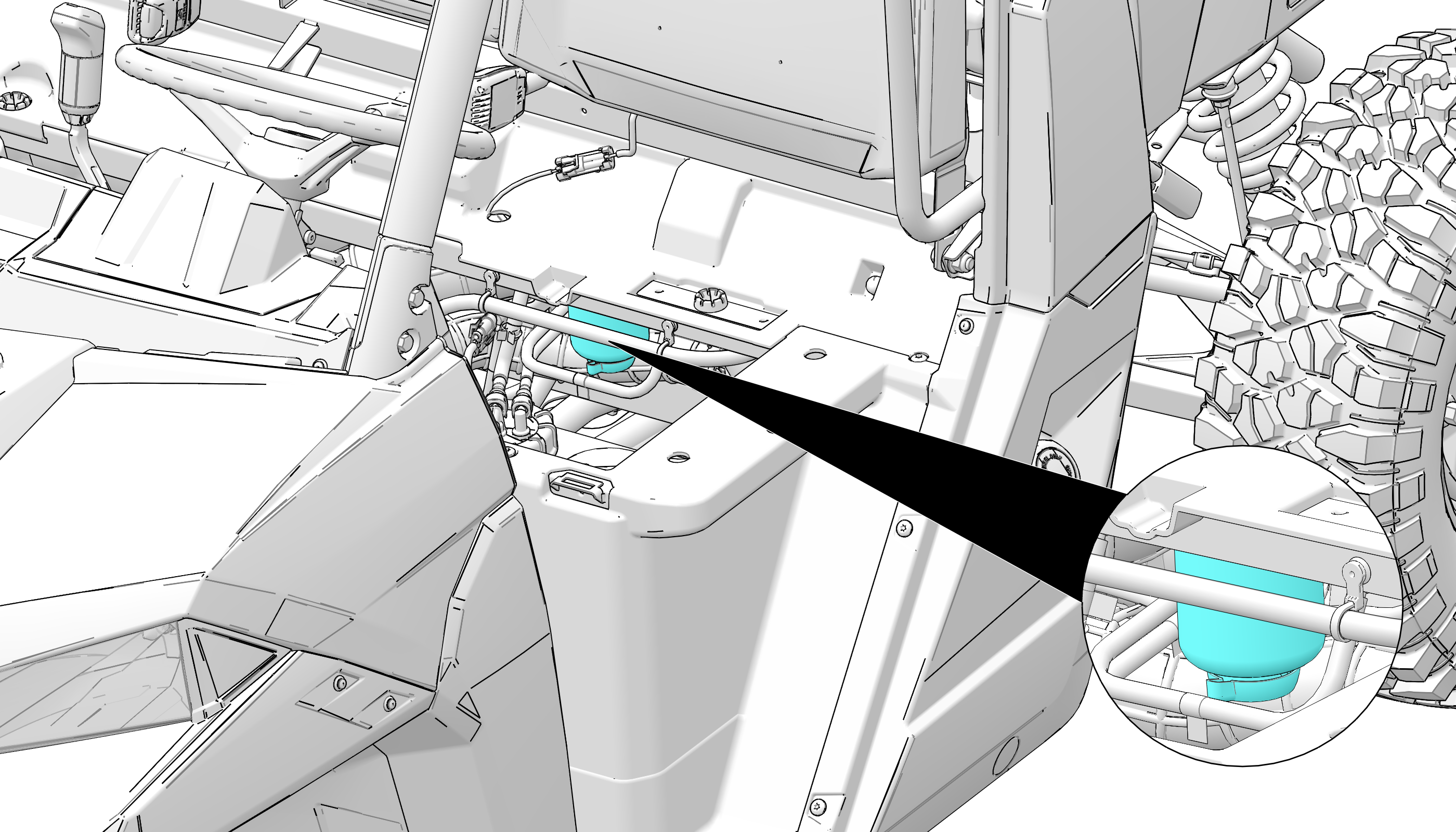
Place an appropriate container under the fuel filter area to catch any excess fuel from the drain valve.
Unscrew the drain value 1/2 to 1 full turn until fuel starts to drain from the bottom – do NOT unscrew the valve completely.
The drain valve has standard threads.
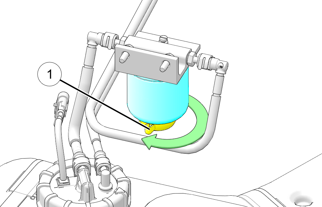
Wait for fuel and water to stop draining and then firmly retighten valve.
Clean up any excess fuel.
Reconnect the battery.
Prime the fuel system by turning the ignition switch to the “ON” position for 10–15 seconds.
Start the engine and verify that no fuel leaks are present.
Reinstall the seat.
Be sure engine is at room temperature.
Remove seat.
Drain fuel filter / water separator. See Fuel Filter / Water Separator.
Unscrew fuel filter / water separator 1 from the filter mount using a commercially available filter wrench if not able to remove by hand.
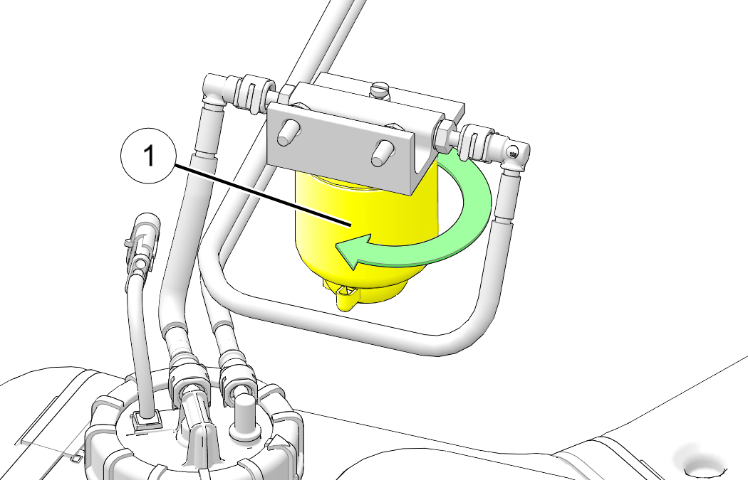
The filter has standard threads.
Properly drain and dispose of the old fuel filter / water separator.
Lightly lubricate the rubber gasket of the New fuel filter / water separator with fresh engine oil.
Fuel Filter / Water Separator:
Thread onto the mount until the gasket lightly touches the filter housing. Tighten an additional 1/2–3/4 turn.
Ensure the drain valve on the bottom of the filter is snug and did not loosen up during filter installation.
Clean up any excess fuel.
Reconnect battery.
Prime fuel system by turning ignition to “ON” position for 10–15 seconds.
Start engine and verify that no fuel leaks are present.
Reinstall seat.
Failure to check or maintain proper operation of the throttle system can result in an accident and lead to serious injury or death if the throttle pedal sticks during operation.
Always check the pedal for free movement and return before starting the engine and occasionally during operation. Never start or operate this vehicle if it has a sticking or improperly operating throttle pedal. Immediately contact your dealer for service if throttle problems arise.
If the throttle pedal has excessive play due to cable stretch or maladjustment, it will cause a delay in throttle response, especially at low engine speed. The throttle may also not open fully. If the throttle pedal has no freeplay, the throttle may be hard to control, and the idle speed may be erratic.
Check the throttle pedal freeplay at the intervals outlined in the Periodic Maintenance Chart. Adjust the freeplay if necessary.
Apply the brakes. Engage the park brake. Shift the transmission to neutral.
Remove grass, leaves, foreign matter, and other flammable material or debris from the throttle linkage and components.
Start the engine. Allow it to warm up thoroughly.
Measure the distance the throttle pedal moves before the engine begins to pick up speed. Freeplay should be 1/16–1/8 in (1.6–3.2 mm).
Idle RPM is preset by the manufacturer. If the engine idle speed is not satisfactory, please see your POLARIS dealer for adjustment.
Ensure that the throttle cable is properly routed and retained to the unit.

On the pedal side, tighten jam nuts 1.
Throttle Cable Jam Nut (pedal side): 43 in-lbs (5 N·m)
On the engine side, tighten jam nuts 2.
Throttle Cable Jam Nut (engine side): 10 ft-lbs (13 N·m)
Slide back the protective cover to expose the jam nut 3 and adjuster screw4.
Loosen the jam nut and turn the adjuster screw until the throttle lever on the engine moves.
Loosen the adjuster back so there is no tension in the cable.
Once properly adjusted, tighten the jam nut against the adjuster and re-install the protective sleeve.
Start the engine and allow if to warm up thoroughly. Measure the distance the throttle pedal moves before the engine begins to pick up speed. Freeplay should be 1/16–1/8 in (1.6–3.2 mm).
It is ideal to adjust the throttle pedal with the help of an assistant.
Loosen the adjustment screw 1 and jam nut 2.

With the vehicle off and in park, have the assistant fully depress and hold down the throttle pedal.
The person on the engine side should manually press the lever on the engine to ensure that full travel is being achieved.
Release the pedal and engine lever and adjust the pedal adjustment screw out 1/2 turn at a time and continue this process until full travel of the engine lever is NOT obtained.
Slowly adjust the pedal adjuster in a 1/4 turn at a tie until the full engine throttle IS obtained. Once proper adjustment is obtained, tighten jam nut in place to hold the adjustment position.
Throttle Pedal Adjuster Jam Nut: 14 ft-lbs (19 N·m)
With the unit in park, start the unit. Ensure the engine idle is still within range of 1200 +/- 100 RPM. Fully depress the throttle pedal and ensure that the engine RPM gets to 3850 +/- 50 RPM.
DO NOT HOLD hold the unit wide open for more than 10 seconds.
The front and rear brakes are hydraulic disc type brakes. Press down on the brake pedal to engage the brakes.
Inspect the brake system routinely. Inspect the level of the brake fluid before each operation.
Change the brake fluid every two years and any time the fluid becomes contaminated, the fluid level is below the minimum, or if the type and brand of the fluid in the reservoir are unknown.
Position the vehicle on a level surface and turn off the engine.
View the brake fluid level at the reservoir in the driver’s side wheel well. The level should be between the upper (MAX) and lower (MIN) level lines.
If the fluid level is lower than the upper level line, open the hood and add brake fluid to the upper (MAX) line.
Apply the brake forcefully for a few seconds and check for fluid leakage around the fittings.
Do not apply WD-40® or any petroleum product to brake discs. These types of products are flammable and may also reduce the friction between the brake pad and caliper.
Check the brake system for fluid leaks.
Check the brake pedal for excessive travel or a spongy feel.
Check the friction pads for wear, damage and looseness.
Check brake discs for signs of cracks, excessive corrosion, warping or other damage. Clean any grease using an approved brake cleaner or alcohol.
Inspect the brake disc spline and pad wear surface 1 for excessive wear. Change pads when worn to 0.040 in (1 mm).
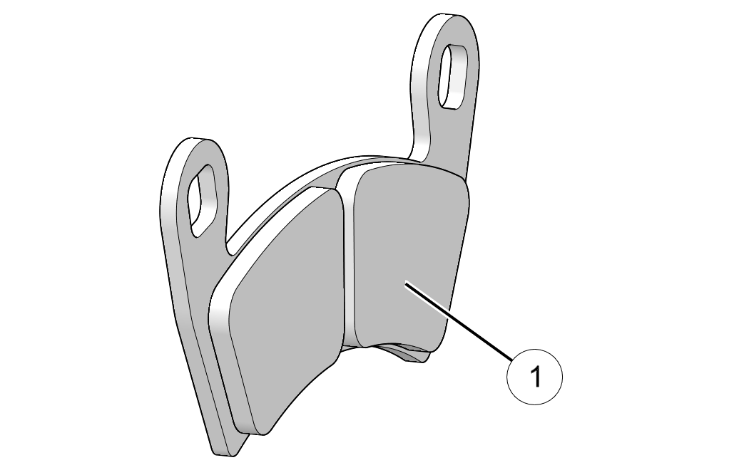
Apply the service brakes, and pull the park brake lever.
While engaging the parking brake lever, verify the following:
The ratchet teeth should be heard and felt as the locking pawl clicks into place.
After a few clicks, the park brake indicator lamp on the instrument cluster should illuminate.
The rear wheels of the vehicle should not rotate when turning by hand.
Ensure that plenty of resistance is felt in the lever's throw before fully extended to the hard stop.
When the park brake is fully engaged, the vehicle should not roll while parked.
If park brake fails inspection, contact your dealer for adjustment/repairs.
Check the steering for specified freeplay, smooth operation, and inspect the steering boots at the intervals outlined in the Periodic Maintenance Chart section.
Position the vehicle on level ground.
Lightly turn the steering wheel left and right.
There should be 0.8-1.0 in (20-25 mm) of freeplay.
If there is excessive free play or strange noises, or the steering feels rough or “catchy,” have the steering system inspected by an authorized dealer.
Inspect boots 1 for tears. If a tear is discovered, have the boot replaced by an authorized dealer.
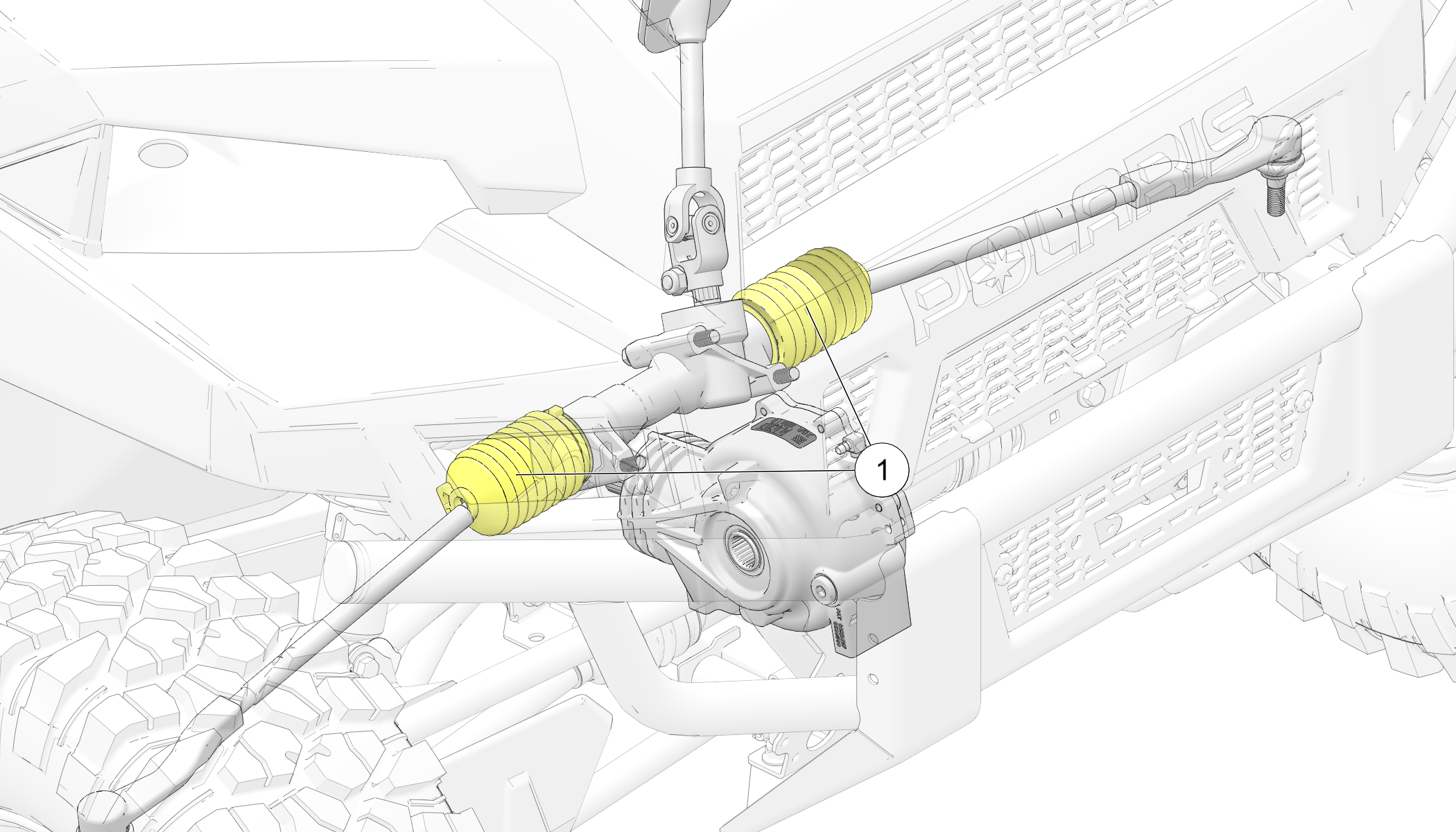
Position the vehicle on a level surface.
Apply the brakes. Put the vehicle in PARK, and set the park brake (if equipped). Turn the key off.
Elevate front end of machine so front wheels are off the ground by placing a suitable stands under the frame.
Check for any looseness in front wheel/hub assembly by grasping
the tire firmly at top and bottom first, and then at front and rear.
Try to move the wheel and hub by pushing inward and pulling outward.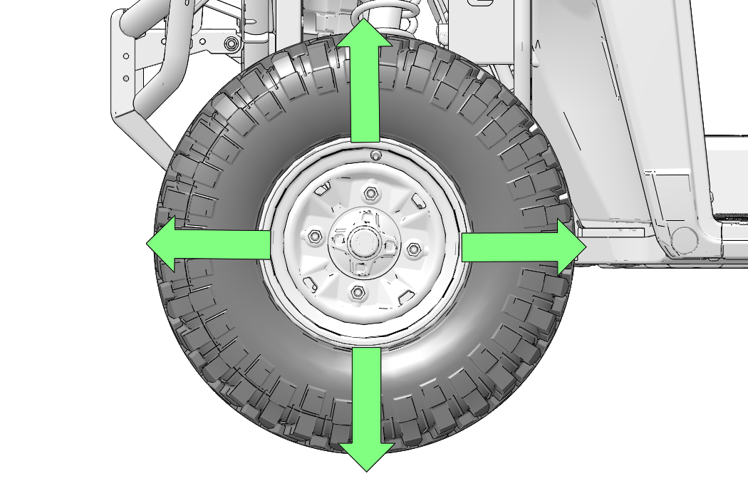
If abnormal movement is detected, take the vehicle to your dealer for service.
Repeat the procedure for the rear wheels.
Inspect inboard and outboard boots on both sides of the vehicle, front 1 and rear 2, for tears. If a tear is discovered, have the boot replaced by an authorized dealer.
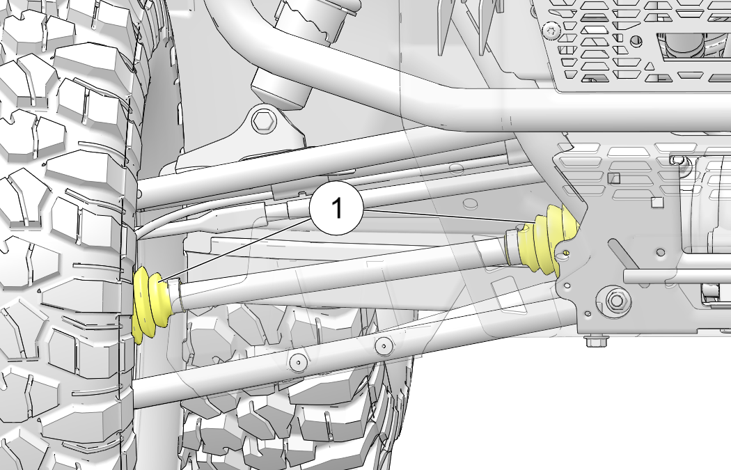
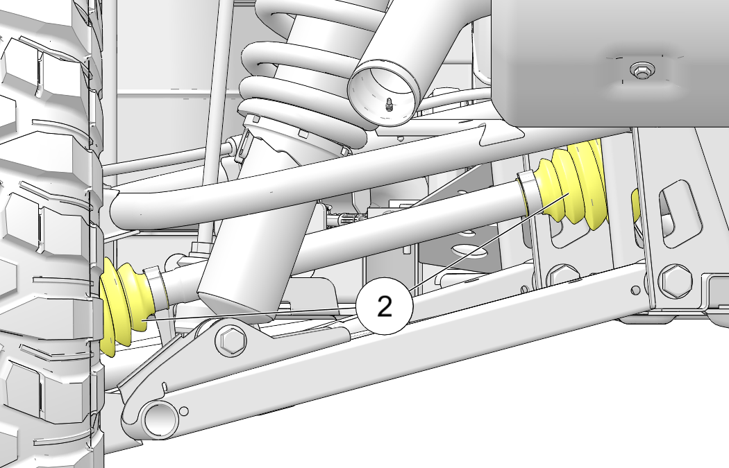
Adjust the front and rear shock absorber springs by rotating the adjustment cam 1 either clockwise or counterclockwise to increase or decrease spring tension.
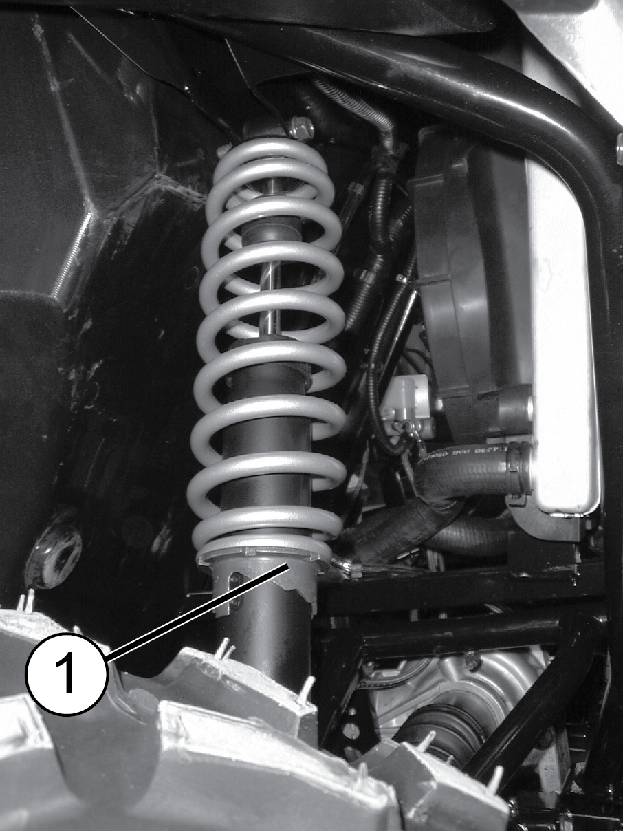
Operating your vehicle with worn tires will increase the possibility of skidding, loss of control and an accident, which could result in serious injury or death. Always replace tires when the tread depth measures 1/8 in (3 mm) or less.
Improper tire inflation or the use of non-standard size or type of tires may adversely affect vehicle handling, which could result in vehicle damage or personal injury. Always maintain proper tire pressure. Always use POLARIS approved size and type of tires for this vehicle when replacing tires.
Always replace tires when tread depth is worn to 1/8 in (3 mm) or less.
Tire rotation is recommended for every 500 mi (800 km) interval. Perform tire rotation on the vehicle by following the rearward cross strategy as shown.
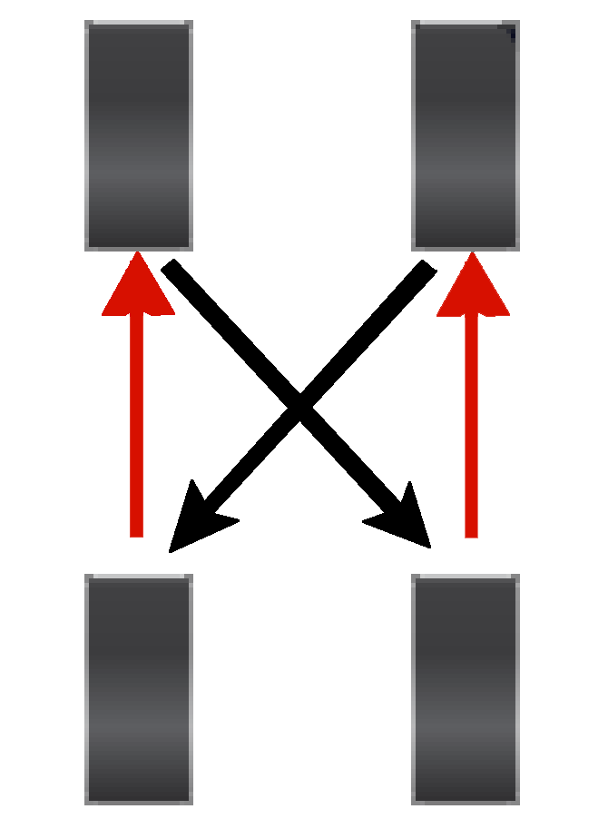
Inspect the following items occasionally for tightness, and if they've been loosened for maintenance service. Do not lubricate the stud or the lug nut.
| Lug Nut (Aluminum Wheels) |
|
Front and Rear | 120 ft-lbs (163 N·m) |
| Tapered Lug Nut (Steel Wheels) |
|
Front and Rear | 60 ft-lbs (81 N·m) |
| Spindle Nut | Front | 110 ft-lbs (149 N·m) | |
| Hub Retaining Nut | Rear | 180 ft-lbs (244 N·m) | |
Position the vehicle on a level surface.
Place the transmission in PARK. Stop the engine.
Loosen the wheel nuts slightly.
Elevate the side of the vehicle by placing a suitable stand under the frame.
Remove the wheel nuts and washers. Remove the wheel.
Place the transmission in PARK.
Place the wheel on the hub with the valve stem toward the outside and rotation arrows on the tire pointing toward forward rotation.
Attach the wheel nuts and washers and finger-tighten.
Carefully lower the vehicle to the ground.
Torque the wheel nuts to specification.
If your model is equipped with power steering, frequently clean the areas around and on the power steering unit to allow proper cooling. Clean these areas 3 thoroughly.
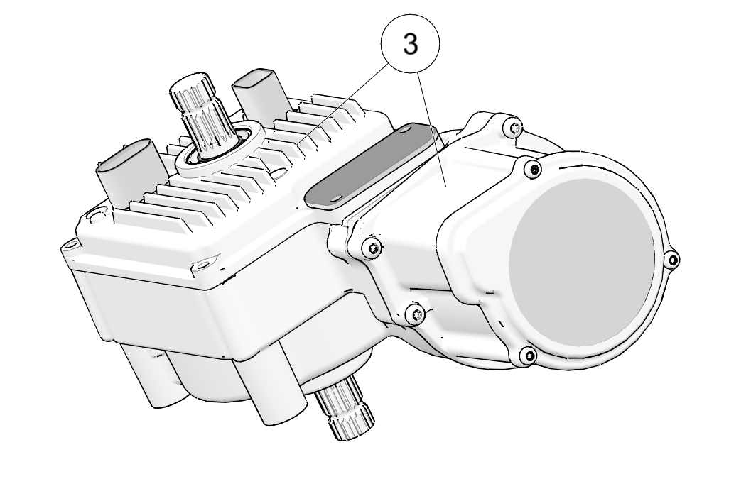
Poor lighting can result in reduced visibility when driving. Headlight and taillight lenses become dirty during normal operation. Clean lights frequently and replace burned out lamps promptly. Do not operate this vehicle at night or in low light conditions until the headlight is replaced. Always make sure lights are adjusted properly for best visibility.
When servicing a halogen lamp, don't touch the lamp with bare fingers. Oil from your skin leaves a residue, causing a hot spot that will shorten the life of the lamp.
Remove the hood from the front cab.
Locate the bulb on the back side of the headlight housing.
Disconnect the harness from the bulb. Be sure to pull on the connector, not on the wiring.
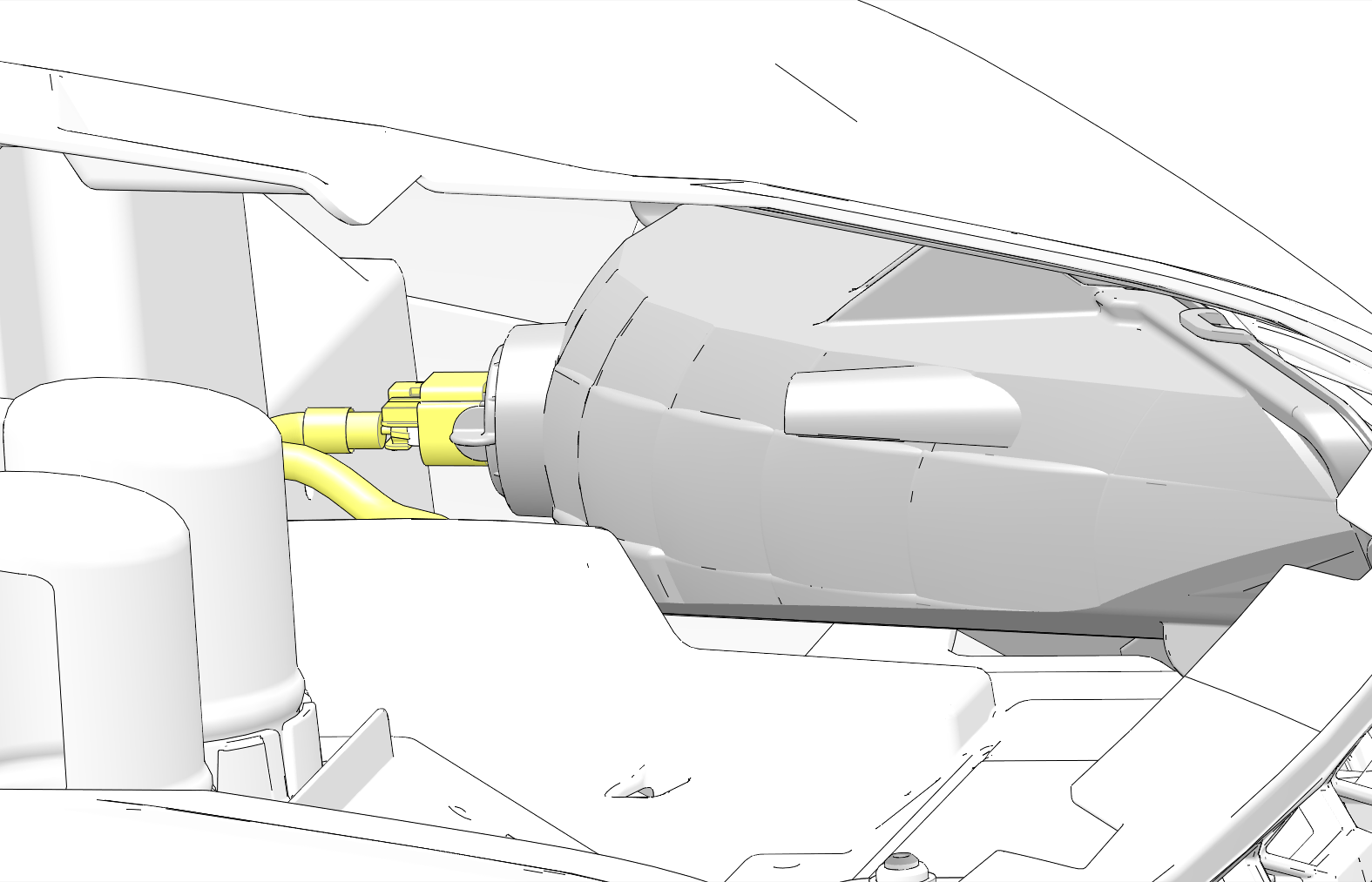
Turn the bulb counterclockwise and remove it from the headlight housing.
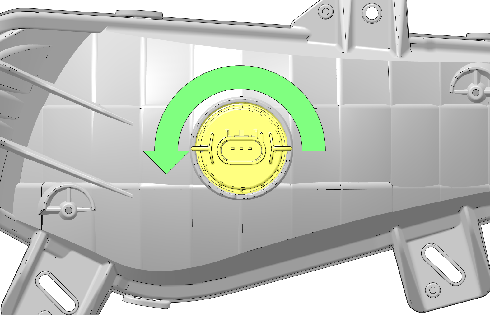
Install the new bulb into the housing and rotate it clockwise 90° to lock it in place.
Make sure the tab on the bulb locates properly in the housing.
Install the harness onto the new headlight bulb and install the hood.
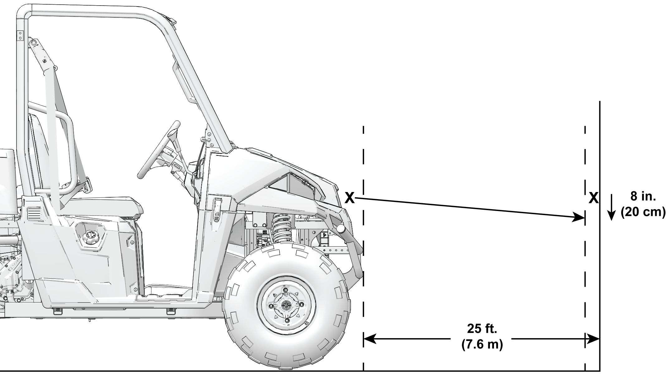
To adjust the headlight beam, do the following:
Place the vehicle on a level surface with the headlight approximately 25 ft (7.6 m) from a wall.
Measure the distance from the floor to the center of the headlight and make a mark on the wall at the same height.
Apply the brakes. Start the engine. Turn on the headlights.
Observe the headlight aim. The most intense part of the headlight beam should be aimed 8 in (20 cm) below the mark placed on the wall. Include the weight of a rider on the seat while performing this step.
If a headlight needs adjustment, locate the adjustment screw at the back of the headlight.
Loosen the screw, adjust the headlight, and tighten the screw.
Repeat steps 4-6 until the lamp is properly adjusted.
When the brake pedal is depressed, the brake light comes on. Check the brake light before each ride.
To check the brake lights, do the following:
Turn the key to the ON position.
Depress the brake pedal. The brake light should come on after about 0.4 in (10 mm) of pedal travel. If the light doesn't come on, check the bulb.
If the engine stops or will not start, or if you experience other electrical failures, a fuse may need replacement. Locate and correct any short circuits that may have caused the blown fuse, then replace the fuse. The fuse box is located under the seat 1. Spare fuses are provided in the fuse box.
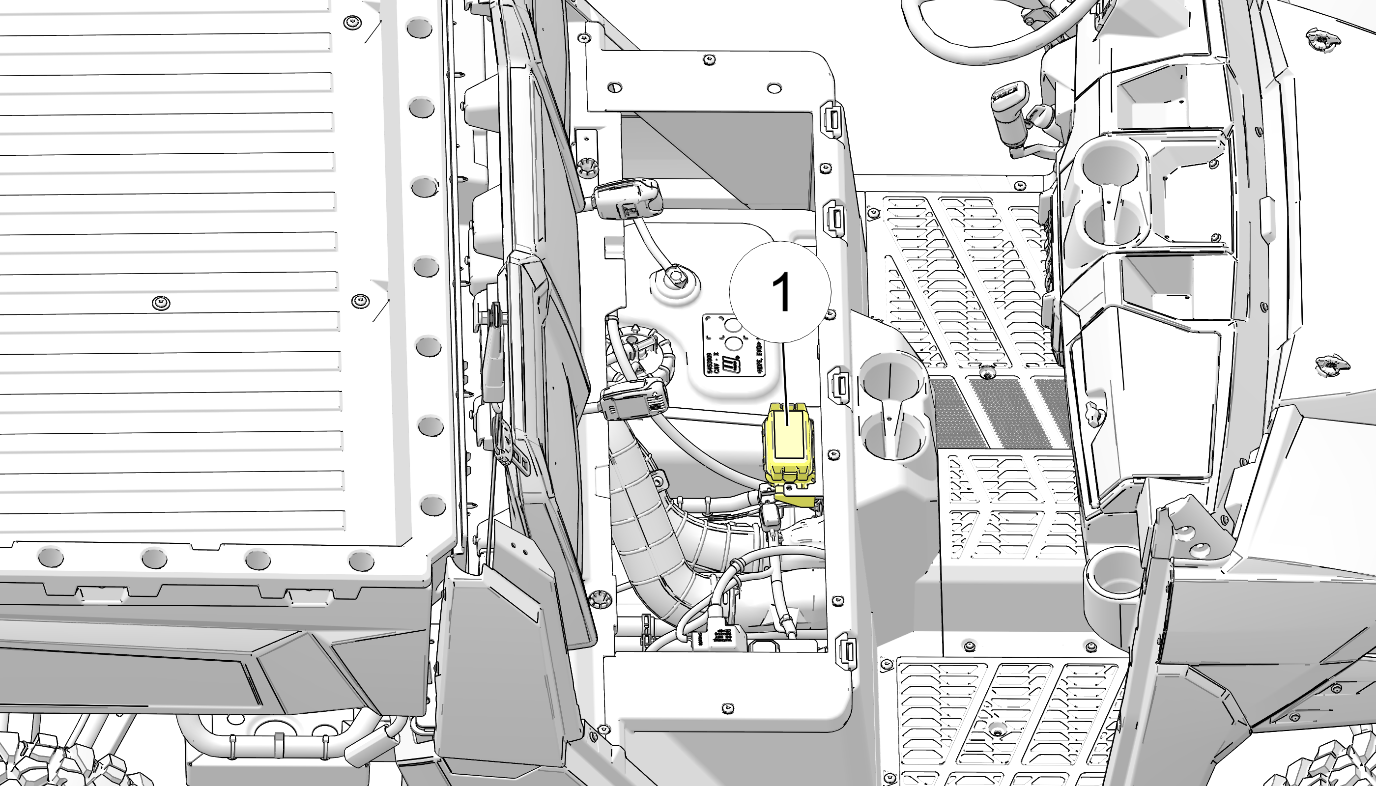
If you suspect that a fuse or relay may not be working properly, your dealer can assist.
| Fuse Size | Feature Supported |
|---|---|
| 70A | Glow Plug Relay |
| 40A | Glow Plugs |
| 30A | Starter Solenoid (4000 models) |
| 30A | EPS |
| 20A | Starter Solenoid (2000 models) |
| 20A | Chassis |
| 20A | Accessories |
| 15A | Lights |
| 15A | EFI (Engine Controller) |
| 10A | Charge Receptacle |
| 10A | Horn |
| 10A | Brakes |
| 10A | Fuel Pump |
| 10A | Alternator |
| 10A | Drive Mode |
Your vehicle has a sealed battery, which requires little maintenance. Always keep battery terminals and connections free of corrosion. If cleaning is necessary, remove the corrosion with a stiff wire brush. Wash with a solution of one tablespoon baking soda and one cup water. Rinse well with tap water and dry off with clean shop towels. Coat the terminals with dielectric grease or petroleum jelly.
Lift seat to access battery.
Disconnect the black (-) battery cable first. Disconnect the red (+) battery cable last.
Remove the battery hold-down strap.
Lift the battery out of the vehicle.
Using a new battery that has not been fully charged can damage the battery and result in a shorter life. It can also hinder vehicle performance. Follow the battery charging instructions before installing the battery.
Ensure that the battery is fully charged.
Place the fully charged battery in the battery holder. Make sure the positive terminal is toward the driver’s side of the vehicle.
Coat the terminals with dielectric grease or petroleum jelly.
Connect and tighten the red (+) cable first. Connect and tighten the black (-) cable last.
Install the hold-down strap.
Reinstall the seat.
Whenever the vehicle is not used for a period of three months or more, remove the battery from the vehicle, ensure that it's fully charged, and store it out of the sun in a cool, dry place. Check battery voltage each month during storage and recharge as needed to maintain a full charge.
Battery charge can be maintained by using a battery trickle charger or by charging about once a month to make up for normal self discharge. See the Polaris Products section for the part number.
The following battery charging instructions apply only to the installation of a sealed battery. Read all instructions before proceeding with the installation of this battery.
The sealed battery is already filled with electrolyte and has been sealed and fully charged at the factory. Never pry the sealing strip off or add any other fluid to this battery.
The single most important thing about maintaining a sealed battery is to keep it fully charged. Since the battery is sealed and the sealing strip cannot be removed, you must use a voltmeter or multimeter to measure DC voltage.
For a refresh charge, follow all instructions carefully.
Check the battery voltage with a voltmeter or multimeter. A fully charged battery will register 12.8 V or higher.
If the voltage is less than 12.8 volts, recharge the battery at 1.2 amps or less until battery voltage is 12.8 or greater.
When using an automatic charger, refer to the charger manufacturer's instructions for recharging. When using a constant current charger, use the guidelines below for recharging.
Always verify battery condition before and 1-2 hours after the end of charging.
|
State of Charge |
Voltage |
Action |
Charge Time* |
|---|---|---|---|
|
100% |
12.8-13.0 volts |
None, check at 3 mos. from date of manufacture |
None required |
|
75%-100% |
12.5-12.8 volts |
May need slight charge, if no charge given, check in 3 months |
3-6 hours |
|
50%-75% |
12.0-12.5 volts |
Needs charge |
5-11 hours |
|
25%-50% |
11.5-12.0 volts |
Needs charge |
At least 13 hours, verify state of charge |
|
0%-25% |
11.5 volts or less |
Needs charge with desulfating charger |
At least 20 hours |
*(Using constant current charger @ standard amps specified on top of battery)
Keeping your POLARIS vehicle clean will not only improve its appearance but it can also extend the life of various components.
The best and safest way to clean your POLARIS vehicle is with a garden hose and a pail of mild soap and water.
Use a professional-type washing cloth, cleaning the upper body first and the lower parts last.
Rinse with clean water frequently.
Dry surfaces with a chamois to prevent water spots.
Avoid the use of harsh cleaners, which can scratch the finish.
Do not use a power washer to clean the vehicle.
Do not use medium to heavy duty compounds on the finish.
Always use clean cloths and pads for cleaning and polishing. Old or reused cloths and pads may contain dirt particles that will scratch the finish.
Grease all zerk fittings immediately after washing. Allow the engine to run for a while to evaporate any water that may have entered the engine or exhaust system.
If a high pressure water system is used for cleaning (not recommended), exercise extreme caution. The water may damage components and could remove paint and labels. Avoid directing the water stream at the following items:
Wheel bearings
Radiator
Transmission seals
Brakes
Door seals (if equipped)
Cab and body panels
Labels and decals
Electrical components and wiring
Air intake components
Window seals (if equipped)
If an informational or graphic label becomes illegible or comes off, contact your POLARIS dealer, or other qualified person, to purchase a replacement. Replacement safety labels are provided by POLARIS at no charge.
POLARIS recommends the use of common household aerosol furniture polish for polishing the finish on your POLARIS vehicle. Follow the instructions on the container.
Avoid the use of automotive products, some of which can scratch the finish of your vehicle.
Always use clean cloths and pads for cleaning and polishing. Old or reused cloths and pads may contain dirt particles that will scratch the finish.
Starting the engine during the storage period will disturb the protective film created by fogging and damage could occur. Never start the engine during the storage period.
Make any necessary repairs and clean the vehicle as recommended.
Change the oil and filter. See the Engine Oil section.
Replace the air filter. See Maintenance Chapter. Clean the air box.
Inspect the fluid levels. Add or change fluids as recommended in the Periodic Maintenance Chart.
Demand drive fluid (front gearcase)
Rear gearcase fluid (if equipped)
Transmission fluid
Brake fluid (change every two years and any time the fluid looks dark or contaminated)
Coolant (test strength/fill)
Inspect all cables and lubricate all areas of the vehicle as recommended in the Periodic Maintenance Chart.
Be sure the storage area is well ventilated. Cover the vehicle with a genuine POLARIS cover. Do not use plastic or coated materials. They do not allow enough ventilation to prevent condensation, and may promote corrosion and oxidation.
Charge the battery if necessary. Install it in the vehicle.
Fill the fuel tank with fuel.
Check all the points listed in the Daily Pre-Ride Inspection section. Tightness of the bolts, nuts and other fasteners should be checked by an authorized POLARIS dealer.
Lubricate at the intervals outlined in the Periodic Maintenance Chart.
The weight distribution of the cargo loaded onto the trailer is important and will have an impact on how the vehicle handles on the road. Ensure the weight of the cargo is distributed properly and the trailer is not rear, front, or side heavy.
Always use a spotter if you are uncomfortable loading the vehicle on your own. A wheel chock or marker can also be used as an indication of how close you will park the vehicle from the front of the trailer.
When loading or unloading a vehicle onto a trailer, always wear the appropriate safety gear, including an approved helmet.
Always secure cargo properly. Improperly securing a load can result in severe injury or death.
Securing devices, such as tie-down straps, are manufactured to support a load that can be applied during normal service. This is known as the Working Load Limit (WLL).
| Vehicle Type | Tie-Down Minimum WLL |
|---|---|
| All Vehicles | 3,300 lb (1497 kg) |
Follow these procedures when transporting the vehicle.
Properly load the vehicle onto the trailer or towing vehicle.
Apply the brakes.
Place the transmission in PARK. Set the parking brake. Stop the engine.
Slowly release the brake pedal and make sure the transmission is in PARK before exiting the vehicle.
Remove the key to prevent loss during transporting.
Ensure that all seats are attached correctly and are not loose.
Secure the fuel cap, and doors (if equipped).
Cargo and other loose vehicle parts may fall off while transporting the vehicle. Secure or remove all cargo, and inspect the unit for loose parts prior to transport.
Do not exceed the towing vehicle's or trailer’s towing capacity when transporting. Refer to the towing vehicle and trailer’s specifications.
If transporting the vehicle in a non-enclosed trailer, the vehicle must FACE FORWARD, or the roof must be removed. Failure to comply may allow airflow, vibration, or other factors to separate the roof from the vehicle and cause an accident, resulting in serious personal injury or death.
Using tie-down straps of suitable Working Load Limit (WLL), secure the vehicle to the trailer at the designated tie-down points (front and rear). The straps must be secured in a manner that provides support in both vertical and lateral directions. Ensure that they are set with enough tension as to compress the suspension and prevent vehicle movement during transport. Do not allow the secured straps to make contact with any other part of the trailer or cargo.
Periodically inspect the vehicle and trailer during transit. Adjust cargo and straps as needed to ensure that the cargo cannot shift, or fall from the trailer or towing vehicle.
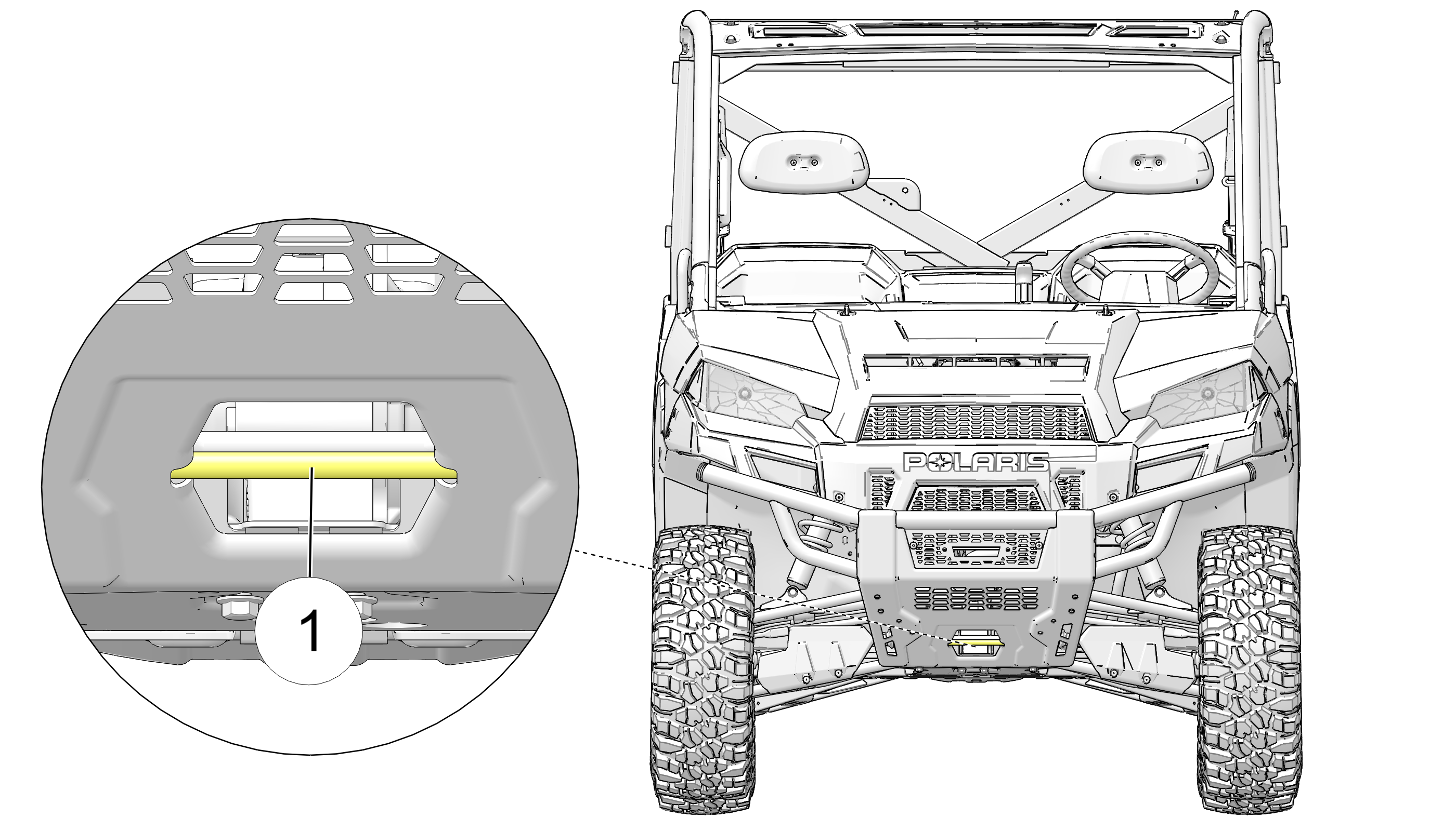
1 Front tie-down point
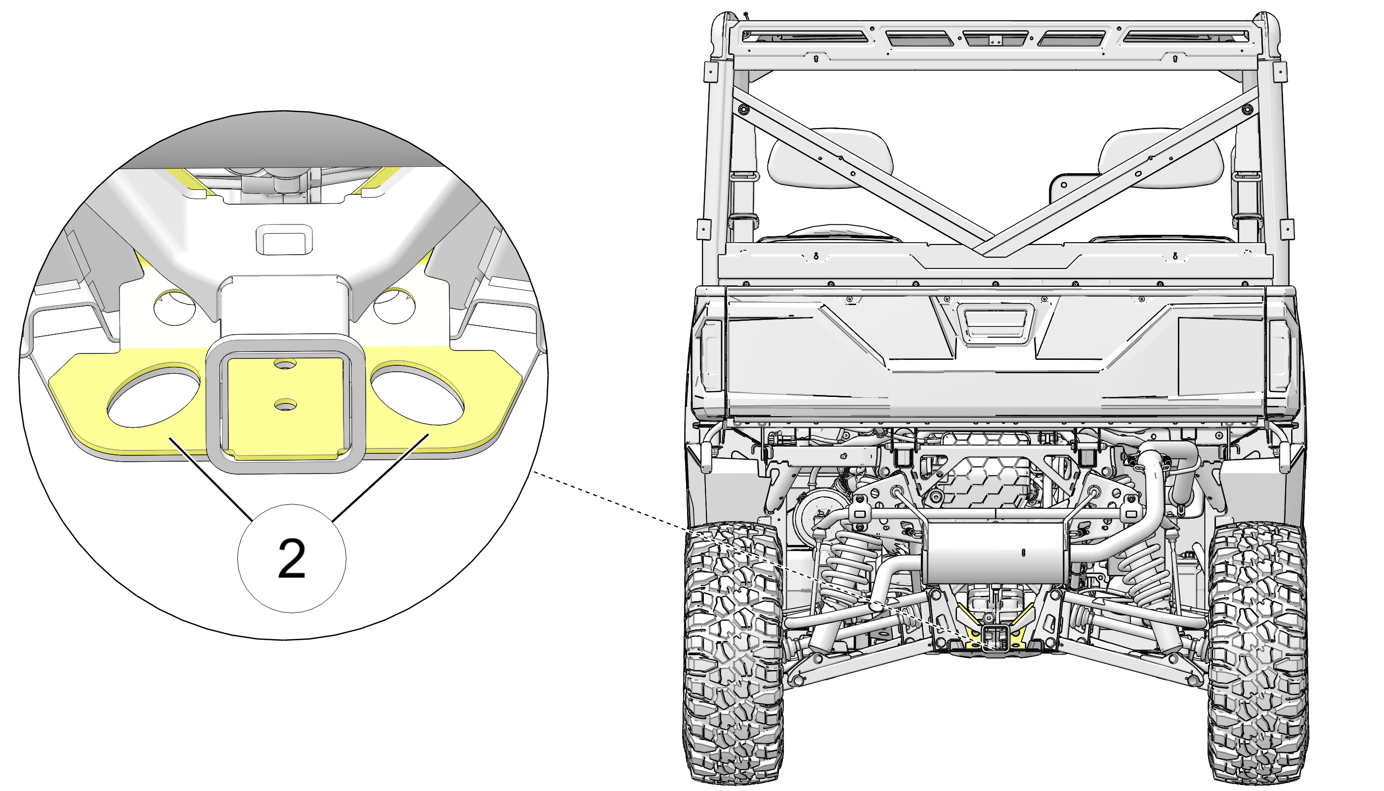
2 Rear tie-down points
| Polaris PRO XD Standard Cab Diesel | |
|---|---|
|
Maximum Weight Capacity |
1900 lb (862 kg) (including operator, passenger, cargo, accessories) |
|
Dry Weight |
1605 lb (728 kg) |
|
GVWR – Gross Vehicle Weight Rating |
3600 lb (1633 kg) per ANSI/OPEI B71.9-2016, Section 5.1.2 |
|
Fuel Capacity |
11.5 gal (43.5 l) |
|
Engine Oil Capacity |
3.9 qt (3.7 l) |
|
Coolant Capacity |
5.8 qt (5.5 l) |
|
Towing Capacity |
2500 lb (1134 kg) |
|
Hitch Tongue Capacity |
250 lb (113 kg) |
|
Max. Cargo Box Load |
1250 lb (567 kg) |
|
Overall Length |
126 in (320 cm) |
|
Overall Width |
62.5 in (158.8 cm) |
|
Overall Height |
75 in (191 cm) |
|
Wheelbase |
85 in (215.9 cm) |
|
Cargo Box Dimensions (Inside) |
54 in (137 cm) wide, 43.5 in (110 cm) long, 11.5 in (29 cm) high |
|
Ground Clearance |
11 in (27.9 cm) |
|
Min. Turning Radius |
112 in (284.5 cm) |
|
Engine |
Kubota® liquid-cooled 3 cylinder diesel |
|
Displacement |
898 cc |
|
Bore x Stroke |
72 mm x 73.6mm |
|
Alternator Output |
12V DC 140A |
|
Compression Ratio |
22.8:1 |
|
Starting System |
Electric |
|
Fuel System |
Mechanical fuel injection |
|
Front Suspension |
Dual A-arm w/9 in (22.86 cm) of travel |
|
Rear Suspension |
Independent w/9 in (22.86 cm) of travel |
|
Lubrication System |
Full pressure with full flow filter |
|
Driving System Type |
PVT, 4-wheel independent shaft, lockable differential |
|
Shift Type |
Single Lever (H/L/N/R/P) |
|
Tire Size - Front |
26 x 10 - 12 |
|
Tire Size - Rear |
26 x 10 - 12 |
|
Tire Pressure - Front |
24 psi (165 kpa) |
|
Tire Pressure - Rear |
24 psi (165 kpa) |
|
Brakes, Front/Rear |
Foot Activated, 4 wheel hydraulic disc |
|
Hood Headlight |
2 single beam, 50W, quartz/halogen |
|
Taillights |
10 L.E.D. (.28W) |
|
Brake Light |
10 L.E.D. (3.1W) |
| Polaris PRO XD Crew Cab Diesel | |
|---|---|
|
Maximum Weight Capacity |
2075 lb (941 kg) (including operator, passengers, cargo, accessories) |
|
Dry Weight |
1862 lb (845 kg) |
|
GVWR – Gross Vehicle Weight Rating |
4000 lb (1814 kg) per ANSI/OPEI B71.9-2016, Section 5.1.2 |
|
Fuel Capacity |
11.5 gal (43.5 l) |
|
Engine Oil Capacity |
3.9 qt (3.7 l) |
|
Coolant Capacity |
6.6 qt (6.25 l) |
|
Towing Capacity |
2500 lb (1134 kg) |
|
Hitch Tongue Capacity |
250 lb (113 kg) |
|
Max. Cargo Box Load |
1250 lb (567 kg) |
|
Overall Length |
157 in (399 cm) |
|
Overall Width |
62.5 in (158.8 cm) |
|
Overall Height |
75 in (191 cm) |
|
Wheelbase |
117 in (297 cm) |
|
Cargo Box Dimensions (Inside) |
54 in (137 cm) wide, 43.5 in (110 cm) long, 11.5 in (29 cm) high |
|
Ground Clearance |
11 in (27.9 cm) |
|
Min. Turning Radius |
154 in (391.2 cm) |
|
Engine |
Kubota® liquid-cooled 3 cylinder diesel |
|
Displacement |
898 cc |
|
Bore x Stroke |
72 mm x 73.6mm |
|
Alternator Output |
12V DC 140A |
|
Compression Ratio |
22.8:1 |
|
Starting System |
Electric |
|
Fuel System |
Mechanical fuel injection |
|
Front Suspension |
Dual A-arm w/9 in (22.86 cm) of travel |
|
Rear Suspension |
Independent w/9 in (22.86 cm) of travel |
|
Lubrication System |
Full pressure with full flow filter |
|
Driving System Type |
PVT, 4-wheel independent shaft, lockable differential |
|
Shift Type |
Single Lever (H/L/N/R/P) |
|
Tire Size - Front |
26 x 10 - 12 |
|
Tire Size - Rear |
26 x 10 - 12 |
|
Tire Pressure - Front |
24 psi (165 kpa) |
|
Tire Pressure - Rear |
24 psi (165 kpa) |
|
Brakes, Front/Rear |
Foot Activated, 4 wheel hydraulic disc |
|
Hood Headlight |
2 single beam, 50W, quartz/halogen |
|
Taillights |
10 L.E.D. (.28W) |
|
Brake Light |
10 L.E.D. (3.1W) |
|
Product |
Size (quantity) |
Quantity |
Part Number |
|---|---|---|---|
|
Summer Diesel Oil 15W-40 (+5 °F to +104 °F) (-15 °C to +40 °C) |
1 qt (0.95 l) |
1 |
2882515 |
|
Synthetic Diesel Oil 5W-40 (-25 °F to +80 °F) (-31 °C to +27 °C) |
1 qt (0.95 l) |
1 |
2879832 |
|
1 gal (3.8 l) |
1 |
2881083 |
|
|
AGL |
1 qt (0.95 l) |
12 |
2878068 |
|
1 gal (3.8 l) |
4 |
2878069 |
|
|
Pump for Gallon Jug |
— |
1 |
2870465 |
|
Demand Drive |
1 qt (0.95 l) |
12 |
2877922 |
|
2.5 gal (9.5 l) |
2 |
2877923 |
|
|
Antifreeze / Coolant |
1 qt (0.95 l) |
12 |
2880514 |
|
1 gal (3.8 l) |
6 |
2880513 |
|
|
Grease Gun Kit, Premium All Season |
— |
1 |
2871312 |
|
All Season Grease |
Four 3 floz (89 ml) packs |
6 |
2871322 |
|
14 floz (414 ml) cartridge |
1 |
2871423 |
|
|
Premium Starter Grease |
— |
1 |
2871460 |
|
U-Joint Grease |
3 floz (89 ml) tube |
24 |
2871515 |
|
14 floz (414 ml) cartridge |
1 |
2871551 |
|
|
Dielectric Grease (Nyogel®) |
— |
1 |
2871329 |
|
Carbon Clean |
12 floz (355 ml) bottle |
12 |
2871326 |
|
Fuel Stabilizer |
16 floz (473 ml) |
12 |
2870652 |
|
2.5 gal (9.5 l) |
2 |
2872280 |
|
|
DOT 4 Brake Fluid |
— |
1 |
2872189 |
|
Loctite® 565 Thread Sealant |
— |
1 |
2871956 |
|
BatteryMINDer® 2012 AGM - 2 AMP Charger |
— |
1 |
2830438 |
| Possible Cause | Solution |
|---|---|
| Driving onto a pickup or tall trailer in high range | Use low range during loading. |
| Starting out going up a steep incline | Use low range. |
| Driving at low RPM or ground speed 3–7 mph (4.8–11.3 kph) | Drive at a higher speed or use low range more frequently. |
| Insufficient warm-up at low ambient temperatures | Warm the engine at least 5 minutes. With the transmission in neutral, advance the throttle to about 1/8 throttle in short bursts, 5 to 7 times. The belt will become more flexible and prevent belt burning. |
| Slow/easy clutch engagement | Use the throttle quickly and effectively. |
| Towing/pushing at low RPM/low ground speed | Use low range only. |
| Utility use/plowing | Use low range only. |
| Stuck in mud or snow | Shift the transmission to low range and carefully use fast,
aggressive throttle application to engage clutch. WARNING: Excessive throttle may cause loss of control and vehicle rollover. |
| Climbing over large objects from a stopped position | Shift the transmission to low range and carefully use fast,
brief, aggressive throttle application to engage clutch. WARNING: Excessive throttle may cause loss of control and vehicle rollover. |
| Belt slippage from water or snow ingestion into the PVT system | Dry out the PVT. Prevent water from entering the PVT intake duct. See Intake Pre-Filters for more information. Inspect clutch seals for damage if repeated leaking occurs. |
| Clutch malfunction | An authorized dealer can assist. |
| Poor engine performance | Check for clogged air filter, clogged fuel filter, water in the fuel or foreign material in fuel tank or fuel lines. An authorized dealer can assist. |
| Slippage from failure to warm up belt | Always warm up the belt by operating below 30 mph (48 kph) for 1 mi (1.6 km) (5 mi (8 km) or more when temperature is below freezing). |
| Wrong or missing belt | Install the recommended belt. |
| Improper break-in | Always break in a new belt and/or clutch. |
| Possible Cause | Solution |
|---|---|
| Low battery voltage | Recharge the battery to 12.8 VDC |
| Loose battery connections | Check all connections and tighten |
| Loose electronic control box connections | Inspect, clean, reinstall connectors |
| Possible Cause | Solution |
|---|---|
|
Out of fuel |
Refuel |
|
Clogged fuel filter/water separator |
Replace |
|
Clogged air filter |
Replace |
|
Water is present in fuel |
Drain the fuel system and refuel, replace fuel filter/ water separator |
|
Old or non-recommended fuel |
Replace with fresh recommended fuel |
|
Water or fuel in crankcase |
Immediately see your POLARIS dealer |
|
Low battery voltage |
Recharge the battery to 12.8 VDC |
|
Mechanical failure |
See your dealer |
|
Defective glow plug |
Inspect and replace |
|
Defective stop solenoid |
Replace |
|
Defective fuel pump |
Replace |
| Possible Cause | Solution |
|---|---|
|
Poor fuel quality or incorrect fuel |
Replace with recommended fuel |
|
Low fuel level |
Refuel |
|
Clogged fuel filter |
Replace |
|
Clogged air filter |
Replace |
|
Loose ignition connections |
Check all connections and tighten |
|
Water present in fuel |
Replace with new fuel |
|
Kinked or plugged fuel tank vent line |
Inspect and replace |
|
Other mechanical failure |
Your dealer can assist |
| Possible Cause | Solution |
|---|---|
|
Poor fuel quality or incorrect fuel |
Replace with recommended fuel |
|
Clogged fuel filter |
Replace |
|
Clogged air filter |
Replace |
|
Loose ignition connections |
Check all connections and tighten |
|
Water present in fuel |
Replace with new fuel |
|
Kinked or plugged fuel tank vent line |
Inspect and replace |
|
Other mechanical failure |
See your dealer |
|
Out of fuel |
Refuel |
|
Low battery voltage |
Recharge the battery to 12.8 VDC |
|
Overheated engine |
Clean radiator screen and core, clean engine exterior, operate at lower load, see your dealer |
POLARIS Inc., 2100 Highway 55, Medina, MN 55340 (POLARIS) gives a TWO YEAR LIMITED WARRANTY on all components of your POLARIS vehicle against defects in material or workmanship. POLARIS further warrants that the spark arrester in this product will meet the efficiency requirements of USFS standard 5100-1C for at least 1000 hours when subjected to normal use and when maintenance and installation are in accordance with POLARIS recommendations.
This warranty covers parts and labor charges for repair or replacement of defective parts and begins on the date of purchase by the original retail purchaser. This warranty is transferable to another owner during the warranty period through a POLARIS dealer, but any such transfer will not extend the original term of the warranty. The duration of this warranty may vary by international region based upon local laws and regulations.
At the time of sale, the Warranty Registration Form must be completed by your dealer and submitted to POLARIS within ten days of purchase. Upon receipt of this registration, POLARIS will record the registration for warranty. No verification of registration will be sent to the purchaser as the copy of the Warranty Registration Form will be your proof of warranty coverage. If you have not signed the original registration and received the customer copy, please contact your dealer immediately. NO WARRANTY COVERAGE WILL BE ALLOWED UNLESS YOUR VEHICLE IS REGISTERED WITH POLARIS. Initial dealer preparation and set-up of your vehicle is very important in ensuring trouble-free operation. Purchasing a machine in the crate or without proper dealer set-up will void your warranty coverage.
This POLARIS limited warranty excludes any failures that are not caused by a defect in material or workmanship. THIS WARRANTY DOES NOT COVER CLAIMS OF DEFECTIVE DESIGN. This warranty also does not cover acts of God, accidental damage, normal wear and tear, abuse or improper handling. This warranty also does not cover any vehicle, component, or part that has been altered structurally, modified, neglected, improperly maintained or used for racing, competition or purposes other than for which it was designed.
This warranty excludes damages or failures resulting from improper lubrication; improper engine timing; improper fuel; surface imperfections caused by external stress, heat, cold or contamination; operator error or abuse; improper component alignment, tension, adjustment or altitude compensation; snow, water, dirt or other foreign substance ingestion/contamination; improper maintenance; modified components; use of aftermarket or unapproved components, accessories, or attachments; use of unapproved software or calibration; unauthorized repairs; or repairs made after the warranty period expires or by an unauthorized repair center.
This warranty excludes damages or failures caused by abuse, accident, fire, or any other cause other than a defect in materials or workmanship and provides no coverage for consumable components, general wear items, or any parts exposed to friction surfaces, stresses, environmental conditions and/or contamination for which they were not designed or not intended, including but not limited to the following items:
Wheels and tires
Suspension components
Brake components
Seat components
Clutches and components
Steering components
Batteries
Light bulbs/Sealed beam lamps
Filters
Lubricants
Bushings
Finished and unfinished surfaces
Carburetor/Throttle body components
Engine components
Drive belts
Hydraulic components and fluids
Circuit breakers/Fuses
Electronic components
Spark plugs
Sealants
Coolants
Bearings
Mixing oil brands or using non-recommended oil may cause engine damage. We recommend the use of POLARIS engine oil.
Damage or failure resulting from the use of non-recommended lubricants or fluids is not covered by this warranty.
This warranty provides no coverage for personal loss or expense, including mileage, transportation costs, hotels, meals, shipping or handling fees, product pick-up or delivery, replacement rentals, loss of product use, loss of profits, or loss of vacation or personal time.
THE EXCLUSIVE REMEDY FOR BREACH OF THIS WARRANTY SHALL BE, AT POLARIS' OPTION, REPAIR OR REPLACEMENT OF ANY DEFECTIVE MATERIALS, COMPONENTS, OR PRODUCTS. THE REMEDIES SET FORTH IN THIS WARRANTY ARE THE ONLY REMEDIES AVAILABLE TO ANY PERSON FOR BREACH OF THIS WARRANTY. POLARIS SHALL HAVE NO LIABILITY TO ANY PERSON FOR INCIDENTAL, CONSEQUENTIAL OR SPECIAL DAMAGES OF ANY DESCRIPTION, WHETHER ARISING OUT OF EXPRESS OR IMPLIED WARRANTY OR ANY OTHER CONTRACT, NEGLIGENCE, OR OTHER TORT OR OTHERWISE. THIS EXCLUSION OF CONSEQUENTIAL, INCIDENTAL, AND SPECIAL DAMAGES IS INDEPENDENT FROM AND SHALL SURVIVE ANY FINDING THAT THE EXCLUSIVE REMEDY FAILED OF ITS ESSENTIAL PURPOSE.
THE IMPLIED WARRANTY OF FITNESS FOR A PARTICULAR PURPOSE IS EXCLUDED FROM THIS LIMITED WARRANTY. ALL OTHER IMPLIED WARRANTIES (INCLUDING BUT NOT LIMITED TO THE IMPLIED WARRANTY OF MERCHANTABILITY) ARE LIMITED IN DURATION TO THE ABOVE ONE YEAR WARRANTY PERIOD. POLARIS DISCLAIMS ALL EXPRESS WARRANTIES NOT STATED IN THIS WARRANTY. SOME STATES DO NOT PERMIT THE EXCLUSION OR LIMITATION OF INCIDENTAL OR CONSEQUENTIAL DAMAGES OR ALLOW LIMITATIONS ON THE DURATION OF IMPLIED WARRANTIES, SO THE ABOVE LIMITATIONS MAY NOT APPLY TO YOU IF INCONSISTENT WITH CONTROLLING STATE LAW.
If your vehicle requires warranty service, you must take it to a POLARIS Servicing Dealer. When requesting warranty service you must present your copy of the Warranty Registration Form to the dealer. (THE COST OF TRANSPORTATION TO AND FROM THE DEALER IS YOUR RESPONSIBILITY.) POLARIS suggests that you use your original selling dealer; however, you may use any POLARIS Servicing Dealer to perform warranty service.
Warranty or Service Bulletin repairs must be done by an authorized POLARIS dealer, or other qualified person. If you move or are traveling within the country where your product was purchased, Warranty and Service Bulletin repairs may be requested from any authorized POLARIS dealer, or other qualified person, that sells the same line as your product.
If you are traveling temporarily outside the country where your product was purchased, you should take your product to an authorized POLARIS dealer, or other qualified person. You must show the dealer photo identification from the country of the selling dealer's authorized location as proof of residence. Upon residence verification, the servicing dealer will be authorized to perform the warranty repair.
If you move to another country, be sure to contact POLARIS Customer Assistance and the customs department of the destination country before you move. Product importation rules vary considerably from country to country. You may be required to present documentation of your move to POLARIS in order to continue your warranty coverage. You may also be required to obtain documentation from POLARIS in order to register your product in your new country. You should warranty register your product at a local POLARIS dealer in your new country immediately after you move to continue your warranty coverage and to ensure that you receive information and notices regarding your product.
If you purchase a POLARIS product from a private party, to be kept and used outside of the country in which the product was originally purchased, all warranty coverage will be denied. You must nonetheless register your product under your name and address with a local POLARIS dealer in your country to ensure that you receive safety information and notices regarding your product.
EXCEPT WHERE SPECIFICALLY REQUIRED BY LAW, THERE IS NO WARRANTY OR SERVICE BULLETIN COVERAGE ON THIS PRODUCT IF IT IS SOLD OUTSIDE THE COUNTRY OF THE SELLING DEALER'S AUTHORIZED LOCATION. This policy does not apply to products that have received authorization for export from POLARIS. Dealers may not give authorization for export. You should consult an authorized dealer to determine this product's warranty or service coverage if you have any questions. This policy does not apply to products registered to government officials or military personnel on assignment outside the country of the selling dealer's authorized location. This policy does not apply to Safety Bulletins.
If your product is registered outside of the country where it was purchased and you have not followed the procedure set above, your product will no longer be eligible for warranty or service bulletin coverage of any kind, other than safety recalls. Products registered to government officials or military personnel on assignment outside of the country where the product was purchased will continue to be covered by the Limited Warranty.
Please work with your dealer to resolve any warranty issues. Dealership contacts can be found via this website, if needed:
www.polaris.com/en-us/contact
Should your dealer require any additional assistance, they will contact the appropriate person at POLARIS.
This warranty gives you specific legal rights, and you may also have other rights which vary from state to state or in different countries. If any of the above terms are void because of federal, state, local law, all other warranty terms will remain in effect.
For questions call POLARIS Owner Connections:
United States & Canada: 1-800-POLARIS (1-800-765-2747)
French: 1-800-268-6334
To report a safety defect to Transport Canada, you may either fill
out an online defect complaint form at their website:
English: http://www.tc.gc.ca/recalls
French: http://www.tc.gc.ca/rappels
Or contact their Defect Investigations and Recalls Division by calling toll-free 1-800-333-0510 (Canada) or 819-994-3328 (Ottawa-Gatineau area / International).
The U.S. Environmental Protection Agency (EPA), the California Air Resources Board (CARB), and KUBOTA® Corporation (KUBOTA®) are pleased to explain the Federal and California Emission Control System Warranty on your non-road engine or marine engine. In California, new 2019 model year heavy duty off-road engines must be designed, built and equipped to meet California’s stringent anti-smog standards adopted by the Air Resources Board pursuant to its authority in Chapter 1 and 2, Part 5, Division 26 of the California Health and Safety Code. In other states of the U.S.A., new non-road engines subject to the provisions of 40 CFR 1039 subpart A and new marine engines subject to the provisions of 40 CFR 1042 subpart A must be designed, built and equipped, at the time of sale, to meet the U.S. EPA regulations.
KUBOTA® must warrant the emission control system on your Compression Ignition engine for the period of time listed below provided there has been no abuse, vandalism, neglect, improper maintenance or unapproved modifications to your engine. This emission warranty is applicable in all states of the U.S.A., its provinces and territories regardless of whether an individual state, province, or territory has enacted warranty provisions that differ from the Federal warranty provisions. This emission warranty is also applicable in all provinces and territories of CANADA.
Your emission control system may include parts such as the fuel injection system and the air induction system. Also included may be hoses, belts, connectors and other emission-related assemblies.
Where a warrantable condition exists, KUBOTA® will repair your engine at no cost to you, including diagnosis (if the diagnostic work is performed at an authorized dealer), parts and labor.
EMISSION DESIGN AND DEFECT WARRANTY COVERAGE
The emissions warranty period for the engine begins on the original date of sale to the initial purchaser and continues for each subsequent purchaser for the period mentioned below.
If any emission related part on your engine is defective, the part will be repaired or replaced by KUBOTA® free of charge.
1. For non-road engines
The emissions warranty period for all engines rated under 19kW (25 Hp) is 2000 hours of operation or two (2) years of use, whichever first occurs.
The emissions warranty period for constant speed engines rated under 37kW (50Hp) with rated speeds greater than or equal to 3000 rpm is 2000 hours of operation or two (2) years of use, whichever first occurs.
The emissions warranty period for all other engine not already listed is 3000 hours of operation or five (5) years of use, whichever first occurs.
2. For marine engines (commercial Category 1)
The emissions warranty period for all engines rated under 19kW (25 Hp) is 1500 hours of operation or two and a half (2.5) years of use, whichever first occurs.
The emissions warranty period for all engines rated at or above 19 kW (25 Hp) and under 37kW (50 Hp) is 2500 hours of operation or three and a half (3.5) years of use, whichever first occurs.
The emissions warranty period for all engines rated at or above 37kW (50 Hp) is 5000 hours of operation or five (5) years of use, whichever first occurs.
OWNER’S WARRANTY RESPONSIBILITIES
(a) As the engine owner, you are responsible for the performance of the required maintenance listed in your KUBOTA® operator’s manual. KUBOTA® recommends that you retain all receipts covering maintenance on your engine, but KUBOTA® cannot deny a warranty claim solely for the lack of receipts or for your failure to ensure the performance of all scheduled maintenance.
(b) As the engine owner, you should be aware, however, that KUBOTA® may deny your warranty coverage if your engine or a part has failed due to abuse, vandalism, neglect, improper maintenance or unapproved modifications.
(c) Your engine is designed to operate on Ultra Low Sulfur Diesel Fuel only. Use of any other fuel may result in your engine no longer operating in compliance with Federal or California’s emissions requirements.
(d) You are responsible for presenting your engine to the nearest dealer or service station authorized by KUBOTA® when a problem exists. The warranty repairs should be completed in a reasonable amount of time, not to exceed 30 days.
(e) If you have any questions regarding your warranty rights and responsibilities or the location of the nearest authorized dealer or distributor, you should contact:
KUBOTA® ENGINE AMERICA CORPORATION, Service Department at 1-800-532-9808, kea_g.eewri@kubota.com or KUBOTA® TRACTOR CORPORATION, National Service Department at 1-800-558-2682, KubotaEmissionsWarranty@kubota.com or KUBOTA® CANADA LTD at (905) 294-7477.
COVERAGE
KUBOTA® warrants to the initial purchaser and each subsequent purchaser that your engine will be designed, built and equipped, at the time of sale, to meet all applicable regulations. KUBOTA® also warrants to the initial purchaser and each subsequent purchaser that your engine shall be free from defects in materials and workmanship which cause the engine to fail to conform to applicable regulations for the period mentioned above from the original date of sale.
KUBOTA® shall remedy warranty defects at any authorized KUBOTA® engine dealer or warranty station. Any authorized work done at an authorized dealer or warranty station shall be free of charge to the owner if such work determines that a warranted part is defective. Any KUBOTA® approved or equivalent replacement part (including any KUBOTA® approved aftermarket part) may be used for any warranty maintenance or repairs on emission related parts, and must be provided free of charge to the owner if the part is still under warranty.
KUBOTA® is liable for damages to other engine components caused by the failure of a warranted part still under warranty. The use of replacement parts not equivalent to the original parts may impair the effectiveness of your engine emission control system. If such a replacement part is used in the repair or maintenance of your engine, and KUBOTA® determines it is defective or causes a failure of a warranted part, your claim for repair of your engine may be denied.
Listed below are the parts covered by the Federal and California Emission Control Systems Warranty. Some parts listed below may require scheduled maintenance and are warranted up to the first scheduled replacement point for that part. The warranted parts are (if applicable):
Air-Induction System
Intake Manifold
Turbocharger System
Charge Air Cooling System (Intercooler)
Catalyst or Thermal Reactor System
Catalytic converter
Exhaust manifold
Fuel Injection System
Fuel Supply Pump (Common Rail System)
Injector
Injection Pipe
Common Rail
Smoke Puff Limiter
Speed Timer
Cold Advance Timer
Injection Pump
Electronic Control System
ECU
Engine Speed / Timing Sensor
Accelerator Position Sensor
Coolant Temperature Sensor
Atmospheric Pressure Sensor
Intake Pressure Sensor
Intake Manifold Temperature Sensor
Intake Air Flow Sensor
Common Rail Pressure Sensor
Exhaust Gas Recirculation System
EGR Valve
EGR Cooler
EGR Valve Opening Rate Sensor
Particulate Controls
Any device used to capture particulate emissions.
Any device used in the regeneration of the particulate control device.
Control Device Enclosures and Manifolding
Diesel Particulate Filter Temperature Sensor
Differential Pressure Sensor
Advanced Oxides of Nitrogen (NOx) Controls
Selective Catalytic Reduction (SCR) Catalyst
Reductant (urea) Containers
Dispensing Systems
NOx Sensor
SCR Temperature Sensor
Any Sensor for Diesel Exhaust Fluid
Miscellaneous Items
Closed Breather System
Hoses*, Clamps*, Fittings, Tubing*
Gaskets, Seals
Kubota® supplied engine Wiring Harnesses
Kubota® supplied engine Elec. Connectors
Air Cleaner Element*, Fuel Filter Element*
Emission Control Information Labels
*Warranty period is equivalent to manufacturer's recommended first replacement interval as stated in the applicable model's operator's manual and/or service (workshop) manual.
MAINTENANCE REQUIREMENTS
The owner is responsible for the performance of the required maintenance as defined by KUBOTA® in the operator’s manual.
LIMITATIONS
This Emission Control System Warranty shall not cover any of the following;
(a) Repair or replacement required because of misuse or neglect, improper maintenance, repairs improperly performed or replacements not conforming to KUBOTA® specifications that adversely affect performance and/or durability, and alteration or modifications not recommended or approved in writing by KUBOTA®.
(b) Replacement of parts and other services and adjustments necessary for required maintenance at and after the first scheduled replacement point.
Certain POLARIS Off-Road Vehicles are available in 49-state and 50-state versions. Only the 50-state models are certified for sale in California. The 50-state models available for sale in California are identified by the letter “B” in the ninth position of the model number (e.g., R16RTE87B). The POLARIS 50-state models are designed and built with features such as a reduced cargo box capacity. Any modifications to these features may be a violation of the applicable California regulations and may void this limited emissions warranty offered by the manufacturer.
POLARIS Inc. warrants that at the time is first purchased, this
vehicle is:
Designed, built, and equipped so as to conform, at the time of sale, with all applicable California evaporative emissions regulations.
Free from defects in material and workmanship that may cause the failure of a warranted part as defined in California evaporative emissions regulations. All replacement parts must be identical in all material respects to that part as described in the OHRV manufacturer’s Executive Order of Certification application.
The California evaporative emissions control system limited warranty statement below applies to your Off Highway Recreational Vehicle in California if the vehicle is equipped with an evaporative emission control system and is labeled with a Vehicle Evaporative Emissions Control Information label indicating that the vehicle conforms to California evaporative emissions regulations applicable to new off-road sport vehicles, all-terrain vehicles, or off-road utility vehicles. These vehicles are referred to as “OHRV-EVAP” below.
|
CALIFORNIA EMISSION CONTROL WARRANTY STATEMENT YOUR WARRANTY RIGHTS AND OBLIGATIONS |
The California Air Resources Board and Polaris Industries Inc. are pleased to explain the emission control system warranty on your model year 2018 and newer Off Highway Recreational Vehicle. In California, new off-highway recreational vehicles must be designed, built and equipped to meet the State's stringent anti-smog standards. Polaris must warrant the emission control system on your OHRV-EVAP for the periods of time listed below provided there has been no abuse, neglect or improper maintenance of your OHRV-EVAP.
Your emission control system may include parts such as the carburetor or fuel injection system, fuel tank, fuel hoses, carbon canister, engine computer and Evaporative Emissions Control System parts listed in the U.S.A. EPA Emissions Limited Warranty. Also included may be hoses, belts, connectors and other emission-related assemblies. Where a warrantable condition exists, Polaris will repair your OHRV-EVAP at no cost to you including diagnosis, parts and labor.
MANUFACTURER’S WARRANTY COVERAGE:
For model year 2018 and newer OHRV-EVAP models.
For 30 months, or 2500 mi (4023 km), or 250 hours, whichever comes first, except for evaporative components over the OHRV high-priced warranty value, which is covered for 60 months, or 5000 mi (8047 km), or 500 hours, whichever comes first.
If any emission-related part on your OHRV-EVAP is defective, the part will be repaired or replaced by Polaris.
|
OWNER'S WARRANTY RESPONSIBILITIES: As the OHRV-EVAP owner, you are responsible for the performance of the required maintenance listed in your owner's manual. Polaris recommends that you retain all receipts covering maintenance on your OHRV-EVAP, but Polaris cannot deny warranty solely for the lack of receipts or for your failure to ensure the performance of a scheduled maintenance. As an owner you are responsible for presenting your OHRV-EVAP to a Polaris dealer as soon as a problem exists. The warranty repairs should be completed in a reasonable amount of time, not to exceed 30 days. As an OHRV-EVAP owner, you should also be aware that Polaris may deny you warranty coverage if your OHRV-EVAP or a part has failed due to abuse, neglect, improper maintenance or unapproved modifications. |
ADD-ON OR MODIFIED PARTS
An add-on or modified part must be compliant with applicable CARB emission control standards. A violation of this requirement is punishable by civil and/or criminal punishment.
| If you have any questions regarding your warranty rights and responsibilities, you should contact Polaris Customer Assistance at 1-800-POLARIS (1-800-765-2747) or the California Air Resources Board at 9528 Telstar Avenue, El Monte, CA 91731. |
United States & Canada: 1-800-POLARIS (1-800-765-2747)
French: 1-800-268-6334
Use the following chart to record periodic maintenance.
| DATE | MILES (KM) or HOURS |
TECHNICIAN | SERVICE PERFORMED / COMMENTS |
|---|---|---|---|
Was this helpful?