Drive Responsibly. This vehicle
has higher ground clearance and other features to handle rugged terrain.
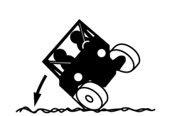
It can be overturned in situations where some other vehicles may not.
Abrupt maneuvers or aggressive driving, even on flat, open areas,
can cause loss of control, rollovers, severe injury or death. To avoid
loss of control and rollovers:

-
Avoid abrupt maneuvers, sideways sliding, skidding, or fishtailing,
and never do donuts.
-
Slow down before entering turn.
-
Avoid hard acceleration when turning, even from a stop.
High speed off-road operation
Driving off-road
vehicles to test the limits of your skills or abilities can be very
dangerous to you, passengers, and bystanders. Basic skills for driving
a car, ATV, or other off-road vehicles do not equip drivers to safely
attempt high speed off-road operation. Develop your skill gradually
through training, practice, and experience with the various driving
modes of this vehicle and the terrain in which you are operating.
Always do a low speed reconnaissance run (prerun) to become aware
of anything you may encounter.
High speed off-road operation can lead to loss of control, crashes,
or hard landings that can seriously injure occupants (even without
rolling the vehicle or damaging it).
If you plan on using the vehicle for high speed, off-road competition,
additional safety equipment may be necessary. Check the rules that
apply to your competition.
Do not go over jumps — going airborne can lead to serious
injury or death. Going airborne can cause loss of control, rollovers,
or crashing into the ground and may damage the vehicle. Even without
crashing, landings can be hard enough to cause any vehicle suspension
to fully compress (e.g., bottom out). Serious injuries, including
spinal injuries, can occur even if riders are properly harnessed,
wearing helmets and the vehicle is not damaged and remains upright.
You may encounter slopes, "jumps", or other terrain features that
could send the vehicle airborne, depending on your speed. These may
be defectively designed, poorly maintained, or not suitable for this
vehicle. Slow down, use extra care, and avoid going airborne. Never
take this vehicle over jumps.
Watching someone else go over a jump or go airborne does not mean
you can safely do so. Polaris cannot determine whether any jump you
may encounter is appropriate for this vehicle. Any jump, even a small
one, could be poorly maintained, designed, or not suitable for this
vehicle and may cause serious injury or death.
Plan for hills, rough terrain, ruts, and other changes in traction
and terrain. Proceed slowly and with extra care on unfamiliar
terrain. Avoid paved surfaces. Sudden changes in terrain such as holes,
depressions, banks, softer or harder ground, or other irregularities
may cause loss of control or rollover. Give yourself time to react
to rocks, bumps, or holes that may be hard to see. Operating in deep
snow or tall grass may make it harder to see obstacles.
If you cannot go around an obstacle, such as a fallen tree or a
ditch, stop the vehicle in a safe place. Get out to inspect the area
thoroughly. Look from both your approach side and exit side. If you
are reasonably confident you can continue safely, choose the path
that will allow you to go straight over the obstacle to minimize the
vehicle tipping sideways. Go only fast enough to maintain your momentum,
but still give yourself plenty of time to react to changes in conditions.
If there is any question about your ability to maneuver safely over
the obstacle, you should turn around if the ground is flat and you
have the room, or back up until you find a less difficult path.
Abrupt application of the accelerator pedal can cause the tires
to lose traction, reducing control of the vehicle and increasing the
possibility of an accident, especially while on sloped terrain or
while crossing obstacles such as rocks or logs.
Avoid Operating on Public Roads (Paved or Otherwise). This
vehicle does not have highway safety features that on-road vehicles
may have (air bags, anti-lock brakes, stability control, etc.). If
another vehicle collides with you, the likelihood of a serious injury
or death may be greater. Also, you may not be able to avoid a crash
or rollover if you make sudden or abrupt maneuvers such as swerving
or emergency braking.
While it may be legal locally to drive on some public roads in
specific parts of the country, your vehicle was not designed or certified
as an on-road motor vehicle. Polaris does not support public road
use except as may be necessary to cross roads designated for connecting
off highway vehicle trail segments. If you must drive on-road, drive
slowly and defensively. Your vehicle may lack the features needed
to comply with state or local laws that permit limited public road
use. Modifications you make to your vehicle to meet these requirements
may void the vehicle warranty. In addition, refer to tire manufacturer’s
instructions or limitations for on-road operation, including speed
limits and premature tire wear.
Improperly operating on hills can cause loss of control, rollover,
or accident, which can lead to serious injury or death. Use extra
care when operating on hills. Plan for rough terrain, ruts, and other
changes in traction and terrain.
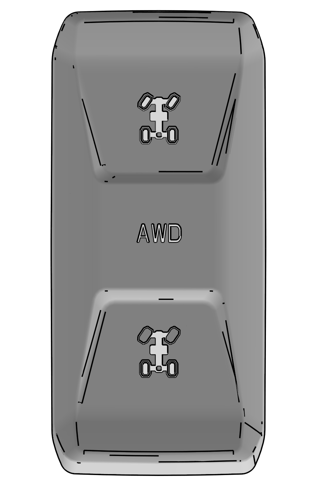
Driving up hills
Check the terrain before
ascending a hill and make sure it is not too slippery or loose. Engage
all-wheel drive for hills. Drive straight uphill, keeping speed and
throttle steady. Avoid steep hills which can cause the vehicle to
overturn.
Recovering from stalling on a hill
If the
vehicle loses forward speed, apply the brakes gradually and stop.
Do not attempt to turn the vehicle around. Instead, shift to reverse
and allow the vehicle to slowly roll straight downhill. Apply light
brake pressure to control speed.
Overtopping a hill
Slow down when you reach
the crest of a hill. Never blindly go over the crest of a hill or
a drop off at high speed. An obstacle, a sharp drop, or another vehicle
or person could be on the other side of the hill.
Driving down hills
Check the terrain before
descending a hill and make sure it is not too slippery or loose. Engage
all-wheel drive and proceed slowly, applying the brakes lightly. Never
descend a hill with the transmission in neutral or if the engine is
turned off.
Avoid side hilling (riding across slopes)
If unavoidable, proceed slowly and with extra caution. Avoid obstacles
and changes in terrain that could cause the vehicle to tip or slide.
If it feels like the vehicle begins to tip or slide, immediately turn
downhill.
Riding near wooded areas or brush
Use extra
caution when operating near trees, particularly when operating on
narrow trails. Tree branches or brush can be driven into the cab striking
or stabbing occupants.
Riding in snow
Always keep the brake and
accelerator pedals free of snow and ice. Apply the brakes frequently
to prevent ice or snow accumulation on the brake pads which can reduce
brake performance.
Riding on ice
Never operate the vehicle on
a frozen body of water unless you have verified that the ice can support
the weight of the vehicle. Severe injury or death can result if the
vehicle falls through the ice.
Riding in water / Falling into water
Operating
through deep or fast-flowing water can cause loss of traction, loss
of control, overturning, or being swept away in water. You can be
seriously injured or killed from entrapment and drowning. Never operate
the vehicle in fast-flowing water or in water that exceeds the floor
level of the vehicle. Avoid sharp drop-offs and large rocks. Choose
a path that provides an entrance and exit point with gradual inclines.
Wet brakes may have reduced stopping ability. After leaving water,
test the brakes. Apply them lightly several times while driving slowly.
The friction will help dry out the pads.
Riding on sand dunes
Use extra caution when
operating on or near dunes. Be alert for changes in terrain. Never
blindly go over the crest of a hill or a drop-off at high speed. An
obstacle, a sharp drop, or another vehicle or a person could be on
the other side of the hill.
Riding in low-visibility conditions
Use extra
caution and drive slowly in conditions of reduced visibility such
as fog, rain, and darkness.
Plan ahead to avoid the need for evasive maneuvers, such as
swerving. Hitting an obstacle — including wildlife —
you are not ready for can be dangerous. Choosing to swerve instead
can be even more dangerous because it can lead to loss of control,
rollover, or collisions.
When operating in areas with possibility of wildlife appearing
in your path, plan ahead to avoid swerving for animals if doing so
could result in collisions or rollovers. Go slowly or avoid driving
during seasons or times of day when animals such as deer are more
likely to cross your path without warning.
Avoid Collisions With Other Vehicles
When
following another vehicle or operating in the same area as others,
keep a safe distance to avoid collisions. Allow extra space when sight
distances are limited by dust, snow, curves, hills, or other conditions.
Plan ahead to avoid having to swerve or leave the trail to avoid a
collision.
On trails, be prepared to make space for other vehicles to pass.
If you need to stop on a trail, move your vehicle to the edge of the
path to allow others to pass safely.
Correct a skid by turning the steering wheel in the direction
of the skid.
Never apply the brakes during a skid.
If the vehicle begins to slide downhill or you feel it may tip,
turn downhill immediately and stop. Maneuver slowly and carefully
until you can drive straight downhill.
Do not continue driving if your vehicle may be damaged or if
you were in a crash or rollover.
Operating the
vehicle while damaged or after a crash or rollover can cause loss
of control, rollover, or accident, which can lead to serious injury
or death. If you cannot safely transport the vehicle on your own,
contact a recovery and towing service.
After any crash, rollover, or other accident, have a POLARIS dealer
inspect the vehicle for possible damage, including seat belts, ROPS,
brakes, suspension, and steering systems.
Be prepared in case your vehicle becomes damaged or disabled, especially
in remote areas. Consider in advance how to get help and stay safe
until it arrives whenever you ride.
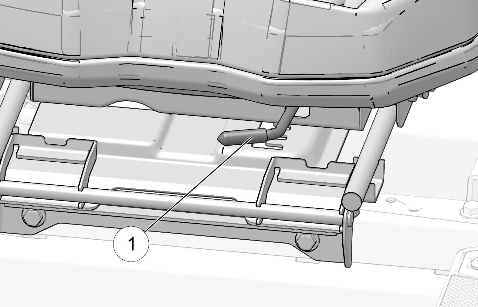
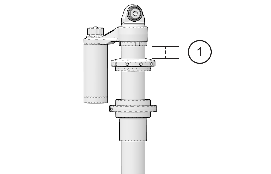
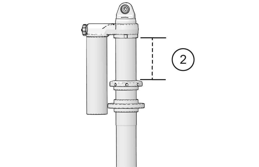
The vehicle does not have a tow hitch and is not designed to
tow another vehicle for any distance.
Towing can
alter vehicle handling and may cause loss of control.
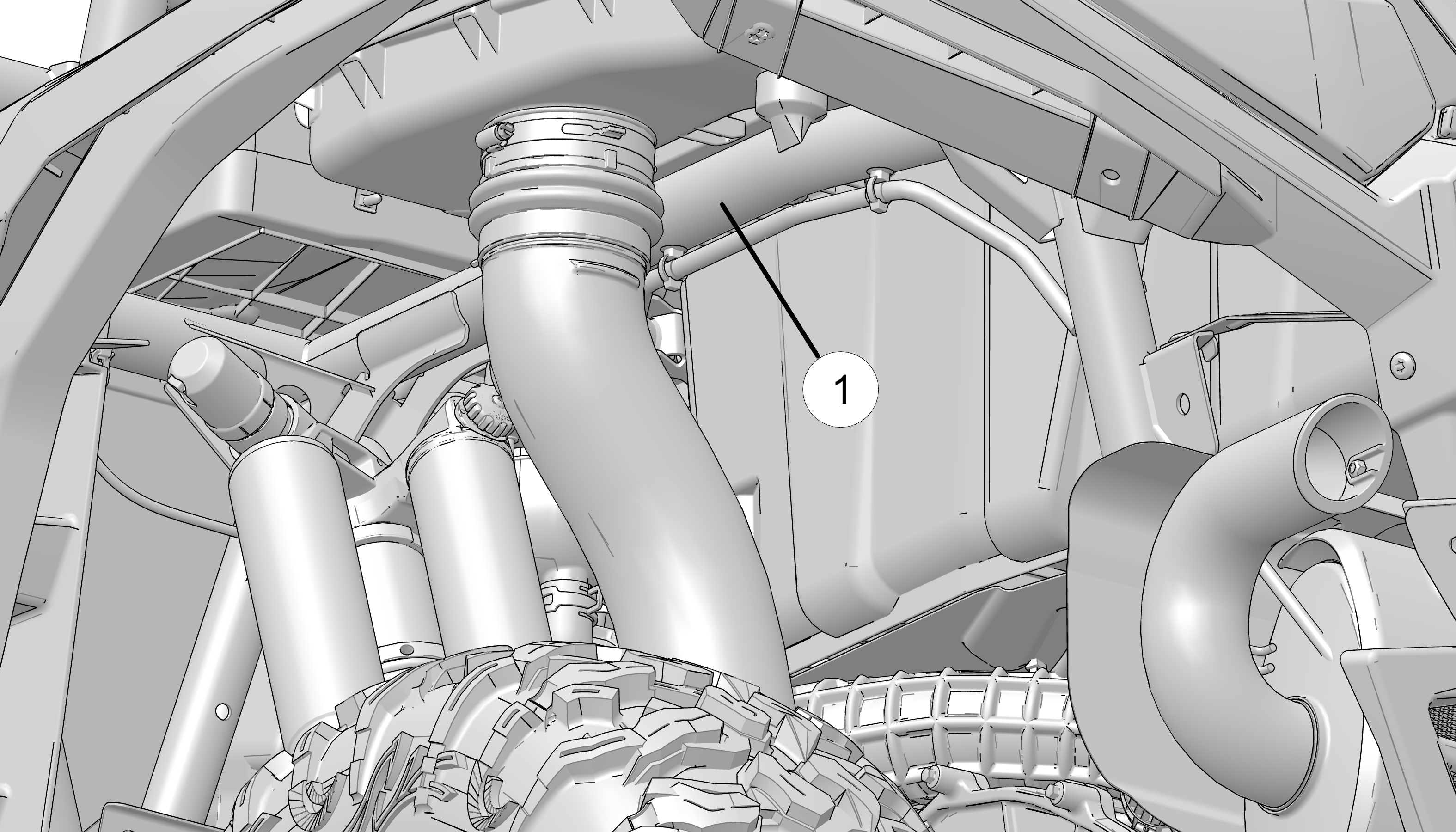
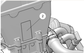
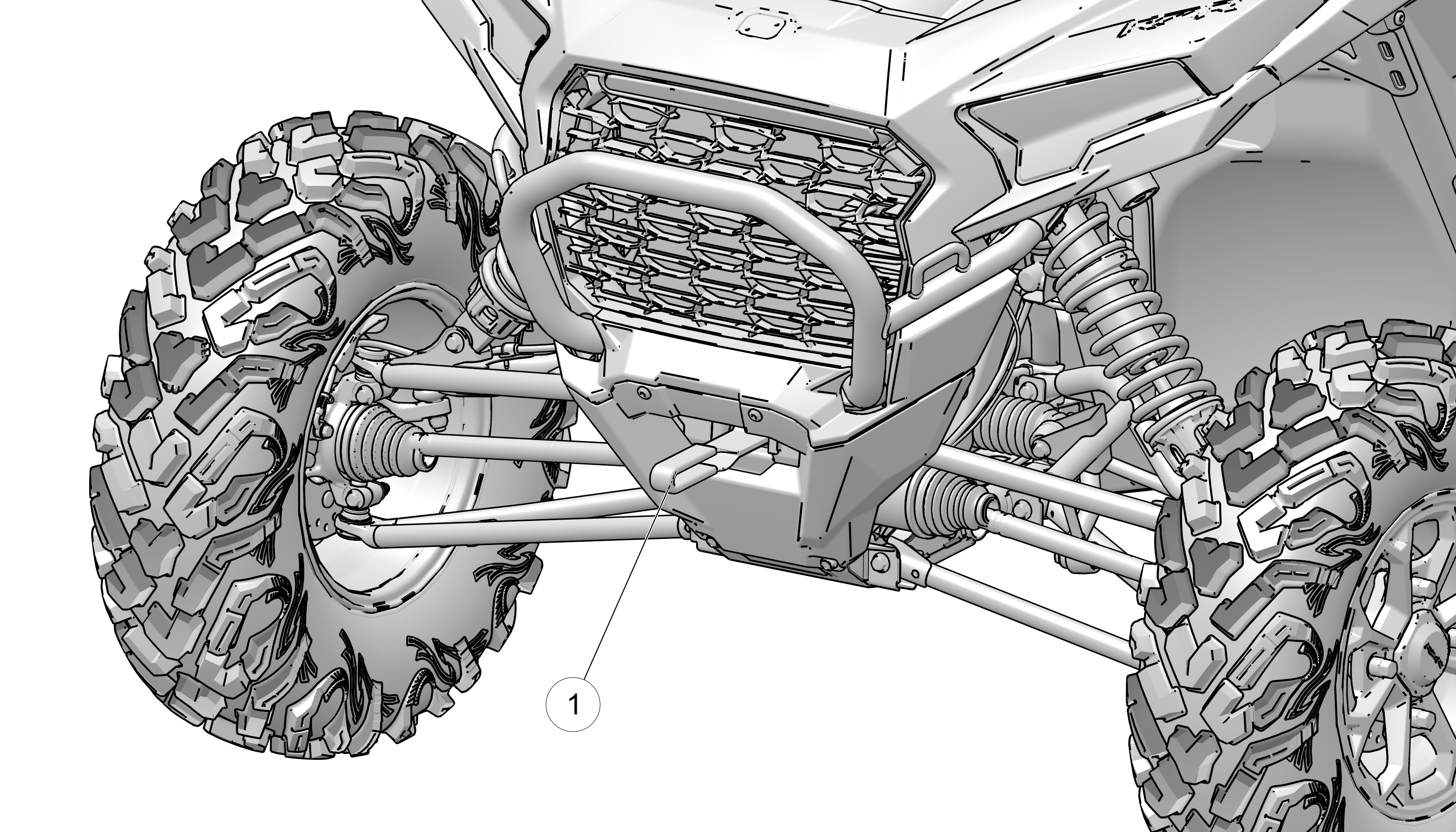
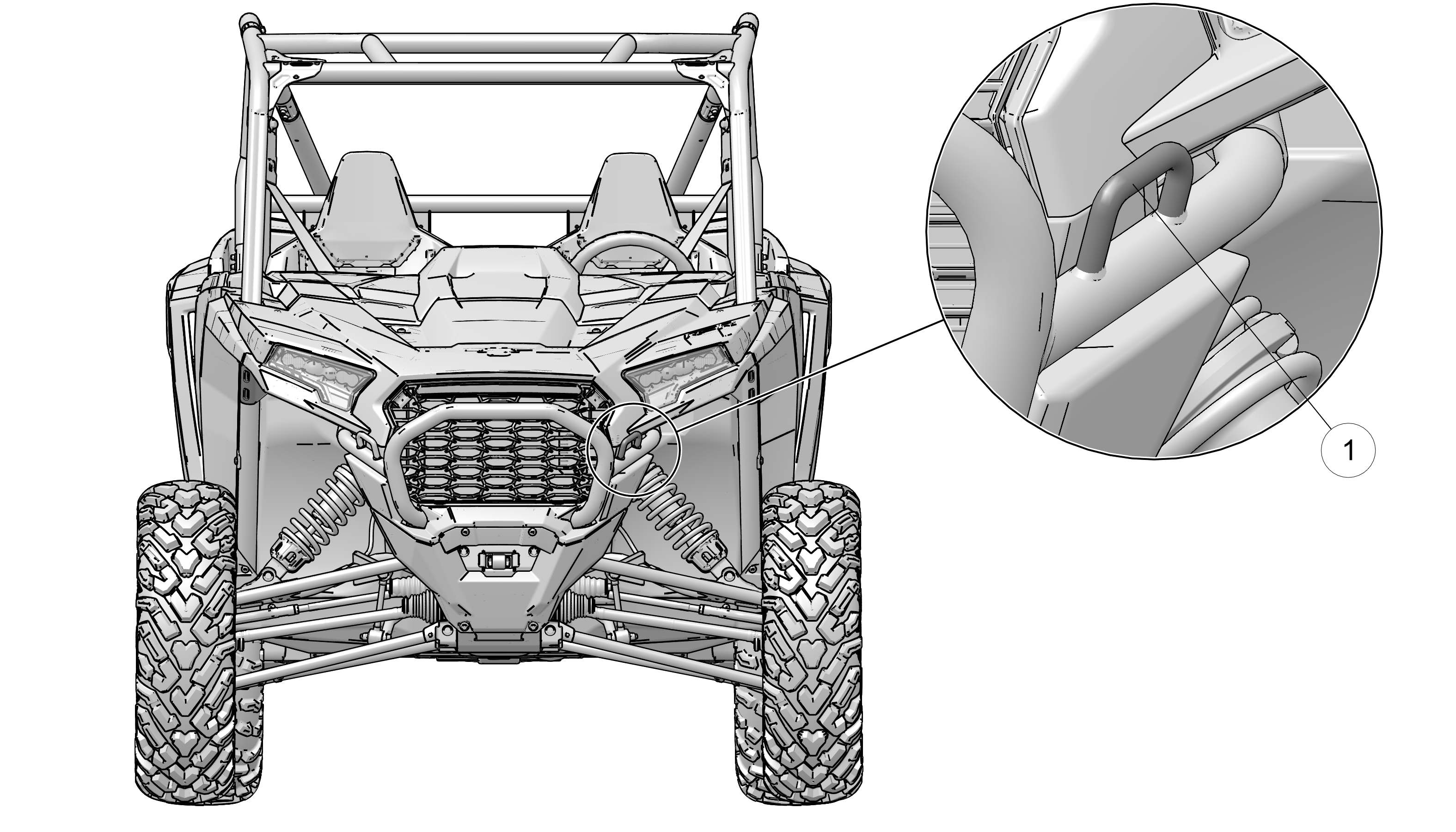
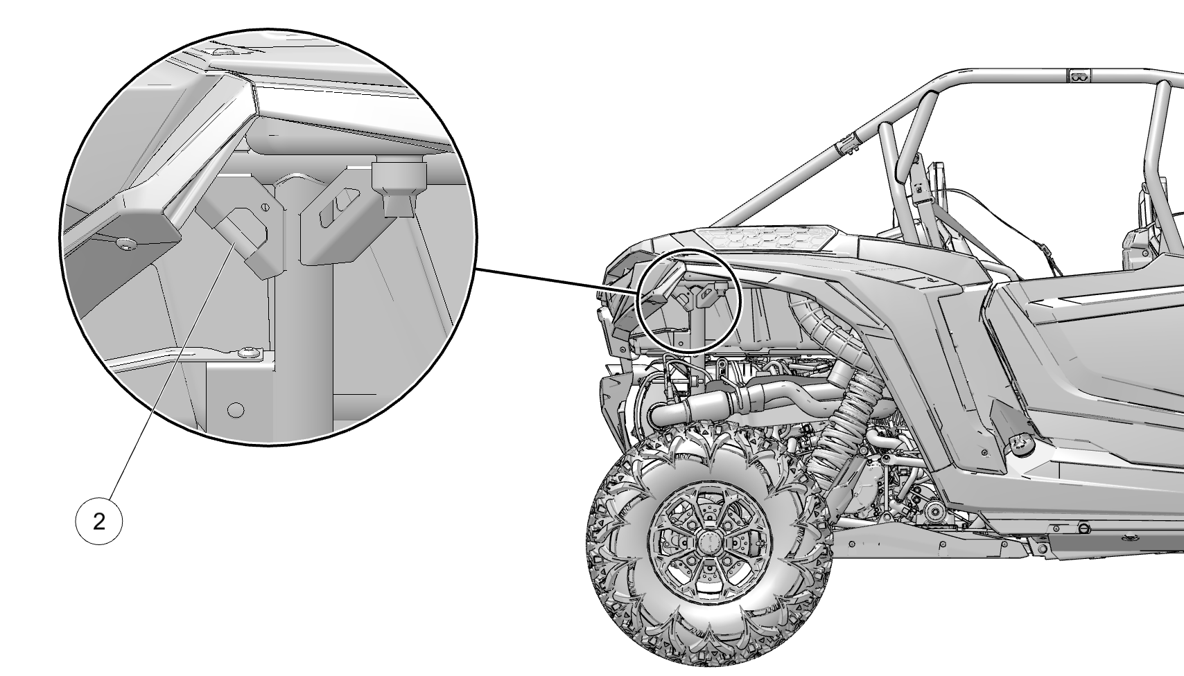
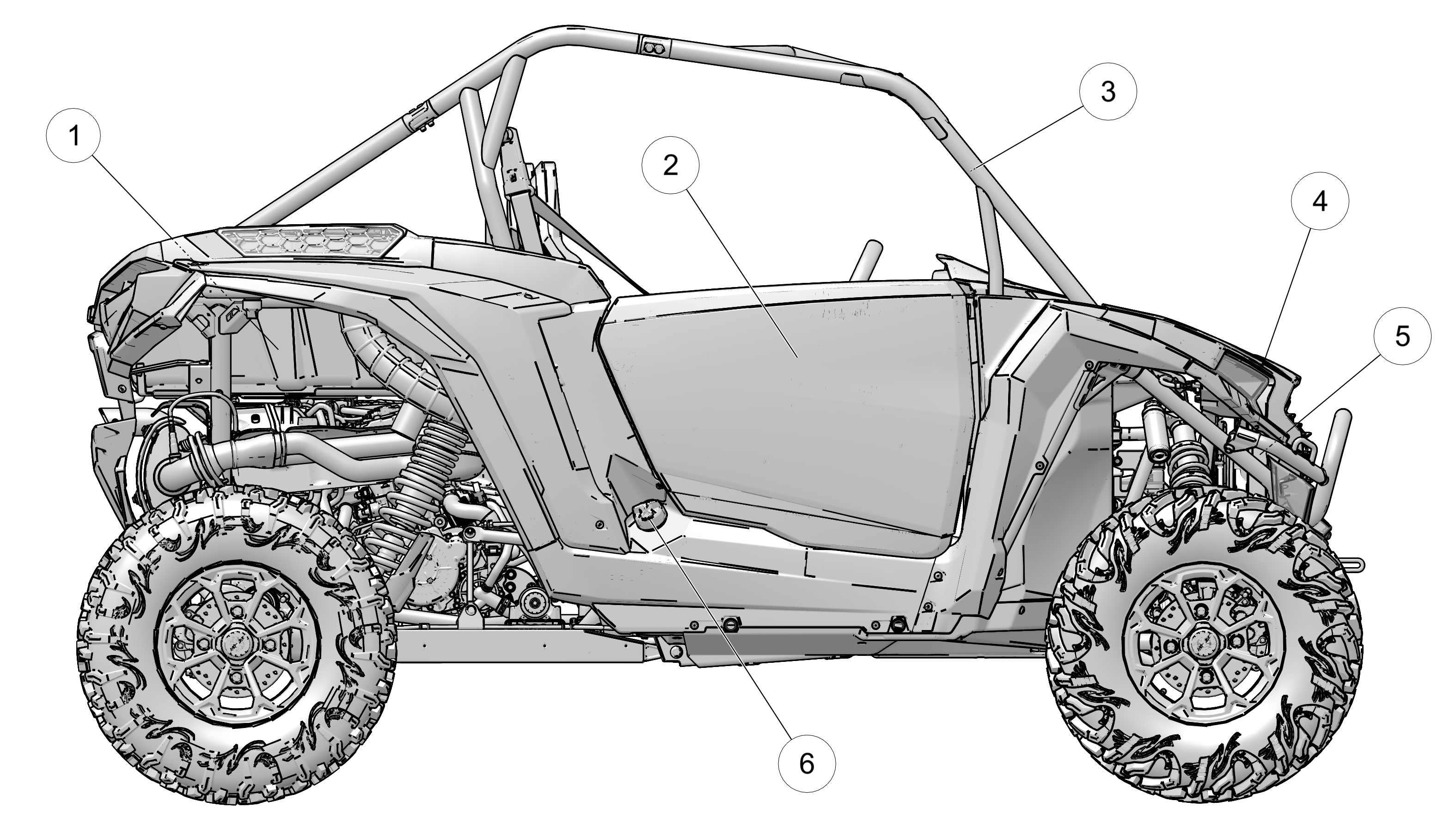
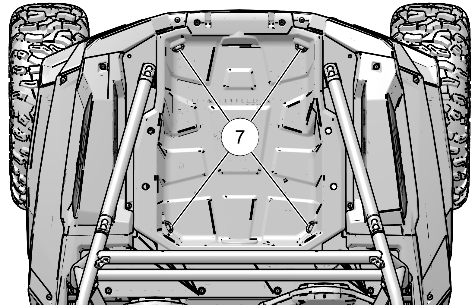
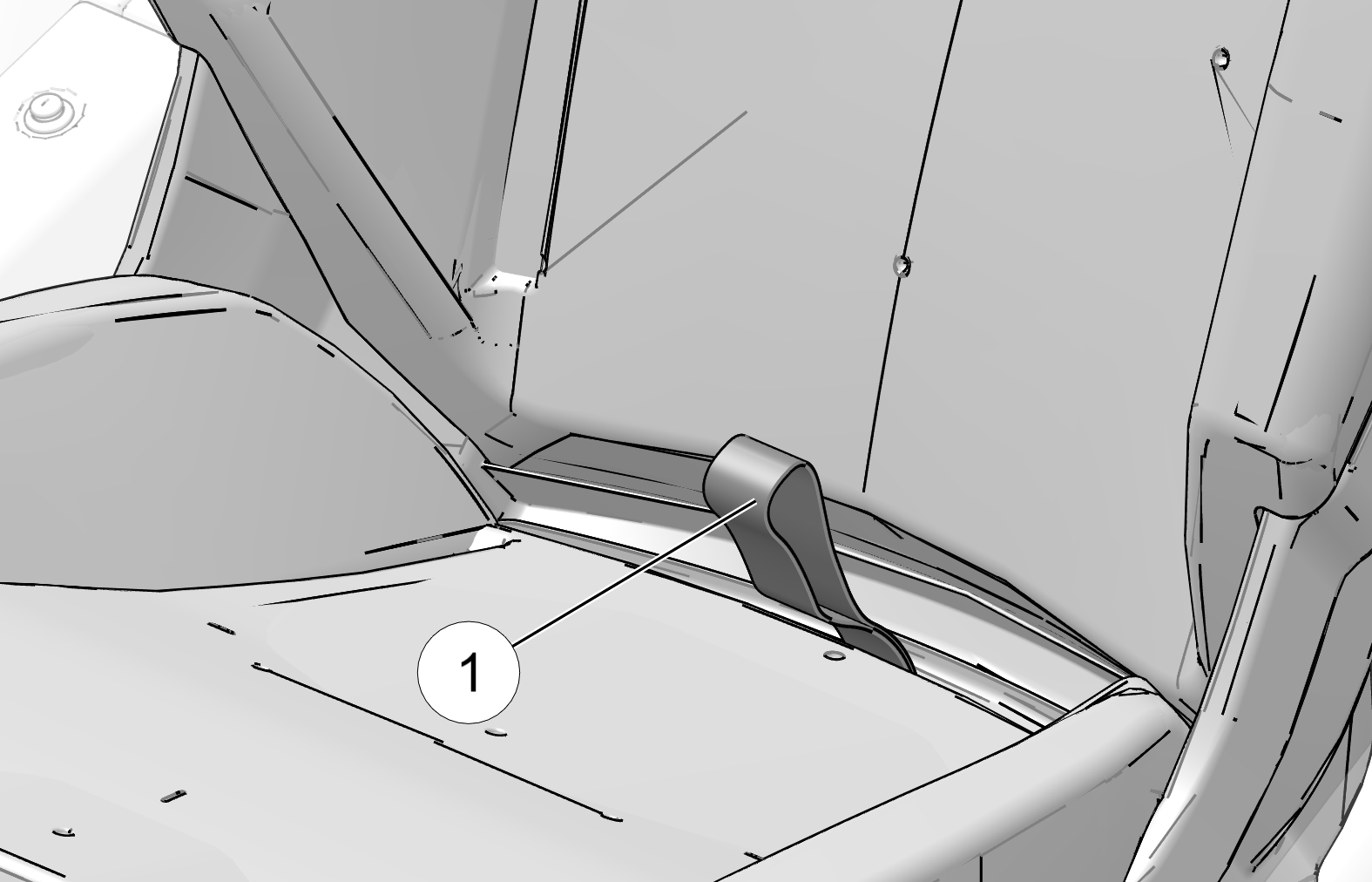
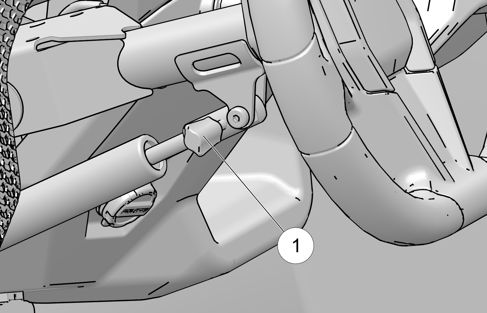
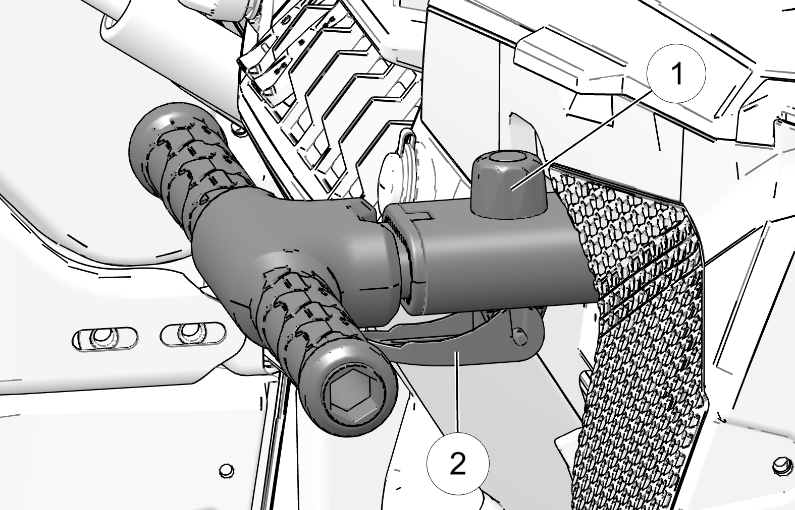
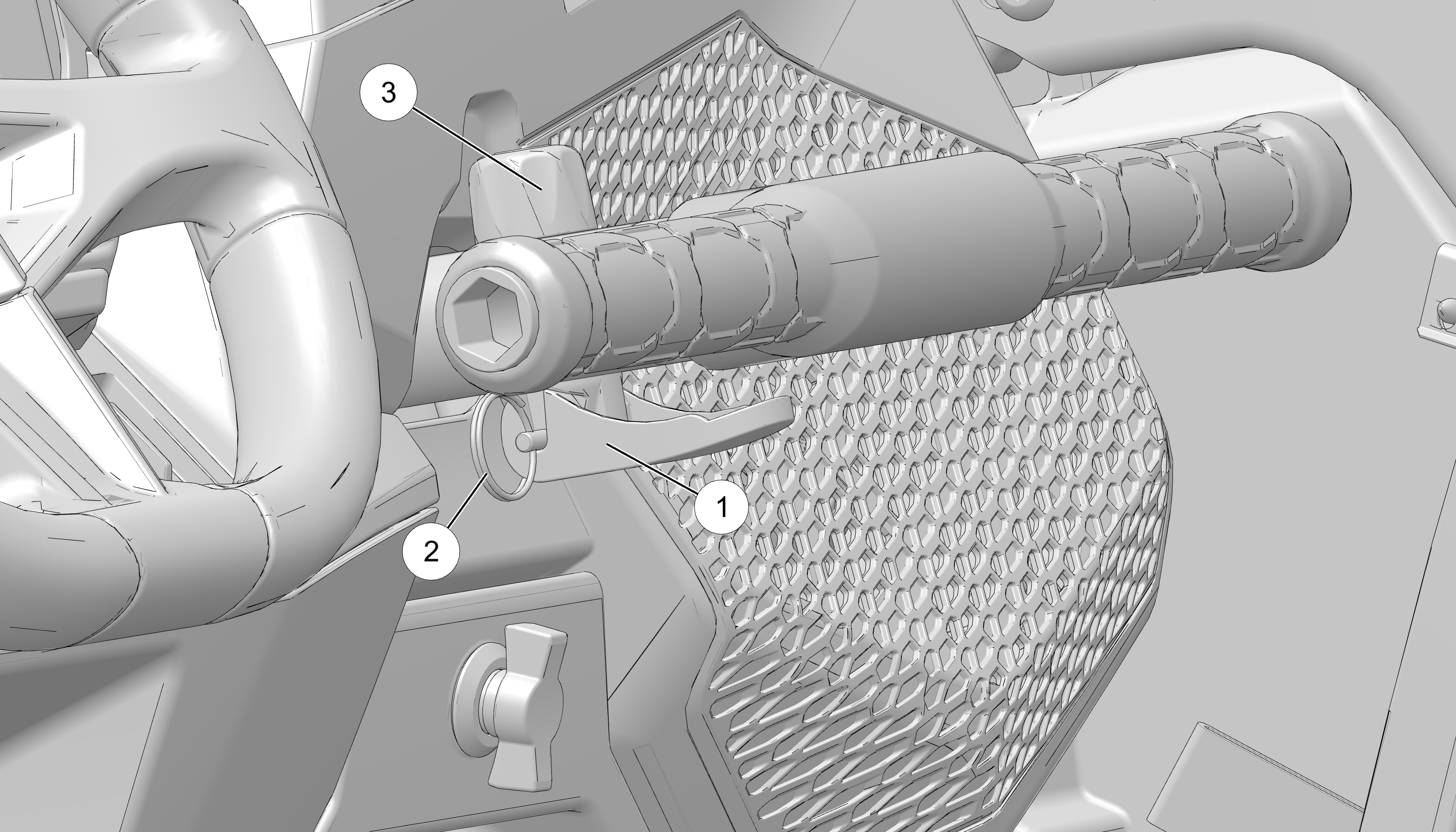
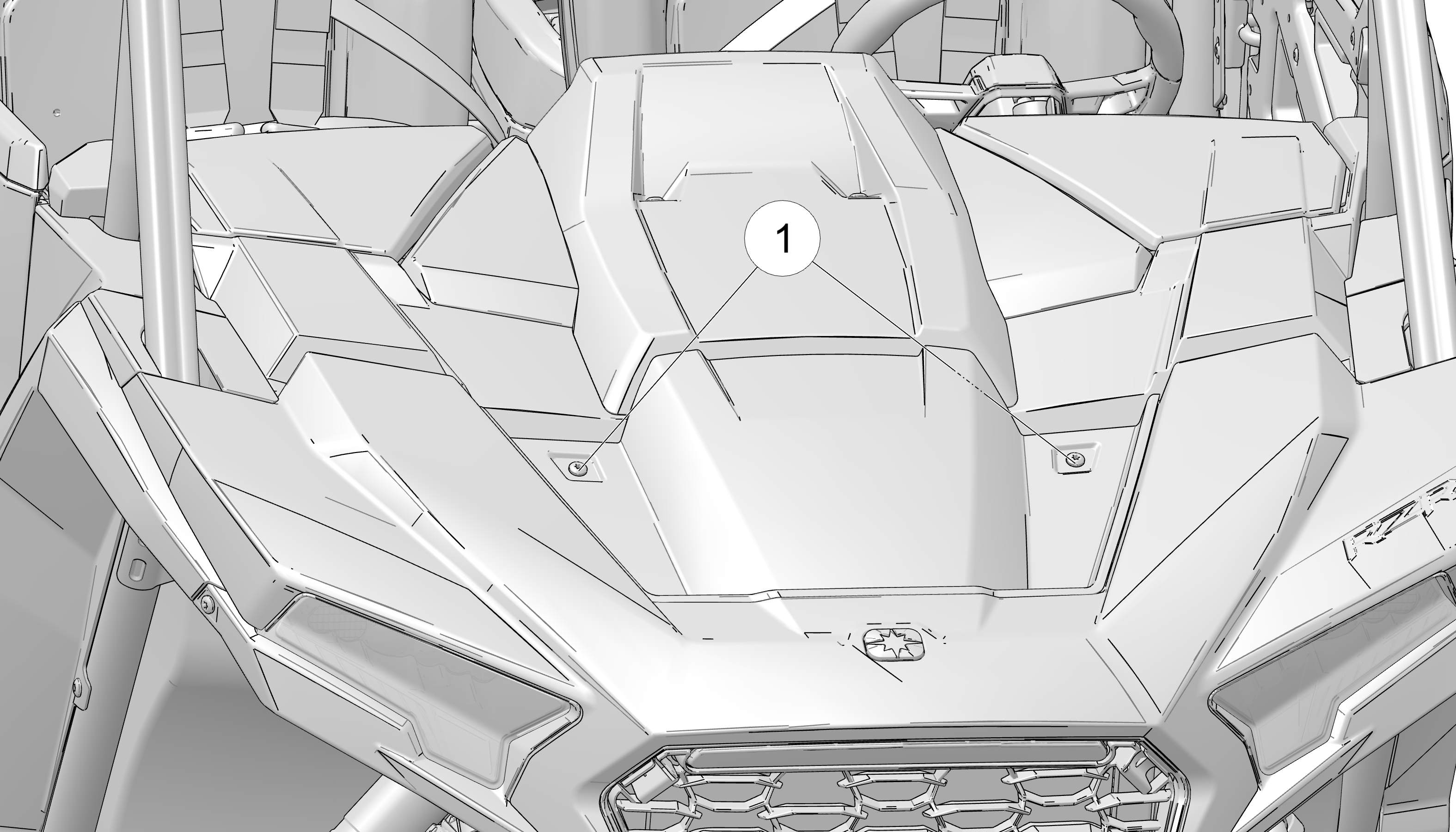
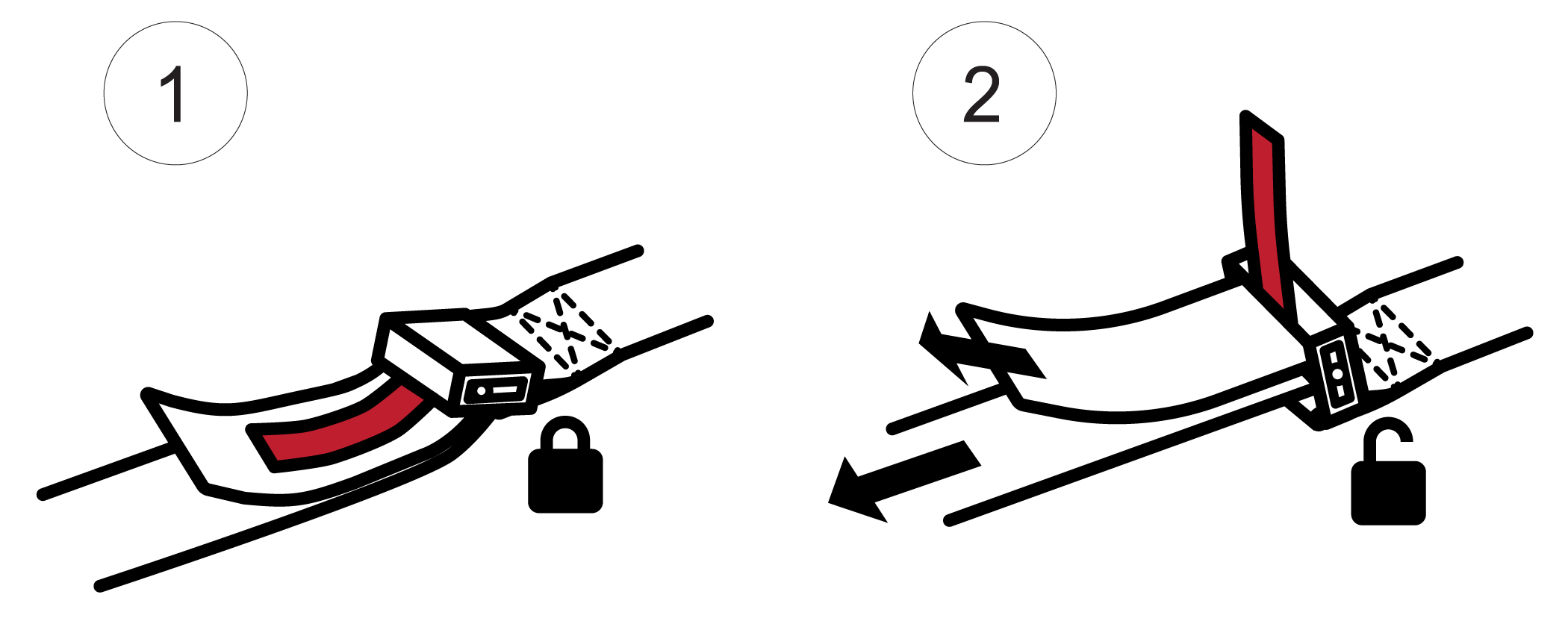
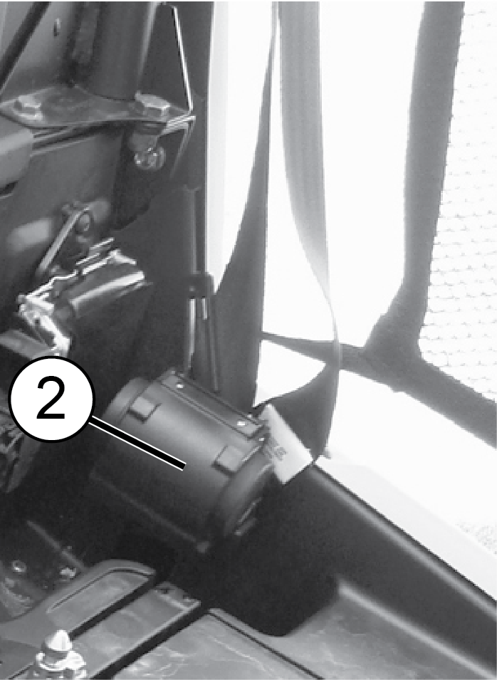
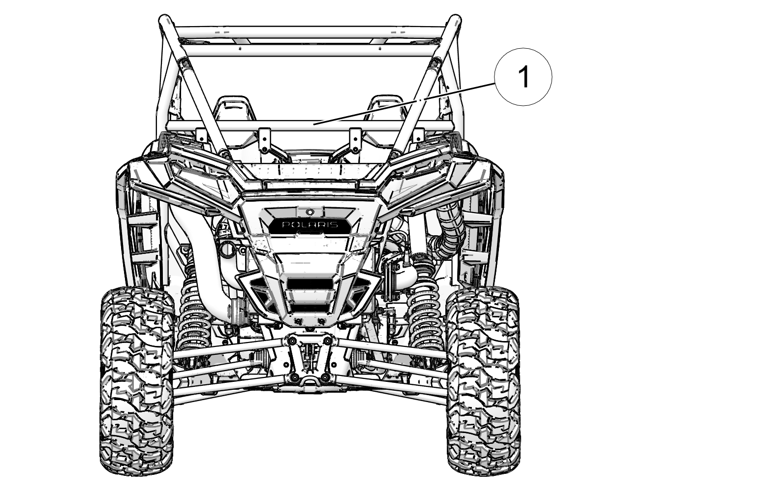
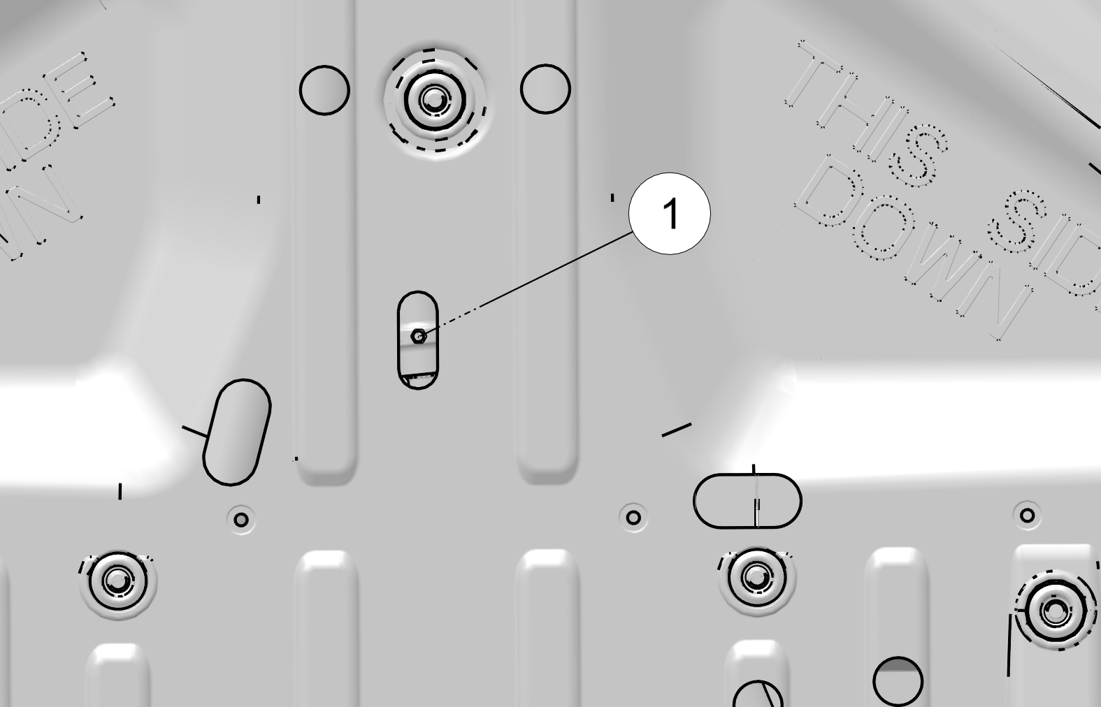
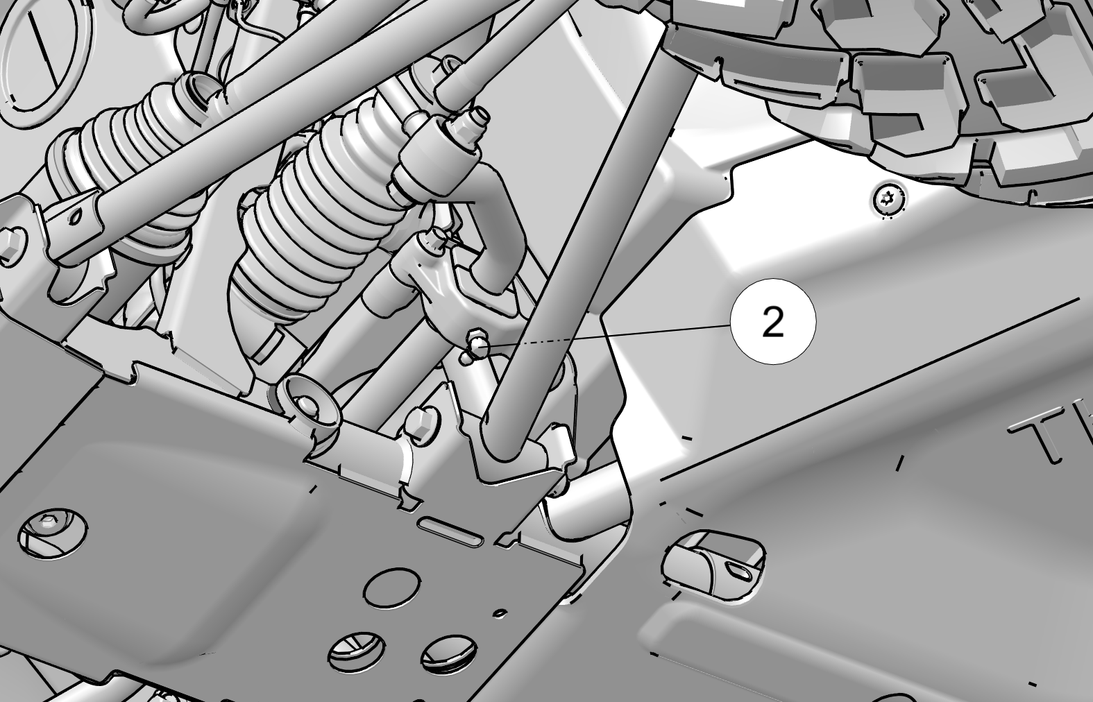
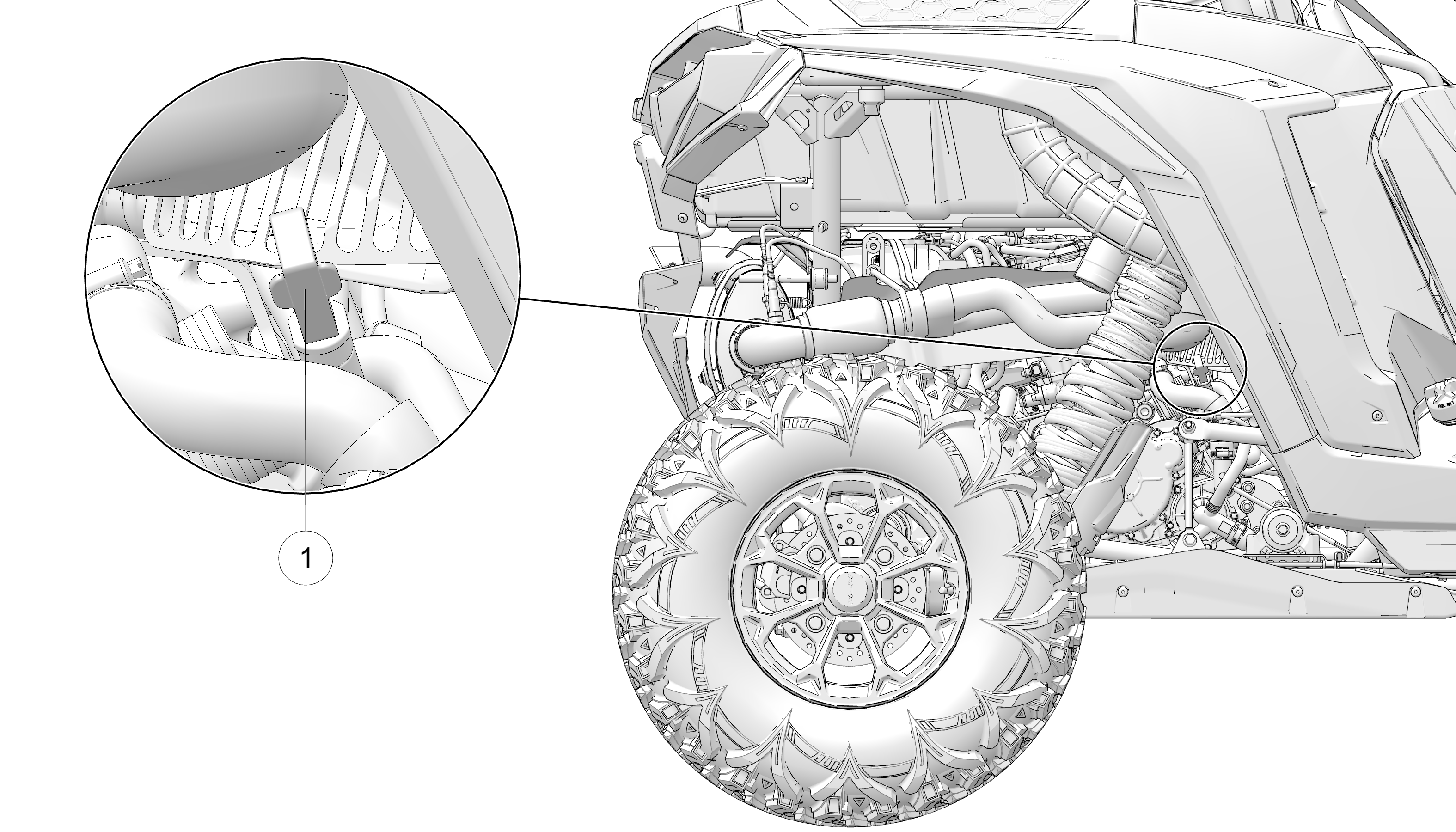
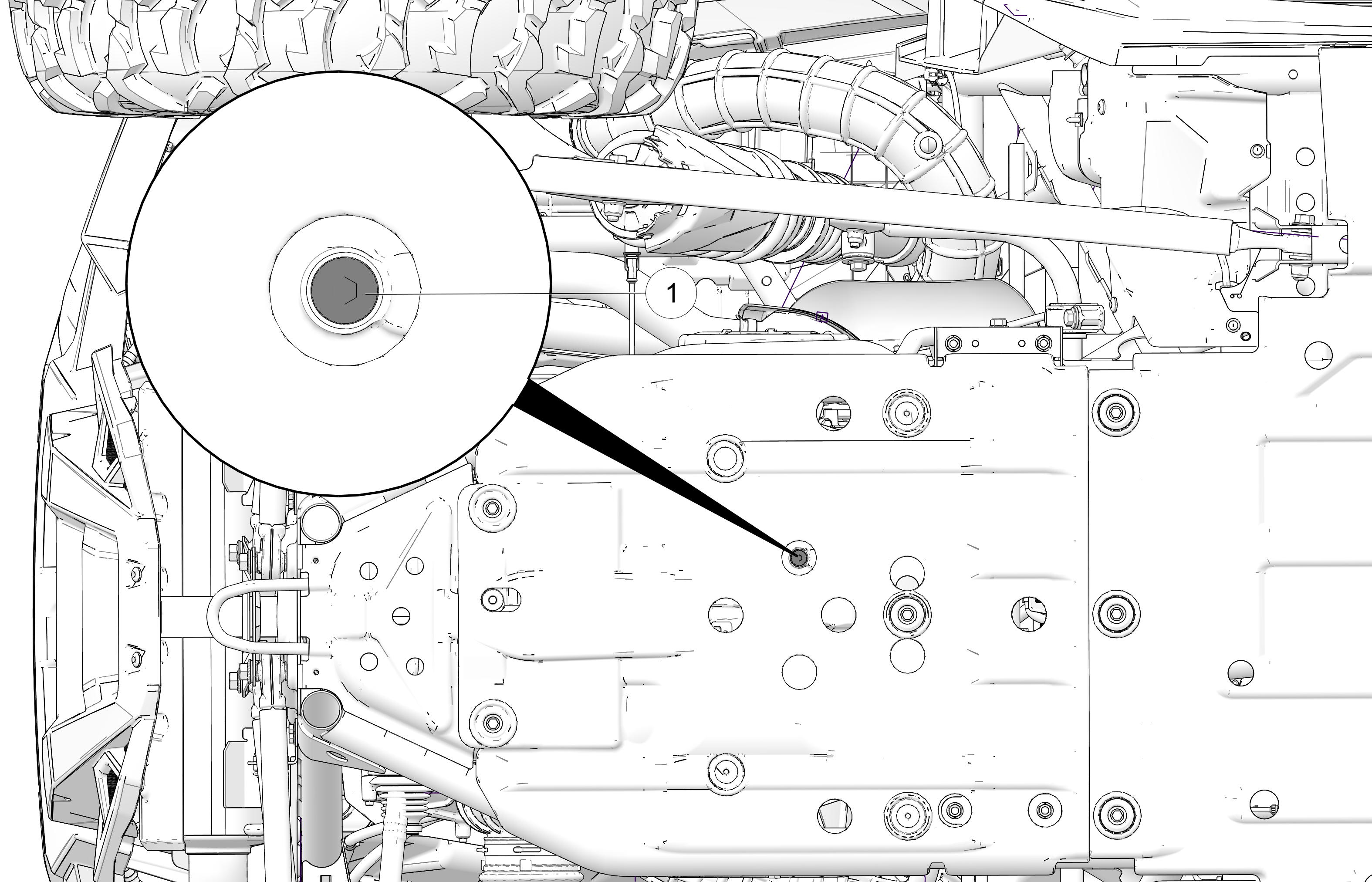
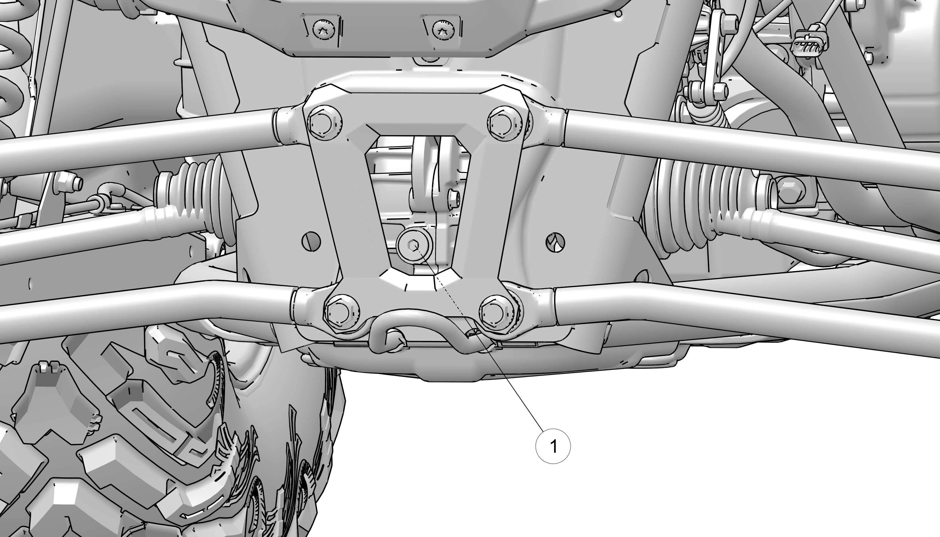
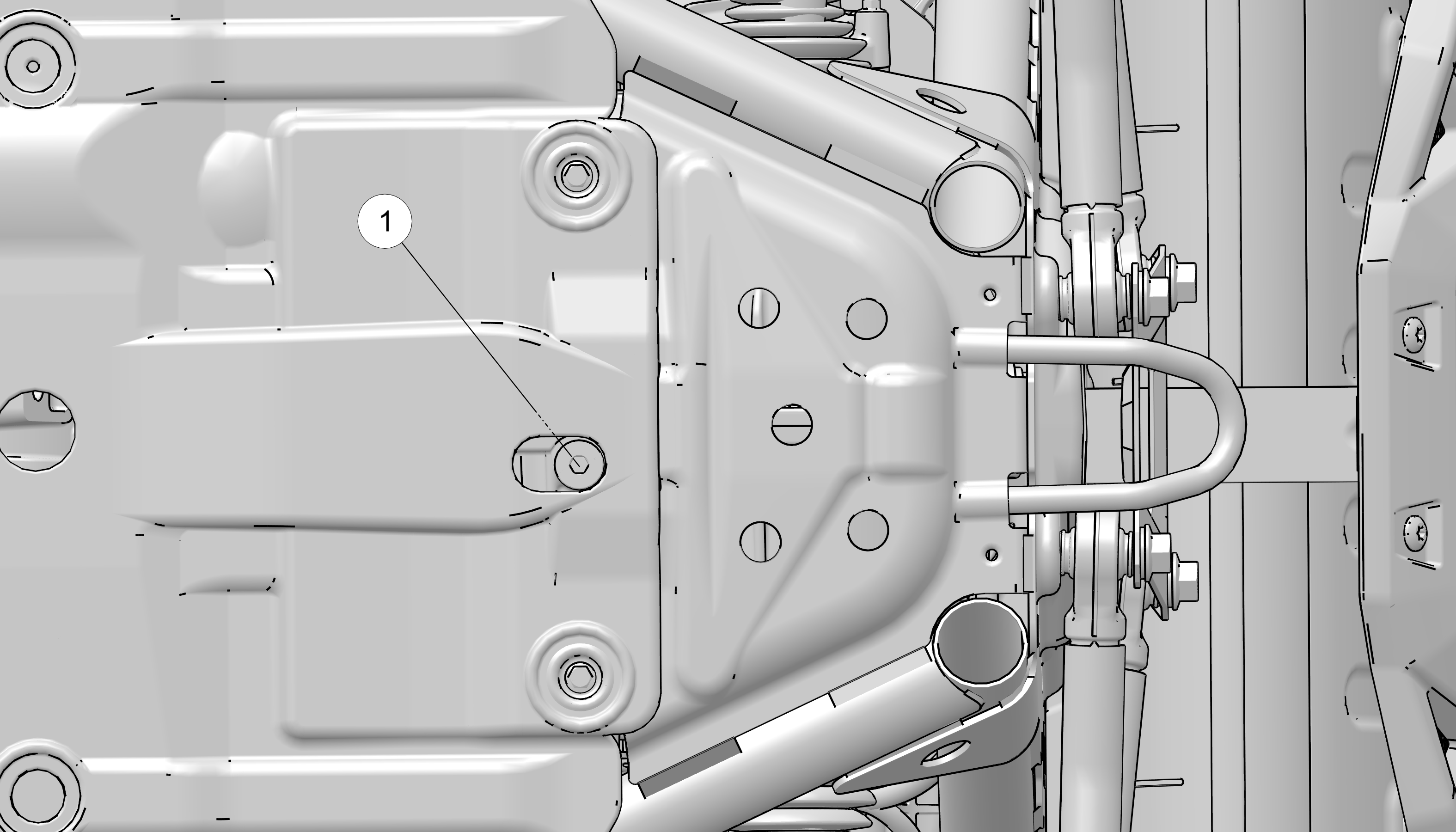
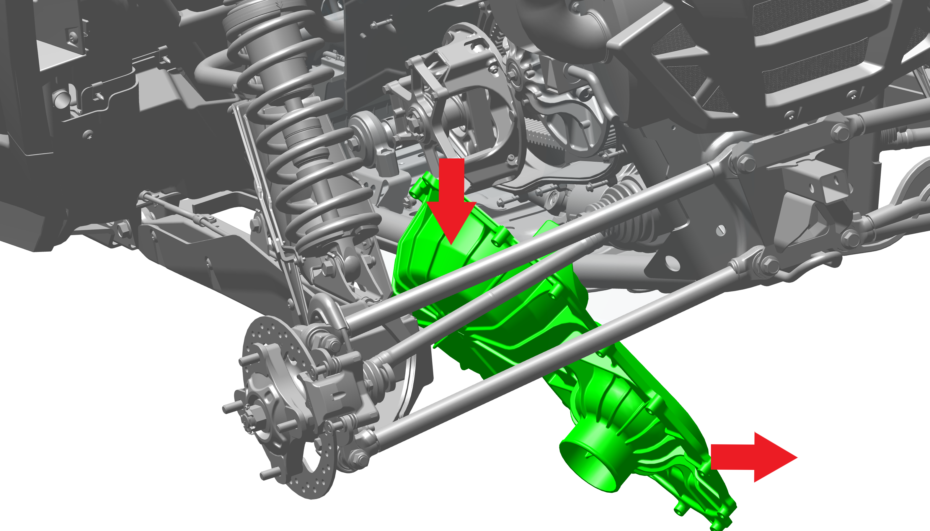
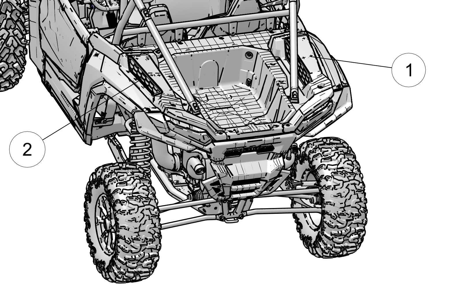
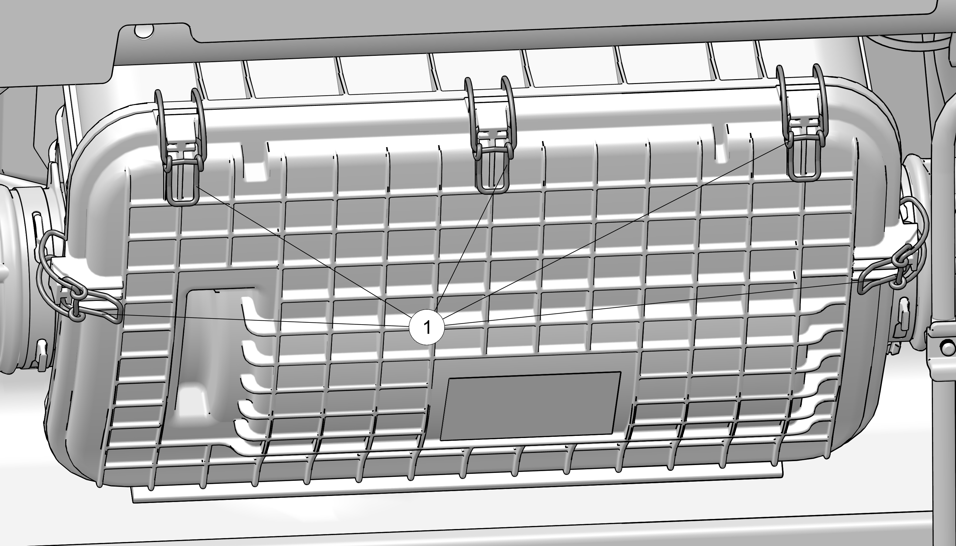
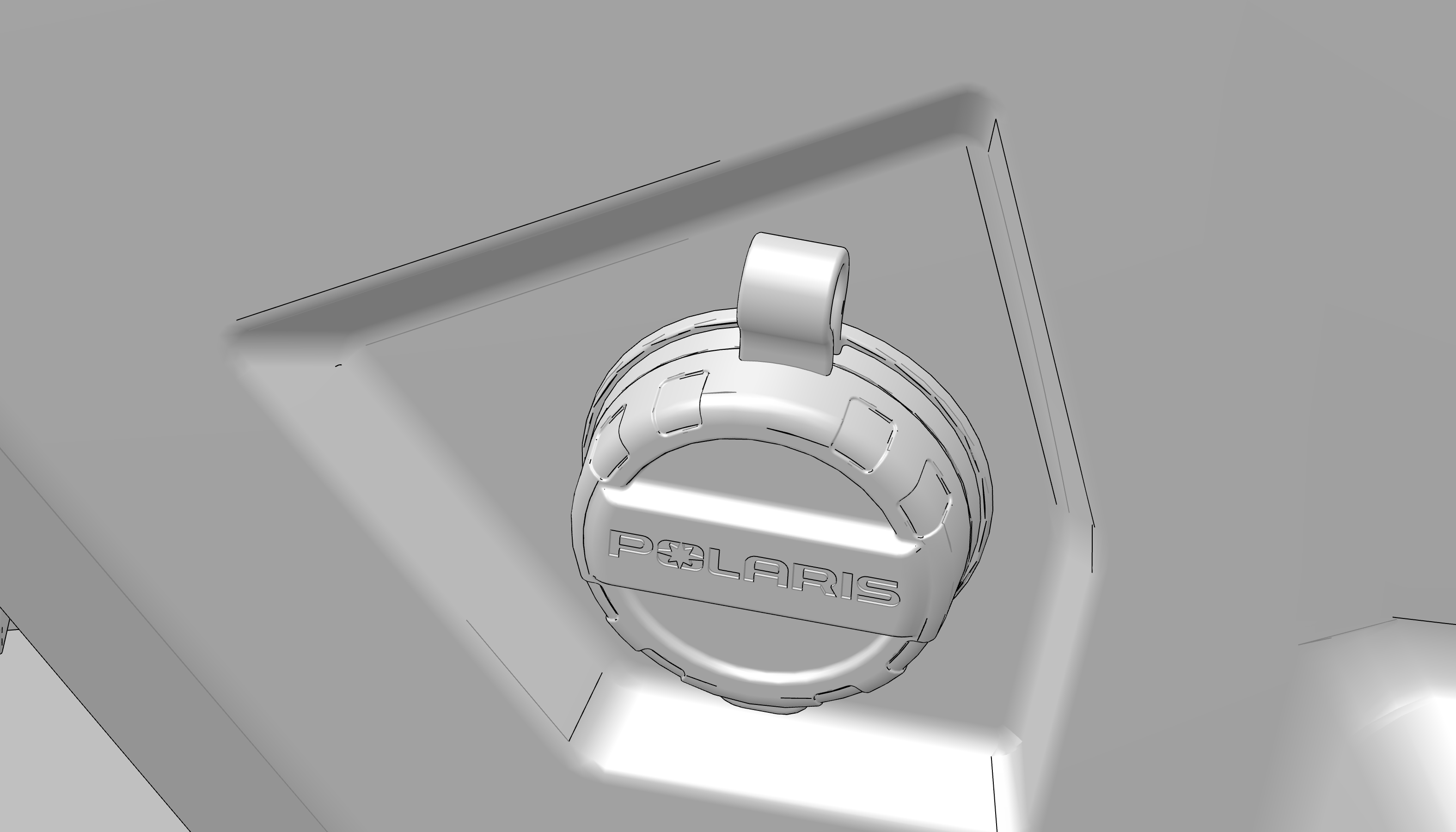
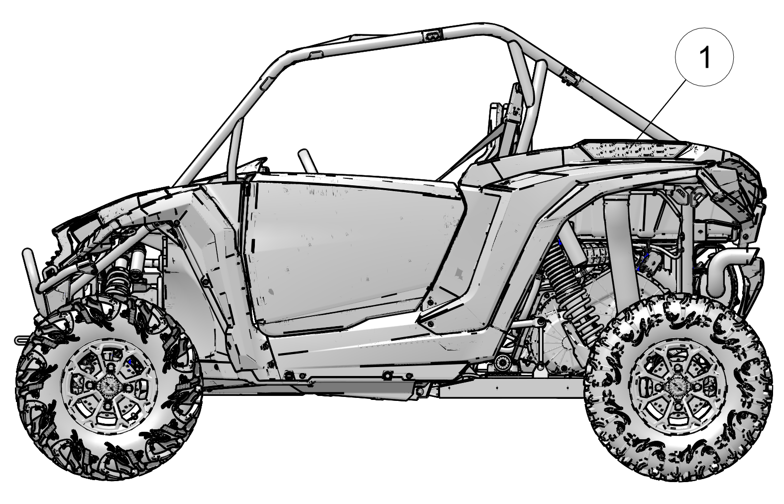
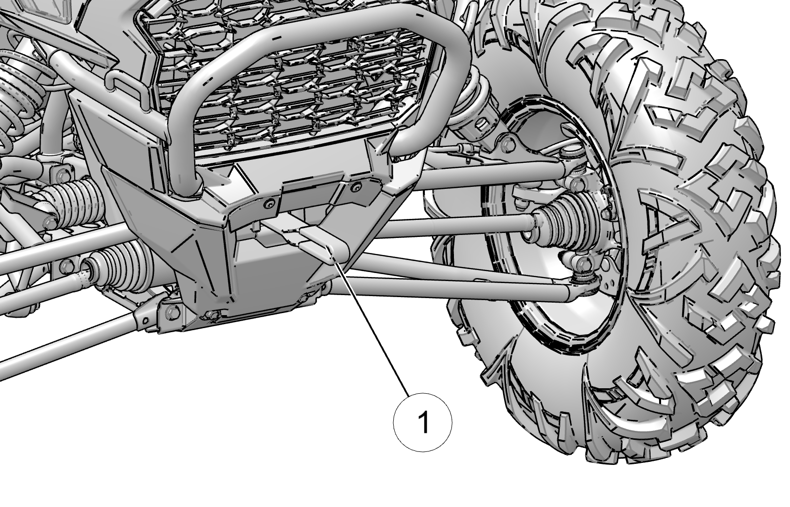
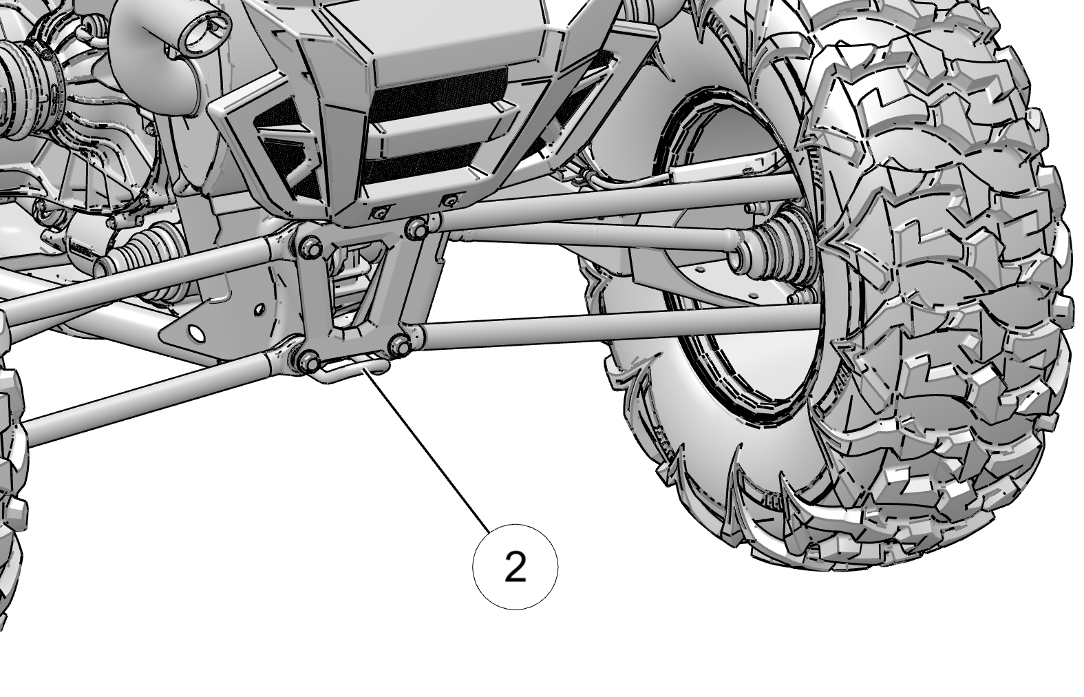
There is a recovery tow loop at the front1 and back2 of the vehicle to attach a winch or strap.
Use these loops to recover this vehicle if it is stuck, to pull
it onto a tow truck, trailer, or to use this vehicle to recover another
vehicle. These loops are for emergency recovery only and are not for
towing vehicles to another location.
Improper recovery may lead to loss of control or vehicle damage.
Only attach straps to specified locations. Do not attach to any other
point on the vehicle. Only recover a vehicle of equal or lesser size
and weight. When recovering a disabled vehicle, place the disabled
vehicle’s transmission in neutral. Do not move a disabled RZR
faster than 10 mph (16 km/h).
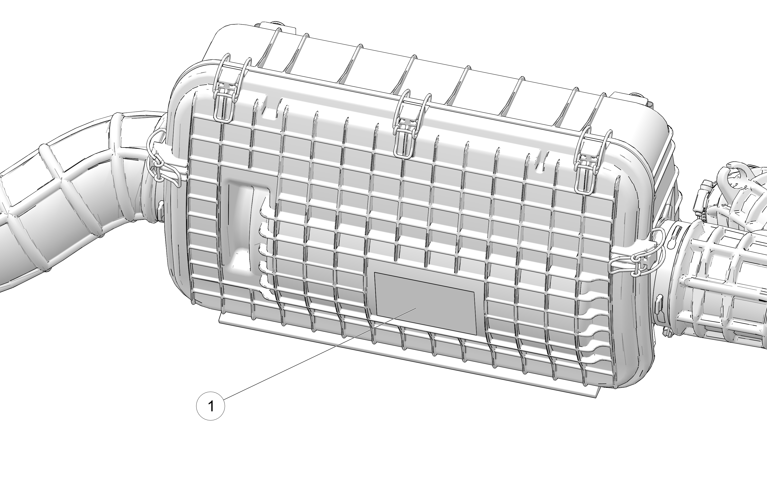
Operating, Idling, Or Parking Near Combustible Materials
Engine, exhaust, and other vehicle components can
be very hot during and after use. Do not idle or park the vehicle
over anything that could contact the exhaust system and catch on fire,
such as tall grass, weeds, brush, leaves, debris, or other tall ground
cover. Do not let mud, grass, or other debris accumulate on the engine
or exhaust system. Inspect and remove as needed.
Vehicle rollaway can cause serious injury or death. This
vehicle can roll whenever the gear selector is not in the PARK (P)
position. Always shift to PARK (P) when stopping the engine or leaving
the vehicle. When leaving the vehicle on an incline is unavoidable,
use extra care. If leaving the vehicle unattended, block the rear
wheels on the downhill side and keep children, pets, and others away
from the gear selector.
Before shifting into reverse, use extra care to make sure the
area is clear of people or obstacles. When it’s safe to
proceed, back slowly.
After operation, inspect the vehicle for damage and debris to make sure the vehicle can be safely stored and operated again.
Some things to inspect include:
-
Debris that could catch fire, such as mud/grass near the engine
or exhaust system
-
Damage to the suspension, steering, or any other part of the
vehicle
-
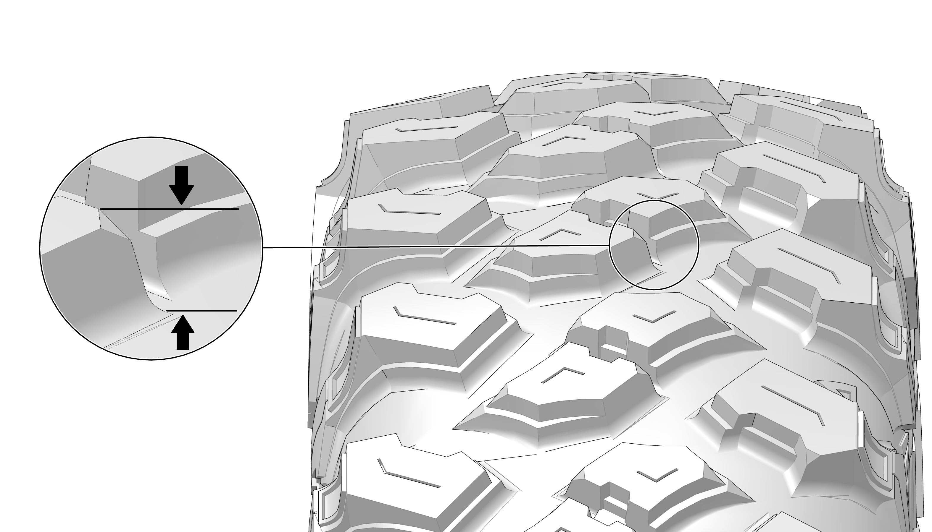
Tire condition, such as tread and sidewall damage
-
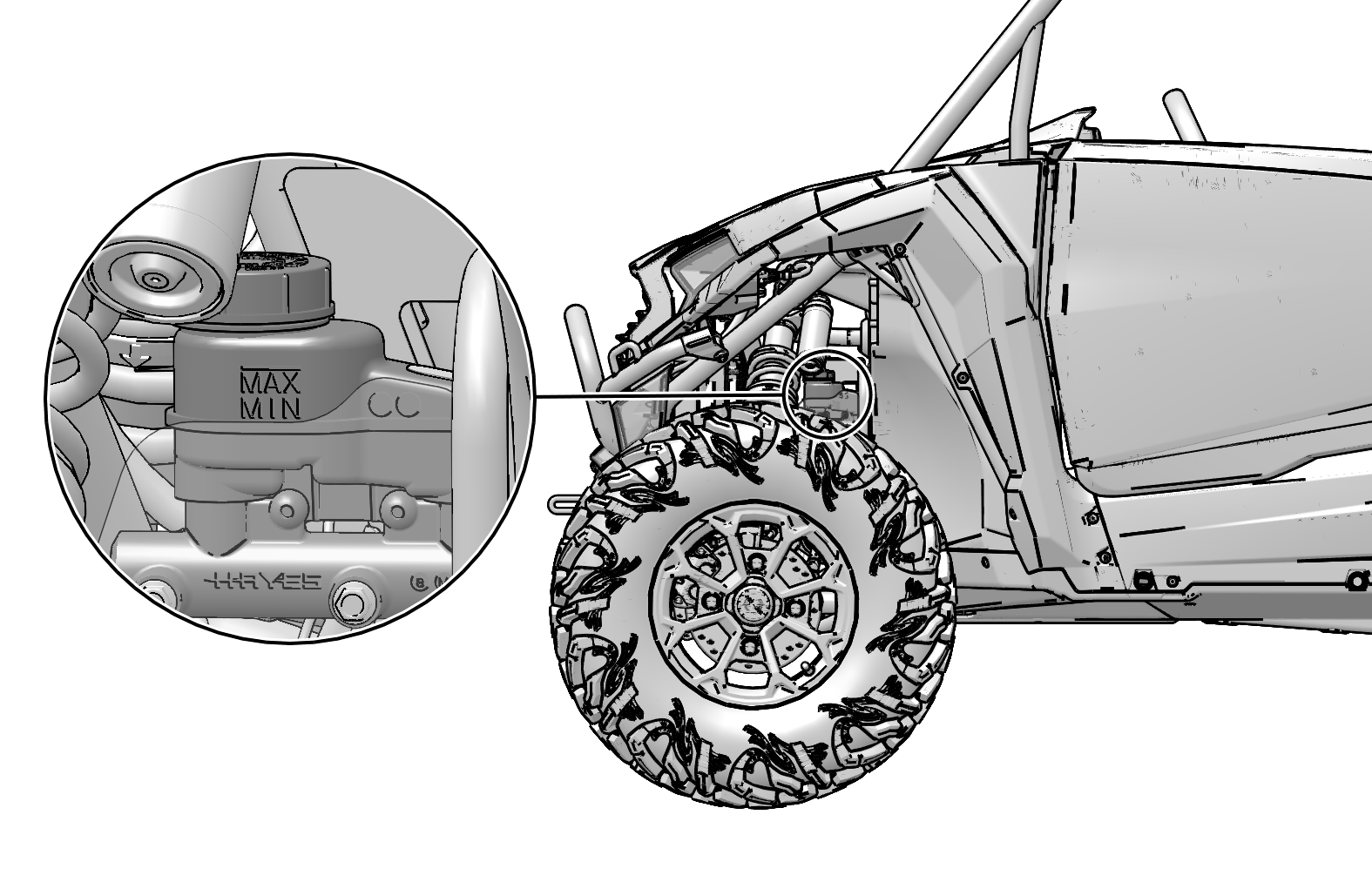
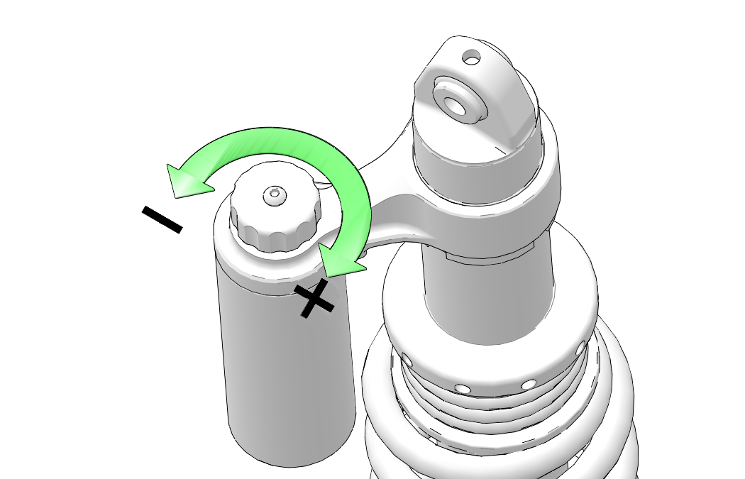
Shock absorber assembly condition
Be sure to have any issues checked and problems fixed before
operating again.
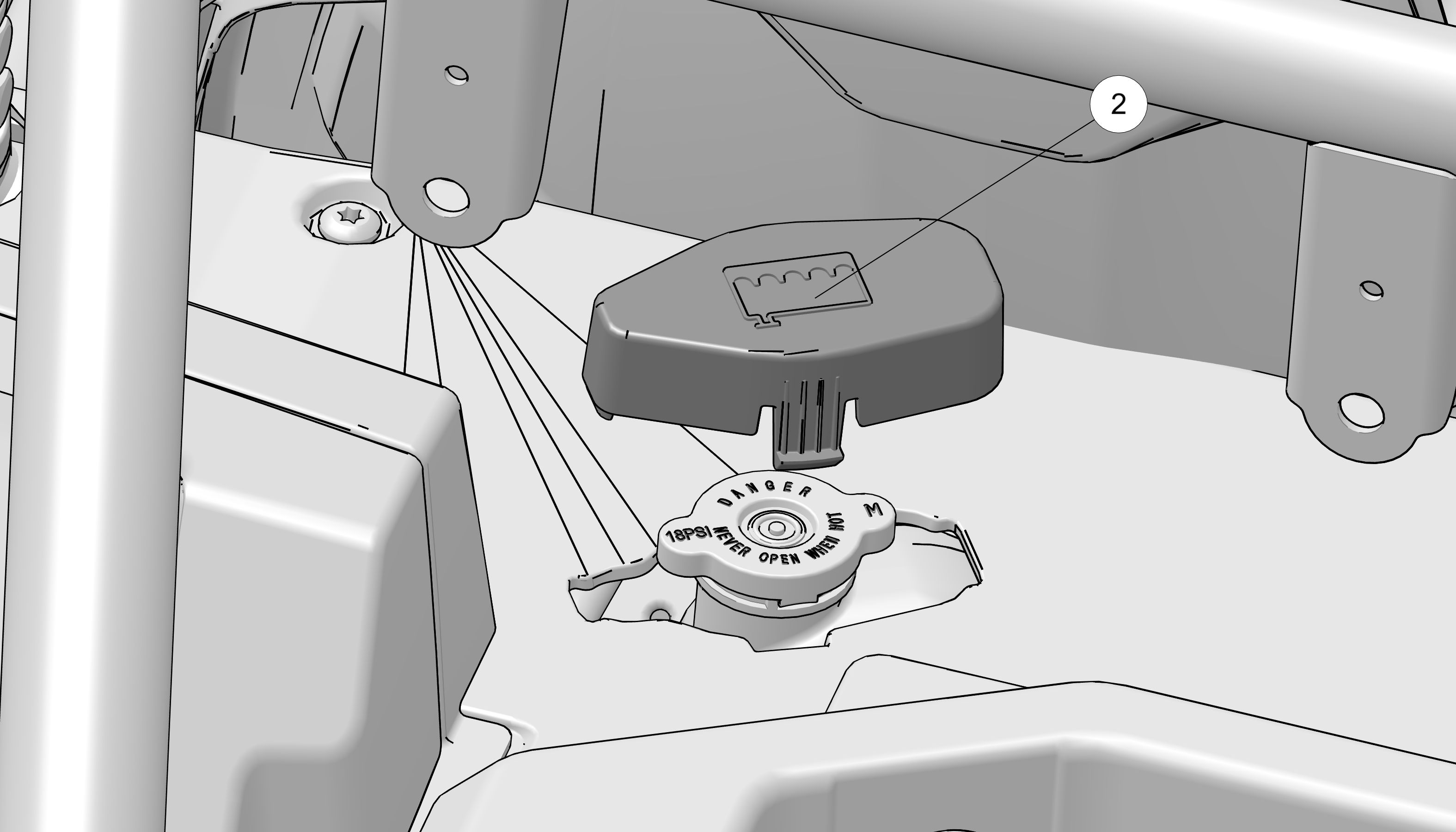
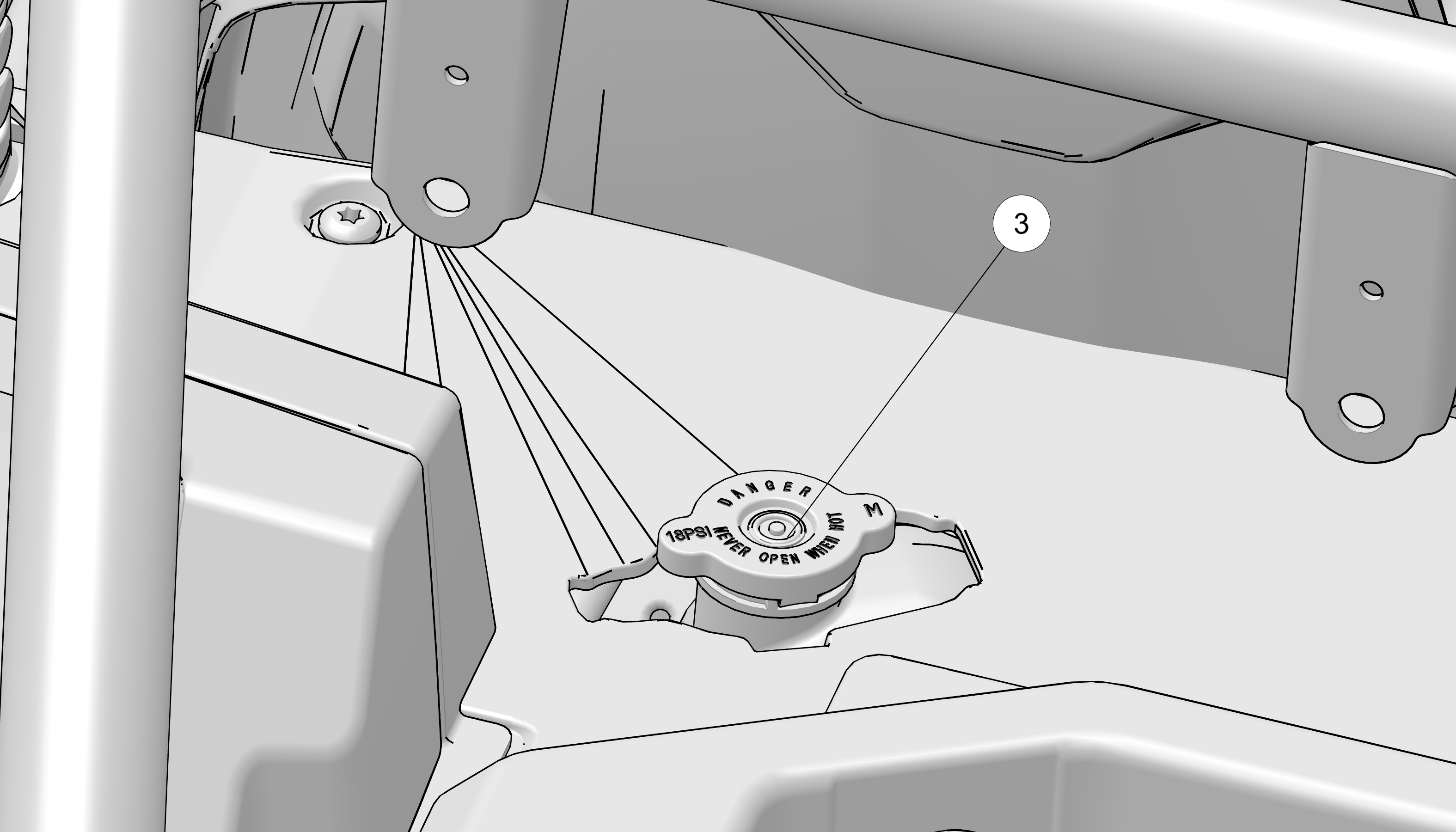
All engine exhaust contains carbon monoxide, a deadly gas.
Breathing carbon monoxide can cause headaches, dizziness, drowsiness,
nausea, confusion, and eventually death. Carbon monoxide is a colorless,
odorless, tasteless gas which may be present even if you do not see
or smell any engine exhaust. Deadly levels of carbon monoxide can
collect rapidly, and you can quickly be overcome and unable to save
yourself. Also, deadly levels of carbon monoxide can linger for hours
or days in enclosed or poorly ventilated areas. If you experience
any symptoms of carbon monoxide poisoning, leave the area immediately,
get fresh air, and SEEK MEDICAL TREATMENT.
-
Do not run engine indoors. Even if you try to ventilate engine
exhaust with fans or open windows and doors, carbon monoxide can rapidly
reach dangerous levels.
-
Do not run engine in poorly ventilated or partially enclosed
areas such as barns, garages, or carports. If you start a vehicle
in one of these, drive it out and close the door as soon as possible.
If you drive it into one of these, turn it off as soon as possible.
-
Do not run engine outdoors where engine exhaust can be drawn
into a building through openings such as windows and doors.
Do not jump-start using jumper cables that are made to connect
one vehicle to another. The battery gives off explosive hydrogen
gas during operation. A spark near the battery can ignite this gas
and cause an explosion. To start a vehicle or charge a battery, use
a portable battery-powered jump starter (such as POLARIS Flex Jump
Starter) or plug-in battery charger, as these products can reduce
the risk of electric shock, fire, and explosion. Improper starting
or charging can damage vehicle electronics.
Be cautious of hot surfaces after the vehicle has been exposed
to direct sunlight for a long period. Risks include discomfort
and burning.