The Owner's Manual for this vehicle contains warnings, instructions and other information you must read and fully understand before safely riding or performing maintenance on this vehicle. Always follow the warnings and instructions in Owner's Manual.
Click the link above for the Table Of Contents, or download a full PDF of the Owner Manual in the Owner Support area of Polaris.com.
2025 Indian Challenger Owner’s
Manual
P/N 9941744
i 2025 Indian Challenger and Pursuit Owner’s Manual
2025 Rider’s
Manual
INDIAN CHALLENGER
INDIAN PURSUIT
INDIAN CHIEFTAIN POWERPLUS
INDIAN ROADMASTER POWERPLUS
Copyright Info
All information contained within this publication is based on the
latest product information available at the time of publication. Product
improvements or other changes may result in differences between this
manual and the motorcycle. Depictions and/or procedures in this publication
are intended for reference use only.
No liability can be accepted for omissions or inaccuracies. Indian
Motorcycle Company reserves the right to make changes at any time,
without notice and without incurring obligation to make the same or
similar changes to motorcycles previously built. Any reprinting or
reuse of the depictions and/or procedures contained within, whether
whole or in part, is expressly prohibited.
Trademarks
Unless noted, trademarks are the property of Indian Motorcycle
International, LLC
RIDE COMMAND® is a registered trademark of POLARIS Industries,
INC. iPhone®, Apple®, App Store®, and Apple CarPlay®
are registered trademarks of Apple Inc. Google Play® is a registered
trademark of Google, LLC. Bluetooth® is a registered trademark
of Bluetooth Sig, Inc. exFAT® is a registered trademark of Microsoft
Corporation. FAT32® is a registered trademark of Microsoft Corporation.
Schrader® is a registered trademark of SENSATA TECHNOLOGIES,
INC. Motorcycle Safety Foundation® is a registered trademark
of Motorcycle Safety Foundation. NGK® is a registered trademark
of NGK Spark Plug Co. Ltd. BatteryMINDer® is a registered trademark
of VDC Electronics. Inc. Marquardt® is a registered trademark
of MARQUARDT GMBH CORPORATION FED REP GERMANY. BOSCH® is registered
to Robert Bosch GmbH. Appareosm℠ is a service trademark of
Appareo Systems, LLC. Metzeler® and Cruisetec® are registered
trademarks of Pirelli Tyre S. P.A. MCASE+® is a registered trademark
of Littelfuse, Inc.
Congratulations on your purchase of a new INDIAN MOTORCYCLE. You
have joined an elite family of motorcycle riders who have acquired
a celebrated piece of American history by choosing to own an INDIAN
MOTORCYCLE.
Your new motorcycle is the end result of true dedication and craftsmanship
by our engineering, design and assembly teams. It was designed and
manufactured to meet our goal of providing you with a high quality
motorcycle that you can ride trouble-free for many years to come.
We hope you will take as much pride in riding your new motorcycle
as our team did in building it for you.
We urge you to read this rider’s manual thoroughly. It contains
information essential to safe riding and proper maintenance of your
motorcycle.
Your authorized INDIAN MOTORCYCLE dealer knows your motorcycle
best and should be consulted for service and assistance. Skilled technicians
using advanced equipment and methods are best qualified to perform
all major repairs and service your motorcycle may require.
INDIAN MOTORCYCLE complies with all federal, state and local safety
and emission regulations for the area of intended sale.
iii Safety Symbols and Signal Words
The following signal words and symbols appear throughout this manual
and on your vehicle. Your safety is involved when these words and
symbols are used. Become familiar with their meanings before reading
the manual.
DANGER
DANGER indicates a hazardous situation which,
if not avoided, WILL result in death or serious injury.
WARNING
WARNING indicates a hazardous situation which,
if not avoided, COULD result in death or serious injury.
CAUTION
CAUTION indicates a hazardous
situation which, if not avoided, COULD result in minor to moderate
injury.
NOTICE
NOTICE provides key information by clarifying
instructions.
IMPORTANT
IMPORTANT provides key reminders during
disassembly, assembly, and inspection of components.
Table Of Contents
Chapter 1: Introduction
1.1.1: Identification Number Records
Record important identification numbers below:
Vehicle Identification
Number (VIN)
Engine Identification Number
Master PIN
Rider PIN
Key Fob #1 Serial Number
Key Fob #2 Serial Number
(optional)
1.1.2: Service and Warranty Information
Some procedures are beyond the scope of this manual. See your dealer
to purchase an INDIAN MOTORCYCLE Service Manual. Some procedures
provided in the service manual require specialized knowledge, equipment,
and training. Be sure you have the required technical skills and tools
that are needed before you attempt ANY service on your motorcycle.
Please contact your authorized dealer before attempting any service
work that is beyond your level of technical knowledge or experience,
or if the work requires specialized equipment.
1.1.2.1: Operating Motorcycle Outside the U.S.A.
If you plan to operate your motorcycle in countries other than
the USA and Canada:
Service facilities or replacement parts may not be readily
available.
Unleaded gasoline may not be available. The use of leaded fuels
will cause engine damage, damage to your emissions systems and voiding
of your warranty.
Gasoline may have a considerably lower octane rating. Improper
fuel can cause engine damage.
1.1.3: Engine Identification Number
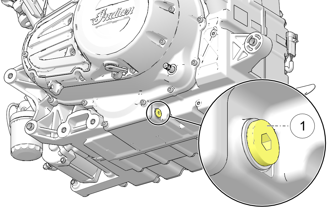
The engine number 1 is stamped into the right crankcase
beneath the balance shaft cover. The engine number is positioned behind
the right floorboard with the engine installed in the frame. Record
the number in the space provided on Identification Number Records.
1.1.4: Device Compliance Statements
NOTICE
Some vehicle models contain radio equipment as
follows:
USA Radio Compliance
This vehicle contains
the following radio equipment or components that contain radio equipment:
COMPONENT
COMPONENT ID
MANUFACTURER
9200 Series Display
RC-7
Polaris Industries Inc.
Tire Pressure Monitoring System (TPMS) Sensor, Model RDC3
(433 MHz)
4019660
Schrader® Electronics
Key Fob, Model SK1 (433 MHz)
4017761/4017768
Marquardt® Switches, Inc.
Wireless Control Module (WCM), Model SE1
4019281
Marquardt® Switches, Inc.
Rear Radar
1914144
Bosch®
Telematic Control Unit (TCU)
4082894
Appareo℠
This device complies with part 15 of the FCC Rules.
Operation is subject to the following two conditions: (1) This device
may not cause harmful interference, and (2) this device must accept
any interference received, including interference that may cause undesired
operation.
CAUTION
Changes or modifications
not expressly approved by the party responsible for compliance could
void the user’s authority to operate the equipment.
This equipment has been tested and found to comply with the
limits for a Class A digital device, pursuant to Part 15 of the FCC
Rules. These limits are designed to provide reasonable protection
against harmful interference when the equipment is operated in a commercial
environment. This equipment generates, uses, and can radiate radio
frequency energy and, if not installed and used in accordance with
the instruction manual, may cause harmful interference to radio communications.
Operation of this equipment in a residential area is likely to cause
harmful interference in which case the user will be required to correct
the interference at his own expense.
Radiofrequency radiation
exposure Information:
This equipment complies with FCC
radiation exposure limits set forth for an uncontrolled environment.
This equipment should be installed and operated with minimum distance
of 20 cm between the radiator and your body.
This transmitter
must not be co-located or operating in conjunction with any other
antenna or transmitter.
Canada Radio Compliance
This vehicle contains
the following radio equipment or components that contain radio equipment:
COMPONENT
COMPONENT ID
MANUFACTURER
9200 Series Display
RC-7
Polaris Industries Inc.
Tire Pressure Monitoring System (TPMS) Sensor, Model RDC3
(433 MHz)
4019660
Schrader® Electronics
Key Fob, Model SK1 (433 MHz)
4017761/4017768
Marquardt® Switches, Inc.
Wireless Control Module (WCM), Model SE1
4019281
Marquardt® Switches, Inc.
Rear Radar
1914144
Bosch®
Telematic Control Unit (TCU)
4082894
Appareo℠
This device complies with Industry Canada license-exempt
RSS standard(s). Operation is subject to the following two conditions:
This device may not cause interference.
This device must accept any interference, including interference
that may cause undesired operation of the device.
Le présent appareil est conforme aux CNR d’Industrie
Canada applicables aux appareils radio exempts de licence. L’exploitation
est autorisée aux deux conditions suivantes:
(1) l’appareil ne doit pas produire de brouillage, et
(2) l’utilisateur de l’appareil doit accepter
tout brouillage radioélectrique subi, même si le brouillage
est susceptible d’en compromettre le fonctionnement.
Radiofrequency radiation exposure Information:
This equipment complies with FCC and IC radiation exposure
limits set forth for an uncontrolled environment. This equipment should
be installed and operated with minimum distance of 20 cm between the
radiator and your body.
This transmitter must not be co-located
or operating in conjunction with any other antenna or transmitter.
Cet équipement est conforme aux limites d’exposition
aux rayonnements IC établies pour un environnement non contrôlé.
Cet équipement doit être installé et utilisé avec
un minimum de 20 cm de distance entre la source de rayonnement et
votre corps. Ce transmetteur ne doit pas etre place au meme endroit
ou utilise simultanement avec un autre transmetteur ou antenne.
European Union (EU) Radio Compliance
This
vehicle contains the following radio equipment or components that
contain radio equipment:
COMPONENT
9200 Series Display
Tire Pressure Monitoring
System (TPMS) Sensor, Model RDC3 (433 MHz)
Key Fob, Model SK1 (433
MHz)
Wireless Control Module
(WCM), Model SE1
Rear Radar
Telematic Control Unit
(TCU)
COMPONENT
ID
RC-7
4019660
4017761/4017768
4019281
1914144
4082895
MANUFACTURER
Polaris Industries Inc.
Schrader® Electronics
Marquardt® Switches,
Inc.
Marquardt® Switches,
Inc.
Bosch®
Appareo℠
TRANSMITTING
FREQUENCY
2402–2480 MHz
433.92 MHz
433.92 MHz
0.02185 MHz
76-77 GHz
LTE, WCDMA, GPRS (703-2690
MHz)
MAX
RF TRANSMITTING PWR
0.2432 W
< 10 mW (e.r.p.)
38.75 dBµV/m @ 3 m
21.2 dBµV/m @ 300 m
24.2 dBµ
LTE, WCDMA: +25 dBµ GPRS: +35 dBµ
Hereby, Polaris Industries Inc. declares that the above
radio equipment is in compliance with Directive 2014/53/EU.
The full text of the EU declaration of conformity is available at
the following internet address:
https://www.polaris.com/en-us/radio-conformity/
Hereby, Robert Bosch GmbH declares that the radio equipment
type MRR1Rear is in compliance with Directive
2014/53/EU.
The full text of the EU declaration of conformity is available
at the following internet address: http://eu-doc.bosch.com
(DE) EU-KONFORMITÄTSERKLÄRUNG
Hiermit
erklärt Robert Bosch GmbH, dass der Funkanlagentyp MRR1Rear der Richtlinie 2014/53/EU entspricht. Der vollständige Text
der EU-Konformitätserklärung ist unter der folgenden Internetadresse
verfügbar: http://eu-doc.bosch.com
(BG) ЕС
ДЕКЛАРАЦИЯ
ЗА СЪОТВЕТСТВИЕ
С настоящото
Robert Bosch GmbH декларира,
че този тип
радиосъоръжение MRR1Rear е в съответствие
с Директива
2014/53/ЕС. Цялостният
текст на ЕС
декларацията
за съответствие
може да се намери
на следния интернет
адрес: http://eu-doc.bosch.com
(HR) EU IZJAVA O SUKLADNOSTI
Robert Bosch GmbH ovime
izjavljuje da je radijska oprema tipa MRR1Rear u skladu s Direktivom
2014/53/EU. Cjeloviti tekst EU izjave o sukladnosti dostupan je na
sljedećoj internetskoj adresi: http://eu-doc.bosch.com
(EL) ΔΗΛΩΣΗ ΣΥΜΜΟΡΦΩΣΗΣ
ΕΕ
Με την παρούσα
ο/η Robert Bosch GmbH, δηλώνει
ότι ο ραδιοεξοπλισμός MRR1Rear πληροί την
οδηγία 2014/53/ΕΕ.
Το πλήρες κείμενο
της δήλωσης
συμμόρφωσης
ΕΕ διατίθεται
στην ακόλουθη
ιστοσελίδα
στο διαδίκτυο:
http://eu-doc.bosch.com
(CS) EU PROHLÁŠENÍ
O SHODĚ
Tímto Robert Bosch GmbH prohlašuje,
že typ rádiového zařízení MRR1Rear je v souladu se směrnicí 2014/53/EU. Úplné znění
EU prohlášení o shodě je k dispozici na této
internetové adrese: http://eu-doc.bosch.com
(DA) EU-OVERENSSTEMMELSESERKLÆRING
Hermed erklærer Robert Bosch GmbH, at radioudstyrstypen MRR1Rear er i overensstemmelse med direktiv 2014/53/EU. EU-overensstemmelseserklæringens
fulde tekst kan findes på følgende internetadresse: http://eu-doc.bosch.com
(ET) ELI VASTAVUSDEKLARATSIOON
Käesolevaga
deklareerib Robert Bosch GmbH, et käesolev raadioseadme tüüp MRR1Rear vastab direktiivi 2014/53/EL nõuetele. ELi vastavusdeklaratsiooni
täielik tekst on kättesaadav järgmisel internetiaadressil:
http://eu-doc.bosch.com
(FI) EU- VAATIMUSTENMUKAISUUSVAKUUTUS
Robert Bosch GmbH vakuuttaa, että radiolaitetyyppi MRR1Rear on direktiivin 2014/53/EU mukainen. EU-vaatimustenmukaisuusvakuutuksen
täysimittainen teksti on saatavilla seuraavassa internetosoitteessa:
http://eu-doc.bosch.com
(FR) DECLARATION UE DE CONFORMITE
Le soussigné, Robert Bosch GmbH, déclare que l’équipement
radioélectrique du type MRR1Rear est conforme à la
directive 2014/53/UE. Le texte complet de la déclaration UE de
conformité est disponible à l’adresse internet suivante:
http://eu-doc.bosch.com
(HU) EU-MEGFELELŐSÉGI
NYILATKOZAT
Robert Bosch GmbH igazolja, hogy a MRR1Rear típusú rádióberendezés megfelel a 2014/53/EU
irányelvnek. Az EU-megfelelőségi nyilatkozat teljes
szövege elérhető a következő internetes
címen: http://eu-doc.bosch.com
(IT) DICHIARAZIONE DI
CONFORMITÀ UE
Il fabbricante, Robert Bosch GmbH, dichiara
che il tipo di apparecchiatura radio MRR1Rear è conforme
alla direttiva 2014/53/UE. Il testo completo della dichiarazione di
conformità UE è disponibile al seguente indirizzo Internet:
http://eu-doc.bosch.com
(LV) ES ATBILSTĪBAS DEKLARĀCIJA
Ar šo Robert Bosch GmbH deklarē, ka radioiekārta MRR1Rear atbilst Direktīvai 2014/53/ES. Pilns ES atbilstības
deklarācijas teksts ir pieejams šādā interneta
vietnē: http://eu-doc.bosch.com
(LT) ES ATITIKTIES
DEKLARACIJA
Aš, Robert Bosch GmbH, patvirtinu, kad
radijo įrenginių tipas MRR1Rear atitinka Direktyvą
2014/53/ES. Visas ES atitikties deklaracijos tekstas prieinamas šiuo
interneto adresu: http://eu-doc.bosch.com
(MT) DIKJARAZZJONI
TA’ KONFORMITÀ TAL-UE
B’dan, Robert
Bosch GmbH, niddikjara li dan it-tip ta’ tagħmir tar-radju MRR1Rear huwa konformi mad-Direttiva 2014/53/UE. It-test kollu
tad-dikjarazzjoni ta’ konformità tal-UE huwa disponibbli
f’dan l-indirizz tal-Internet li ġej: http://eu-doc.bosch.com
(NL) EU-CONFORMITEITSVERKLARING
Hierbij verklaar
ik, Robert Bosch GmbH, dat het type radioapparatuur MRR1Rear conform is met Richtlijn 2014/53/EU. De volledige tekst van de EU-conformiteitsverklaring
kan worden geraadpleegd op het volgende internetadres: http://eu-doc.bosch.com
(PL) DEKLARACJA ZGODNOŚCI UE
Robert Bosch
GmbH niniejszym oświadcza, że typ urządzenia radiowego MRR1Rear jest zgodny z dyrektywą 2014/53/UE. Pełny
tekst deklaracji zgodności UE jest dostępny pod następującym
adresem internetowym: http://eu-doc.bosch.com
(PT) DECLARAÇÃO
UE DE CONFORMIDADE
O(a) abaixo assinado(a) Robert Bosch
GmbH declara que o presente tipo de equipamento de rádio MRR1Rear está em conformidade com a Diretiva 2014/53/UE. O texto integral
da declaração de conformidade está disponível
no seguinte endereço de Internet: http://eu-doc.bosch.com
Japan Radio Compliance
This vehicle contains
the following radio equipment or components that contain radio equipment:
COMPONENT
COMPONENT ID
MANUFACTURER
9200 Series Display
RC-7
Polaris Industries Inc.
Key Fob, Model SK1 (315 MHz)
4019468/4019469
Marquardt® Switches, Inc.
Wireless Control Module (WCM), Model SE1
4019281
Marquardt® Switches, Inc.
Rear Radar
1914144
Bosch®
Telematic Control Unit (TCU)
4082895
Appareo℠
当該機器には電波法に基づく、技術基準適合証明等を受けた特定無線設備を装着している。
Translation: This equipment contains specified radio equipment
that has been certified to the technical regulation conformity certification
under the Radio Law.
本無線機器の改造を禁ずる(これに反した場合は当該認証登録番号は無効となる)
Translation: This radio device should not be modified (otherwise
the granted designation number will become invalid)
Mexico Radio Compliance
This vehicle contains
the following radio equipment or components that contain radio equipment:
COMPONENT
COMPONENT ID
MANUFACTURER
IFETEL CERTIFICATE
9200 Series Display
RC-7
Polaris Industries Inc.
RCPPORC20–1082
Tire Pressure Monitoring System (TPMS) Sensor, Model RDC3
(433 MHz)
4019660
Schrader® Electronics
RLVSCRD16-0534
Key Fob, Model SK1 (433 MHz)
4017761/4017768
Marquardt® Switches, Inc.
RLVPOSK19–1418
Wireless Control Module (WCM), Model SE1
4019281
Marquardt® Switches, Inc.
RLVPOSE19–1419
Rear Radar
1914144
Bosch®
RCPBOMR14-0922
Telematic Control Unit (TCU)
4082895
Appareo℠
POPOTC24-07625
IFETEL:
La operación de este equipo está
sujeta a las siguientes dos condiciones:
Es posible que este equipo o dispositivo no cause interferencia
perjudicial.
Este equipo o dispositivo debe aceptar cualquier interferencia,
incluyendo la que pueda causar su operación no deseada.
справжнім
(Robert Bosch GmbH) заявляє,
що тип радіообладнання
(MRR1Rear) відповідає
Технічному
регламенту
радіообладнання;
повний текст
декларації
про відповідність
доступний на
веб-сайті за
такою адресою:
(http://ita.bosch.com/radar)
Hereby, Robert Bosch GmbH
declares that the radio equipment type MRR1Rear is in compliance with
Radio Equipment Regulations 2017. The full text of the UK declaration
of conformity is available at the following internet address:
https://ita.bosch.com
This telecommunication equipment "BOSCH
Radar Sensor MRR1Rear " conforms to technical standard NTC TS 1011-2549.
This telecommunication equipment "BOSCH Radar Sensor MRR1Rear
" has EMF radiation and conforms to NTC exposure standard NTC TS 5001-2550.
This equipment "BOSCH Radar Sensor MRR1Rear " is operating more
than 20cm away from human body in normal operating condition.
If you believe that your vehicle has a defect that could result
in a crash or cause injury or death, you should immediately inform
the National Highway Traffic Safety Administration (NHTSA) in addition
to notifying INDIAN MOTORCYCLE in writing.
If NHTSA receives similar complaints, it may open an investigation,
and if it finds that a safety defect exists in a group of vehicles,
it may order a recall and remedy campaign. However, NHTSA cannot become
involved in individual problems between you, your INDIAN MOTORCYCLE
dealer or INDIAN MOTORCYCLE.
To contact NHTSA, or obtain other information about motor vehicle
safety, you may either call the Vehicle Safety Hotline toll-free at
1-888-327-4236 (TTY: 1-800-424-9153), visit the NHTSA website at www.safercar.gov,
or write to:
ADMINISTRATOR, NHTSA 1200 New Jersey Avenue,
SE West Building Washington, DC 20590
1.1.6: Reporting Safety Defects (Canada)
To report a safety defect to Transport Canada, you may either fill
out an online defect complaint form at their website (English: http://www.tc.gc.ca/recalls, French: http://www.tc.gc.ca/rappels) or contact their Defect Investigations and Recalls Division by
calling toll-free 1-800-333-0510 (Canada) or 819-994-3328 (Ottawa-Gatineau
area / International).
1.1.7: Electromagnetic Interference
This vehicle complies with UN ECE Regulation 10 requirements and
Canadian ICES-002.
Chapter 2: Safety
2.2.1: About the Rider’s Manual
WARNING
Failure to follow all recommended precautions
and procedures could result in serious injury or death. Always heed
all safety precautions and follow all operation, inspection and maintenance
procedures outlined in this manual.
All references to RIGHT, LEFT, FRONT or REAR are from the operator’s
perspective when seated in a normal riding position. If you have questions
about the operation or maintenance of your motorcycle after you’ve
read this manual, please see your authorized dealer. To locate the
nearest authorized INDIAN MOTORCYCLE dealer, visit the INDIAN MOTORCYCLE
website at https://www.indianmotorcycle.com/en-us/.
Carefully read and understand the information found in the Safety section beginning on this page. To keep your motorcycle in peak
condition on the road or in storage, understand and follow the procedures
outlined in the Maintenance section beginning on Safety During Service Procedures.
Bring the manual along when you ride. Following the precautions
and procedures in the manual will add to your enjoyment and help keep
you safe. If you lose or damage this manual, please purchase a new
one through any authorized INDIAN MOTORCYCLE dealer. This rider’s
manual should be considered part of the motorcycle and should remain
with the motorcycle when ownership changes.
For the most up-to-date owner’s manual visit https://www.indianmotorcycle.com/en-us/owners-manuals.
2.2.2: Safe Riding Practices
WARNING
Improper use of a motorcycle can result in serious
injury or death to you, your passenger and others. To minimize the
risk of injury, read and understand the information contained in this
section before operating the motorcycle. This section contains safety
information specific to the INDIAN MOTORCYCLE, as well as information
about general motorcycle safety. Anyone who rides the motorcycle (operators
and passengers) must follow these safety precautions.
2.2.2.1: Motorcycling Has Inherent Risks
You can minimize those risks, but you can’t eliminate them
completely. Even if you’re an experienced motorcycle operator
or passenger, read all of the safety information in this manual before
operating the motorcycle.
Take a rider education course from the Motorcycle Safety Foundation®
or another qualified instructor. The course will help you develop
or refresh your expertise in safe riding habits through instruction
and riding. For information on Motorcycle Safety Foundation®
rider education courses in your area, call 1-800-446-9227 or visit https://msf-usa.org/.
Read, understand, and follow all information in this manual.
Observe all maintenance requirements specified in this manual.
See the INDIAN MOTORCYCLE Service Manual or an authorized INDIAN MOTORCYCLE
dealer.
2.2.2.2: Design Characteristics Affect Riding
The motorcycle is designed for on-road use with one rider (and
one passenger if the motorcycle is equipped with a passenger seat). Never exceed the GVWR or the GAWR. Refer to the Specifications section, or the Manufacturing Information/VIN label on the motorcycle
frame for model-specific information.
Riding off-road, riding with more than one passenger, or carrying
weight exceeding the maximum weight rating can make handling difficult,
which could cause loss of control.
During the first 500 miles (800 km) of operation, follow all
break-in procedures as outlined on Engine Break-In. Failure to do so can result in serious
engine damage.
If your motorcycle is equipped with saddlebags, a windshield
or a passenger backrest, be prepared to reduce operating speed to
maintain stability.
2.2.2.3: Follow These General Safe Riding Practices
Before each ride, perform the Pre-Ride Inspections. Failure
to do so may result in damage to the motorcycle or an accident.
Until you’re thoroughly familiar with the motorcycle
and all of its controls, practice riding where there is little or
no traffic. Practice riding at a moderate speed on various road surfaces
and in different weather conditions.
Know your skills and limits, and ride within them.
Allow only licensed, experienced operators to ride your motorcycle,
and then only after they have become familiar with its controls and
operation. Make sure all riders read and understand this rider’s
manual before riding.
Do not ride when you’re fatigued, ill or under the influence
of alcohol, prescription drugs, over-the-counter drugs or any other
drugs. Fatigue, illness, alcohol and drugs can cause drowsiness, loss
of coordination and loss of balance. They can also affect your awareness
and judgment.
If your motorcycle operates abnormally, correct the problem
immediately. See the INDIAN MOTORCYCLE Service Manual or an
authorized INDIAN MOTORCYCLE dealer.
Ride defensively, as if you are invisible to other motorists,
even in broad daylight. A motorist’s failure to see or recognize
a motorcycle is the leading cause of automobile/motorcycle accidents. Ride where you’re clearly visible to other motorists, and
observe their behavior carefully.
Be especially cautious at intersections, as these are the most
likely places for an accident.
To prevent loss of control, keep your hands on the handlebars
and your feet on the footrests.
Be aware that a highway bar is not designed to protect the
rider from injury in a collision.
Obey the speed limit and adjust your speed and riding technique
based on road, weather and traffic conditions. As you travel faster,
the influence of all other conditions increases, which can affect
the motorcycle’s stability and increase the possibility of
losing control.
Do not move or operate the motorcycle with the steering locked
(if equipped), as the severely restricted steering could result in
loss of control.
Reduce speed when:
The road has potholes or is otherwise rough or uneven.
The road contains sand, dirt, gravel or other loose substances.
The road is wet, icy or oily.
The road contains painted surfaces, manhole covers, metal grating,
railway crossings or other slippery surfaces.
The weather is windy, rainy or otherwise causing slippery or
rapidly changing conditions.
Traffic is heavy, congested, not allowing sufficient space
between vehicles or otherwise not flowing smoothly.
You are being passed in either direction by a large vehicle
that may produce a wind blast in its wake.
When approaching a curve, choose a speed and lean angle that
allows you to pass through the curve in your own lane without applying
the brakes. Excessive speed, improper lean angle or braking in a curve
can cause loss of control.
Ground clearance is reduced when the motorcycle leans. Do not
allow components to contact the road surface when leaning the motorcycle
in a curve, as this could cause loss of control.
Do not tow a trailer. Towing a trailer can make the motorcycle
hard to handle.
Retract the sidestand fully before riding. If the sidestand
is not fully retracted, it could contact the road surface and cause
loss of control.
To maximize braking effectiveness, use the front and rear
brakes together. Be aware of the following braking facts and practices:
The rear brake provides 40% of the motorcycle’s stopping
power, at most. Use the front and rear brakes together.
To avoid skidding, apply the brakes gradually when the road
is wet or rough, or contains loose or other slippery substances.
If possible, avoid applying the brakes while making a turn.
Motorcycle tires have less traction during turns, so braking will
increase the possibility of skidding. Bring the motorcycle to the
upright position before applying the brakes.
With new pads and rotors, brake performance will be less effective.
Avoid using brakes harshly, unless in an emergency, to allow pads
to mate with rotors. Brake efficiency will gradually increase during
this seating period.
Hot engine and exhaust components can cause burns to skin and
can ignite a fire if exposed to flammable materials. Always park the
motorcycle clear of flammable materials and where people are not likely
to contact hot components.
2.2.3: Protective Apparel
IMPORTANT
Wear protective apparel to decrease the risk
of injury and increase riding comfort.
Always wear a helmet that meets or exceeds established safety
standards. Approved helmets in the USA and Canada bear a U.S. Department
of Transportation (DOT) label. Approved helmets in Europe, Asia and
Oceania bear the ECE 22.05 label. The ECE mark consists of a circle
surrounding the letter E, followed by the distinguishing number of
the country which has granted approval. The approval number and serial
number will also be displayed on the label. Laws in some areas require that you wear an approved helmet. Head injuries are the
leading cause of fatalities in accidents involving motorcycles. Statistics
prove that an approved helmet is the most effective protection in
preventing or reducing head injuries. The helmet should fit snugly,
be securely fastened, have no obvious defects, and have not previously
been involved in an accident/crash.
Wear eye protection to protect eyes from wind or airborne particles
and objects. Wearing a face shield can help protect your face in an
accident/crash and protect face from wind or airborne particles or
objects. Laws in some areas require that you wear eye protection.
We recommend that you wear approved Personal Protective Equipment
(PPE) bearing markings such as VESC 8, V-8, Z87.1, or CE. Make sure
protective eyewear is kept clean.
All riders should wear bright or light-colored and/or reflective
clothing to improve visibility to other motorists. A motorist’s
failure to see or recognize a motorcycle is the leading cause of automobile/motorcycle
accidents.
Wear gloves, a jacket, heavy boots and long pants to prevent
or reduce injury from abrasions, lacerations or burns should the motorcycle
fall. Wear boots with low heels, as high heels can catch on pedals
or footrests. The combination of boots and pants should completely
cover legs, ankles and feet, protecting skin from engine and exhaust
system heat.
Do not wear loose, flowing clothing or long boot laces, as
they can catch on handlebars, levers or footrests, or they can become
entangled in the wheels, causing loss of control and serious injury.
Long-term exposure to wind and engine noise can cause permanent
hearing loss. Properly worn hearing protective devices such as earplugs
can help prevent hearing loss. Check local laws or the rules of the
riding area you are in before wearing hearing protection to make sure
its use is permitted.
2.2.4: Carrying a Passenger
WARNING
Do not carry a passenger unless the motorcycle
is equipped with passenger seat and passenger footrests.
2.2.5: Carrying Cargo
Use the following guidelines when attaching cargo or accessories
to the motorcycle. Where applicable, these guidelines also refer to
the contents of any accessories.
Keep cargo and accessory weight to a minimum, and keep items as
close to the motorcycle as possible to minimize a change in the motorcycle’s
center of gravity. Changing the center of gravity can cause loss of
stability and handling and could cause loss of control.
Do not exceed the GROSS VEHICLE WEIGHT RATING (GVWR) or the
GROSS AXLE WEIGHT RATING (GAWR) for your motorcycle.
Distribute weight evenly on both sides of the motorcycle. Maintain
even weight distribution by checking accessories and cargo to make
sure they’re securely attached to the motorcycle before riding
and whenever you take a break from riding. Uneven weight distribution
or sudden shifting of accessories or cargo while you’re riding
may cause difficult handling, loss of control and driving hazards
for other motorists (if cargo falls from the motorcycle).
For riding comfort and to ensure proper ground clearance, adjust
rear shock air pressure (if equipped) as specified on the label located
under the left side cover. See Shock Preload Adjustment.
Do not attach large or heavy cargo such as sleeping bags, duffel
bags or tents to the handlebars, front fork area or front fender.
Cargo or accessories placed in these areas can cause instability (due
to improper weight distribution or aerodynamic changes) and could
cause loss of control. Such items can also block air flow to the engine
and cause overheating that can damage the engine.
Do not exceed the maximum cargo weight limit of any accessory
(see accessory instructions and labels). Do not attach cargo to an
accessory not designed for that purpose. Either circumstance could
result in an accessory failure that could cause loss of control.
Always obey posted speed limits.
Do not attach anything to the motorcycle unless specifically
designed for that purpose by INDIAN MOTORCYCLE.
2.2.6: Saddlebags and Other Storage
Whenever operating a motorcycle equipped with cargo storage features
such as saddlebags, racks, glove boxes or other storage compartments:
Never ride at excessive speeds. Storage features and cargo, combined
with the lifting or buffeting effects of wind, can make a motorcycle
unstable and cause loss of control.
Distribute weight evenly on each side of the motorcycle.
Do not exceed the individual weight limit of any saddlebag
or other storage compartment. Refer to the storage capacity label
located on or near the storage feature.
NEVER EXCEED the GROSS VEHICLE WEIGHT RATING (GVWR) or the
GROSS AXLE WEIGHT RATING (GAWR), regardless of whether or not any
storage feature is loaded to capacity. Exceeding the weight rating
can reduce stability and handling and cause loss of control.
Because INDIAN MOTORCYCLE cannot test and make specific recommendations
concerning every accessory or combination of accessories sold, the
operator is responsible for determining that the motorcycle can be
safely operated with any accessories or additional weight. Use the
following guidelines when choosing and installing accessories:
Do not install accessories that impair operator visibility
or the stability, handling or operation of the motorcycle. Before
installing an accessory, be sure that it does not:
reduce ground clearance when the motorcycle is either leaned
or in a vertical position;
limit suspension or steering travel or your ability to operate
controls;
displace you from your normal riding position;
obscure lights or reflectors.
Bulky, heavy or large accessories can cause instability (due
to the lifting or buffeting effects of wind) and loss of control.
Do not install electrical accessories that exceed the capacity
of the motorcycle’s electrical system. Never install higher
wattage light bulbs than those supplied as original equipment. An
electrical failure could result and cause hazardous loss of engine
power or lights, or damage to the electrical system.
Use only genuine INDIAN MOTORCYCLE accessories designed for
your model.
Do not exceed the GROSS VEHICLE WEIGHT RATING (GVWR) or the
GROSS AXLE WEIGHT RATING (GAWR) for your motorcycle.
Modifying the motorcycle by removing any equipment or by adding
equipment not approved by the manufacturer may void your warranty.
Some modifications may not be legal in your area of operation. If
in doubt, contact your authorized INDIAN MOTORCYCLE dealer.
CAUTION
Modifications could make the
motorcycle unsafe to ride and could result in serious injury to operator
or passenger, as well as damage to the motorcycle.
2.2.9: Parking the Motorcycle
When leaving the motorcycle unattended, turn the engine off.
NOTICE
Do not store your key fob near the motorcycle.
Park the motorcycle where people are not likely to touch the hot
engine or exhaust system or place combustible materials near these
hot areas. Do not park near a flammable source such as a kerosene
heater or an open flame, where hot components could ignite combustible
materials.
Park the motorcycle on a firm, level surface. Sloped or soft surfaces
may not support the motorcycle. If you must park on a slope or soft
surface, follow the precautions outlined on Parking.
2.2.10: Anti-Lock Brake System Response
When the anti-lock brakes engage during a braking event, the rider
will feel pulsing at the brake levers. Continue to apply steady
pressure to the brakes for the best stopping performance.
2.2.11: Fuel and Exhaust Safety
Always heed these fuel safety warnings when refueling or servicing
the fuel system.
WARNING
Gasoline is highly flammable and explosive under
certain conditions.
Always refuel outdoors or in a well-ventilated area.
Open the fuel cap slowly. Do not overfill the tank. Do not
fill the tank neck.
Do not smoke or allow open flames or sparks in or near the
area where refueling is performed or where gasoline is stored.
WARNING
Gasoline and gasoline vapors are poisonous and
can cause serious injury.
Do not swallow gasoline, inhale gasoline vapors, or spill gasoline.
If you swallow gasoline, inhale more than a few breaths of gasoline
vapor, or get gasoline in your eyes, see a physician immediately.
If gasoline spills on your skin or clothing, immediately wash
it off with soap and water and change clothing.
Exhaust gases contain carbon monoxide, a colorless, odorless
gas that can cause loss of consciousness or death in a short time.
Never start the engine or let it run in an enclosed area.
Never inhale exhaust gases.
2.2.12: Safety Maintenance
WARNING
Failure to perform safety maintenance as recommended
can result in difficult handling and loss of control, which could
result in serious injury or death. Always perform the safety maintenance
procedures as recommended in this manual. Perform maintenance and
repairs promptly. See the INDIAN MOTORCYCLE Service Manual or an authorized
INDIAN MOTORCYCLE dealer or other qualified dealer.
Before each ride, perform the Pre-Ride Inspections on Overview.
Perform all periodic maintenance at the recommended intervals
outlined in the Periodic Maintenance section.
Always maintain proper tire pressure, tread condition and wheel
and tire balance. Inspect tires regularly and replace worn or damaged
tires promptly. Use only approved replacement tires. See the Specifications section.
Always ensure proper steering head bearing adjustment. Regularly
inspect the rear shock absorber and the front forks for fluid leaks
or damage. Make any necessary repairs promptly. See Steering Head Inspection.
Clean the motorcycle thoroughly to reveal items in need of
repair.
Fasteners must meet original specifications for quality, finish
and type to ensure safety. Use only genuine INDIAN MOTORCYCLE replacement
parts, and ensure that all fasteners are tightened to the proper torque.
2.2.13: Transporting the Motorcycle
If you must transport the motorcycle:
Use a truck or trailer. Do not tow the motorcycle with another
vehicle, as towing will impair the motorcycle’s steering and
handling.
Position and restrain the motorcycle in an upright position.
Do not restrain the motorcycle using the handlebars.
Loop tiedown straps (from the front) up and over the lower
triple clamp, using care to not interfere with wiring and brake lines.
Place tiedowns as wide apart as possible on the truck or trailer bed
for best stability.
Do not engage the side stand during truck or trailer transportation.
2.2.14: Gross Vehicle Weight Rating (GVWR)
WARNING
Exceeding the gross vehicle weight rating of
your motorcycle can reduce stability and handling and could cause
loss of control. NEVER exceed the GVWR of your motorcycle.
The maximum load capacity of your motorcycle is the maximum
weight you may add to your motorcycle without exceeding the GVWR. This capacity is determined by calculating the difference between
your motorcycle’s GVWR and wet weight.
Refer to the Specifications section of this manual or the
Manufacturing Information/VIN label on the motorcycle frame for model-specific
information.
When determining the weight you will be adding to your motorcycle,
and to ensure you do not exceed the maximum load capacity, include
the following:
Operator body weight
Passenger body weight
Weight of all rider’s apparel and items in or on apparel
Weight of any post-production accessories and their contents
Weight of any additional cargo on the motorcycle
2.2.15: Safety and Information Labels
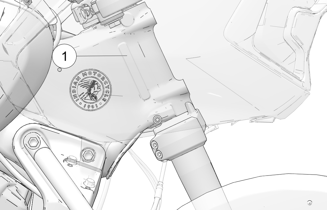
2.2.15.1: Vehicle Identification Number (VIN)
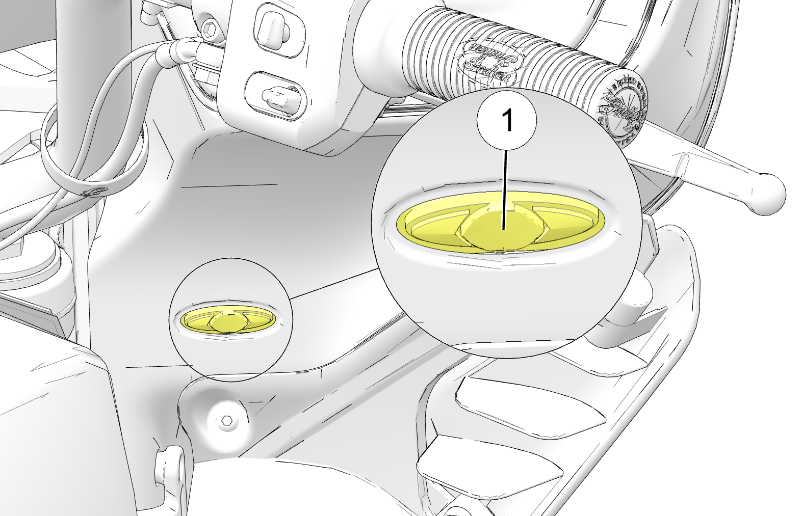
The Vehicle Identification Number (VIN) label 1 is stamped
on the right side of steering head.
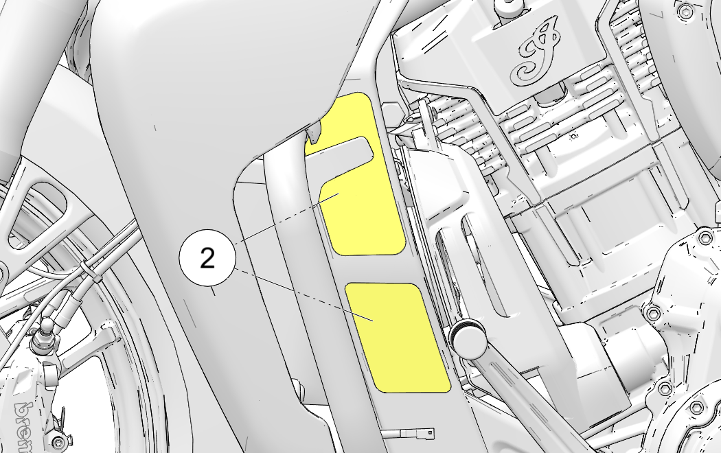
2.2.15.2: Vehicle Emission Control Information (VECI) and Noise Emission
Control Information (NECI)
The Vehicle Emission Control Information (VECI) and Noise Emission
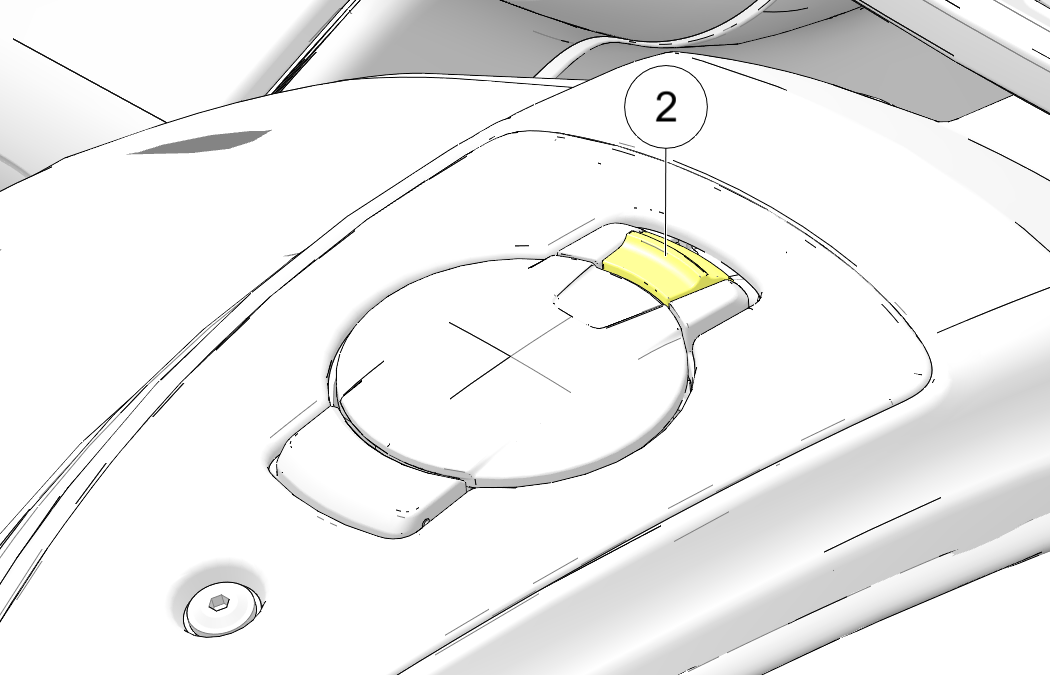
Control Information (NECI) label 2 is located on the left-hand
side of the motorcycle.
108 ci
112 ci
Part Number:
7301033 English, 7301034 French
7301035 English, 7301036 French
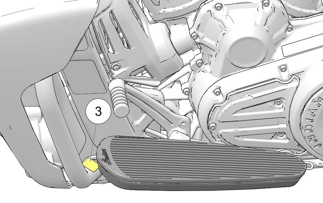
2.2.15.3: Highway Bar Warning
The highway bar warning label 3 is located on the lower
portion of the left highway bar.
WARNING
Highway bar is not designed to protect you from injury in a collision.
Part Number: 7176355 English, 7300541 Japanese, 7300613 Chinese
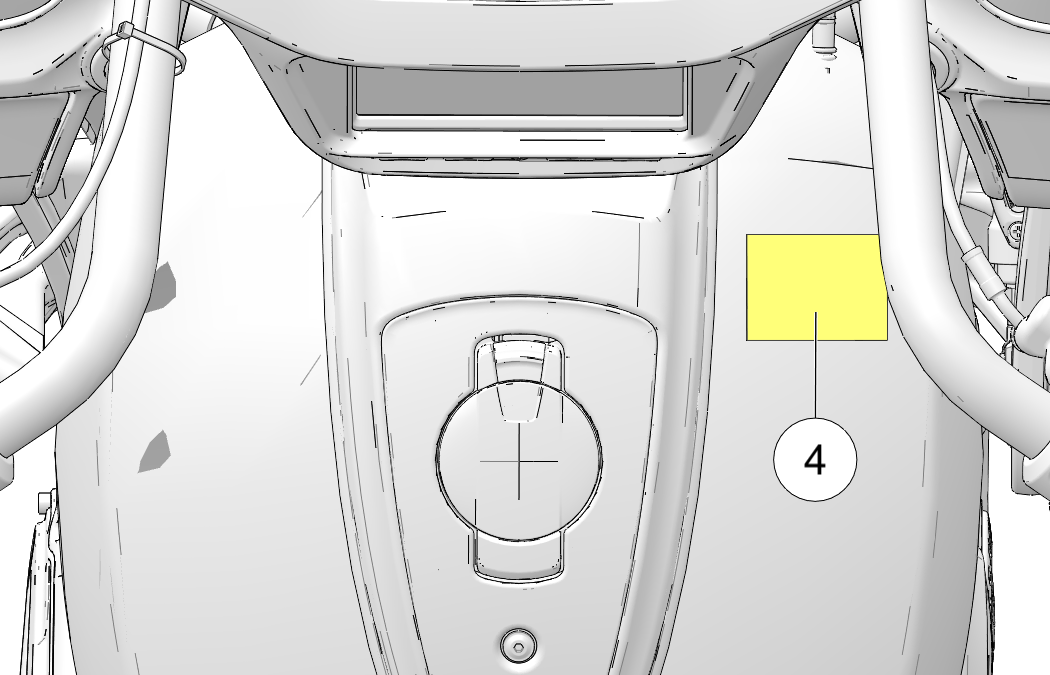
2.2.15.4: Operator Warning/Fuel Recommendation
The Operator Warning/Fuel Recommendation safety label 4 is located on the fuel tank.
WARNING
Read Owner’s Manual and, during use, follow all safety
precautions.
Always wear an approved helmet, eye protection and protective
clothing.
If your Owner’s Manual is missing, contact an Indian
Motorcycle dealer for a replacement.
CAUTION
Never overfill fuel tank. Fuel level should not rise into fill
neck funnel. Overfilling may result in degraded performance of engine
and evaporative emission control system.
Part Number: 7300004 English, 7300035 English (Europe), 7300041
French, 7300334 Japanese
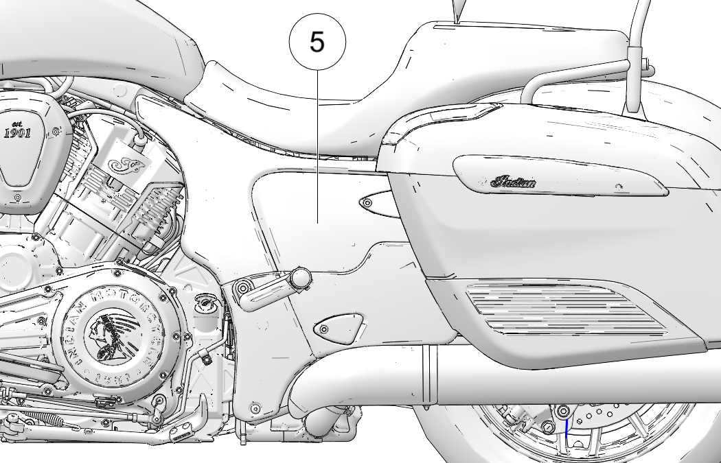
2.2.15.5: Rear Shock Hydraulic Adjustment Setting
The Rear Shock Hydraulic Adjustment Setting 5 is located
on the inside of the side cover.
Shock: Hydraulic Adjustment Setting
Total Cargo + Riders (lbs)
No Trunk Settings
Painted Trunk Settings
150
1
3
CAUTION: DO
NOT USE IMPACT TOOLS OR EXCEED 10 FT-LBS OF TORQUE WHEN ADJUSTING.
DAMAGE TO COMPONENTS MAY OCCUR.
175
1
3
200
2
3
225
2
4
250
2
4
275
3
5
300
3
5
325
3
6
350
4
6
375
4
7
400
4
7
425
4
8
450
5
8
475
5
N/A
500
5
N/A
Part Number: 7195533 English
Shock: Hydraulic Adjustment Setting
Total Cargo + Riders (kg)
No Trunk Settings
Painted Trunk Settings
68
1
3
CAUTION: DO
NOT USE IMPACT TOOLS OR EXCEED 14 N•m OF TORQUE WHEN ADJUSTING.
DAMAGE TO COMPONENTS MAY OCCUR.
79
1
3
91
2
3
102
2
4
113
2
4
125
3
5
136
3
5
147
3
6
159
4
6
170
4
7
181
4
7
193
4
8
204
5
8
215
5
N/A
227
5
N/A
Part Number: 7300358 Japanese, 7301112 Chinese
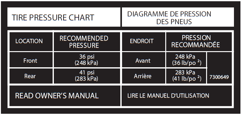
2.2.15.6: Tire Pressure Chart
The Tire Pressure Chart is located inside the saddlebag. Part Number: 7300649 English, 7300651 Chinese, 7300653 Japanese
TIRE PRESSURE CHART
DIAGRAMME DE PRESSION
DES PNEUS
LOCATION
RECOMMENDED PRESSURE
ENDROIT
PRESSION RECOMMANDÉE
Front
36 psi (248 kpa)
Avant
(248 kpa) (36 lb/po²)
7300649
Rear
41 psi (283 kpa)
Arrière
(283 kpa) (41 lb/po²)
READ OWNER’S MANUAL
LIRE LE MANUEL D’UTILISATION
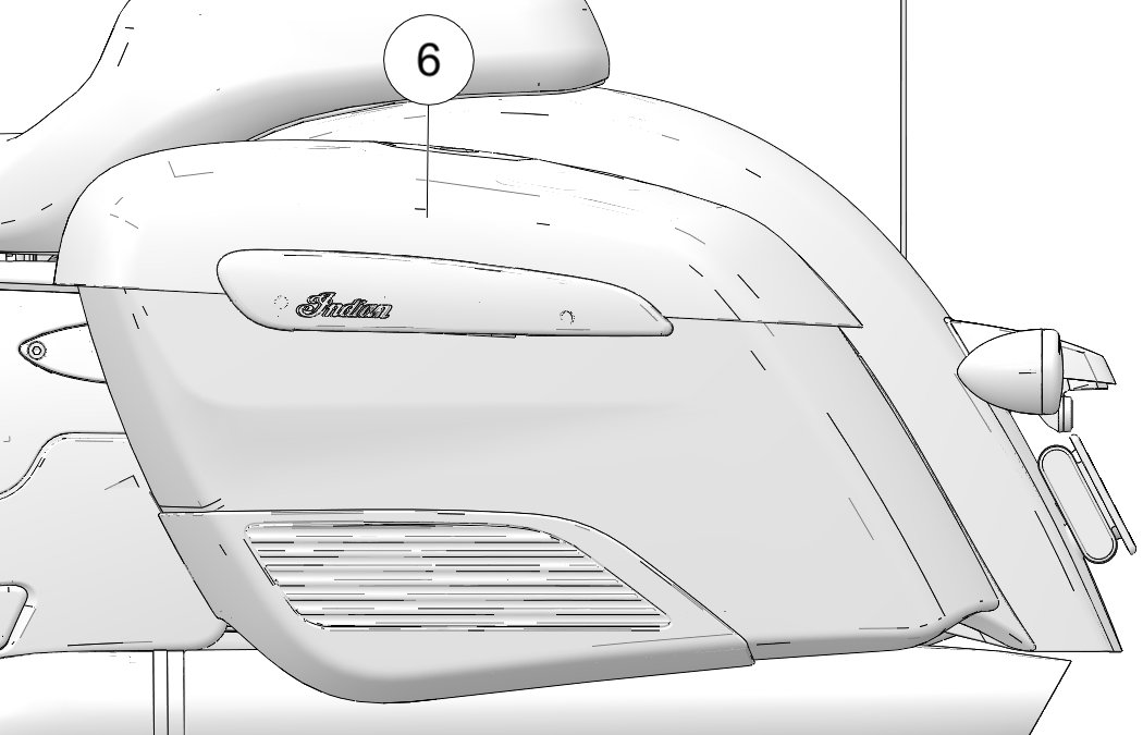
2.2.15.7: Cargo Limit Warning
The Cargo Limit warning label 6 is located inside the
saddlebag.
WARNING
CARGO LIMIT: 10 kg / 22.0 lbs.
Including optional lid rack cargo. Lid rack cargo limit 2.2 kg
/ 5.0 lbs. Including any optional accessory. Distribute weight evenly
on both sides of the vehicle. Total weight of rider, passenger, accessories,
and cargo must not exceed gross vehicle rating in owner’s manual.
Part Number: 7179868 English, 7300357 Japanese, 7300615 Chinese
2.2.15.8: Trunk Cargo Limit Warning
WARNING
CARGO LIMIT: 13.6 kg / 30.0 lbs.
Including optional lid rack and cargo lid rack cargo limit 2.2
kg / 5.0 lbs.
Open saddlebag lids before removal or installation of trunk to
prevent paint damage.
Part Number: 7180928 English
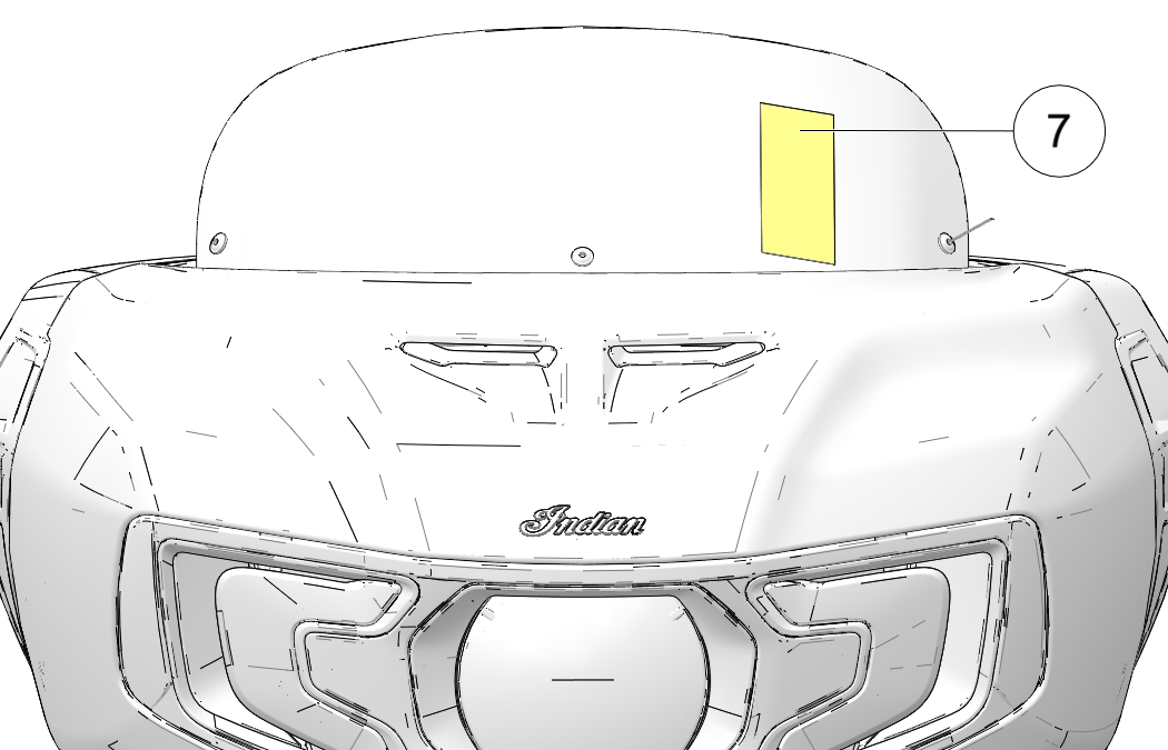
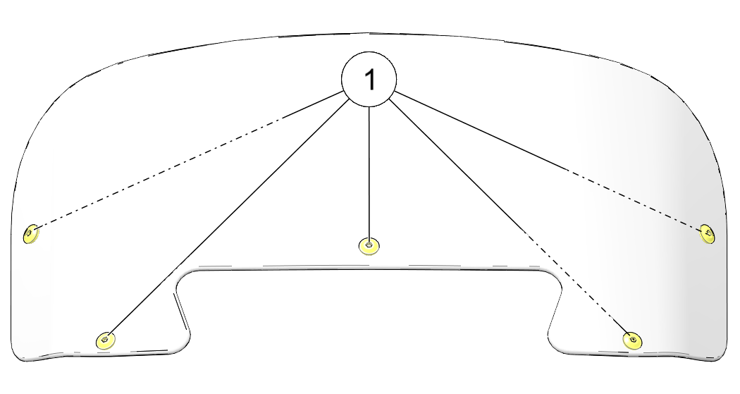
2.2.15.9: Windshield Warning
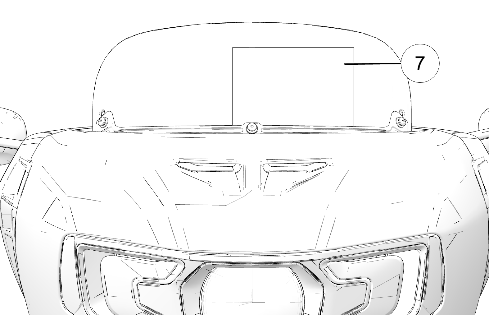
The windshield warning label 7 is located on the vehicle’s
windshield.
ATTENTION: This item to be removed by customer only.
WARNING
Do not ride with a damaged, loose, or improperly fitted windshield/wind-deflector.
These conditions can reduce visibility, affect handling, or cause
a loss of control.
Regularly check the parts for damage and looseness. If you
encounter an issue, contact your dealer.
Windshields/wind-deflectors will not protect the rider in a
collision.
Dark/Smoked wind-deflectors will reduce visibility in low-light
riding conditions.
CAUTION
Brake fluid and alcohol will permanently damage the polycarbonate
windshield.
Do not clean the windshield/wind-deflector with glass cleaners
or rain protective products.
CLEANING
Clean windshield or wind-deflector with a soft cloth and plenty
of warm water. Dry with a soft clean cloth. Remove minor scratches
with a quality plastic polishing compound.
See windshield/wind-deflector installation instructions and
the Owner’s Manual for complete instructions on the proper
care of your windshield or wind-deflector.
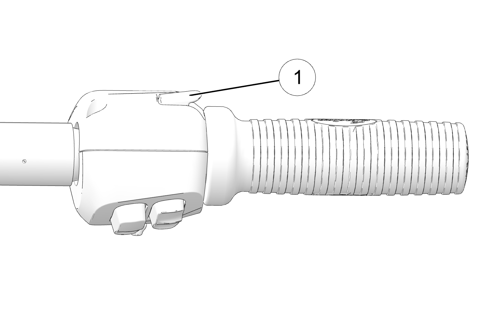
All models are equipped with toggle switches on the front side
of the left and right 1 handlebar controls.
The power switch must be ON for the toggle switches to function.
Use the right-hand switch to navigate through menus or accept dialog
boxes on the Ride Command display. Use the left-hand switch to back
out of menus, decline dialog boxes, hang up phone calls, and toggle
through display screens.
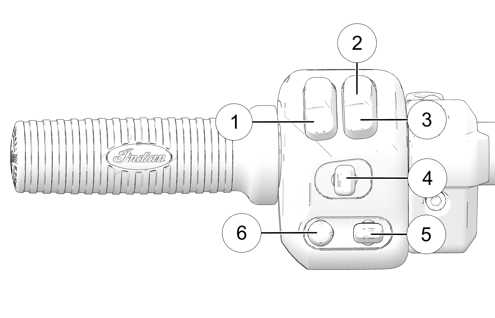
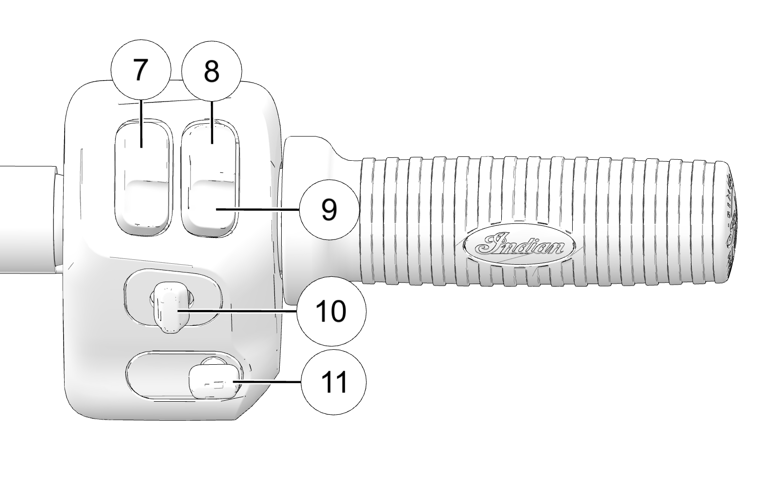
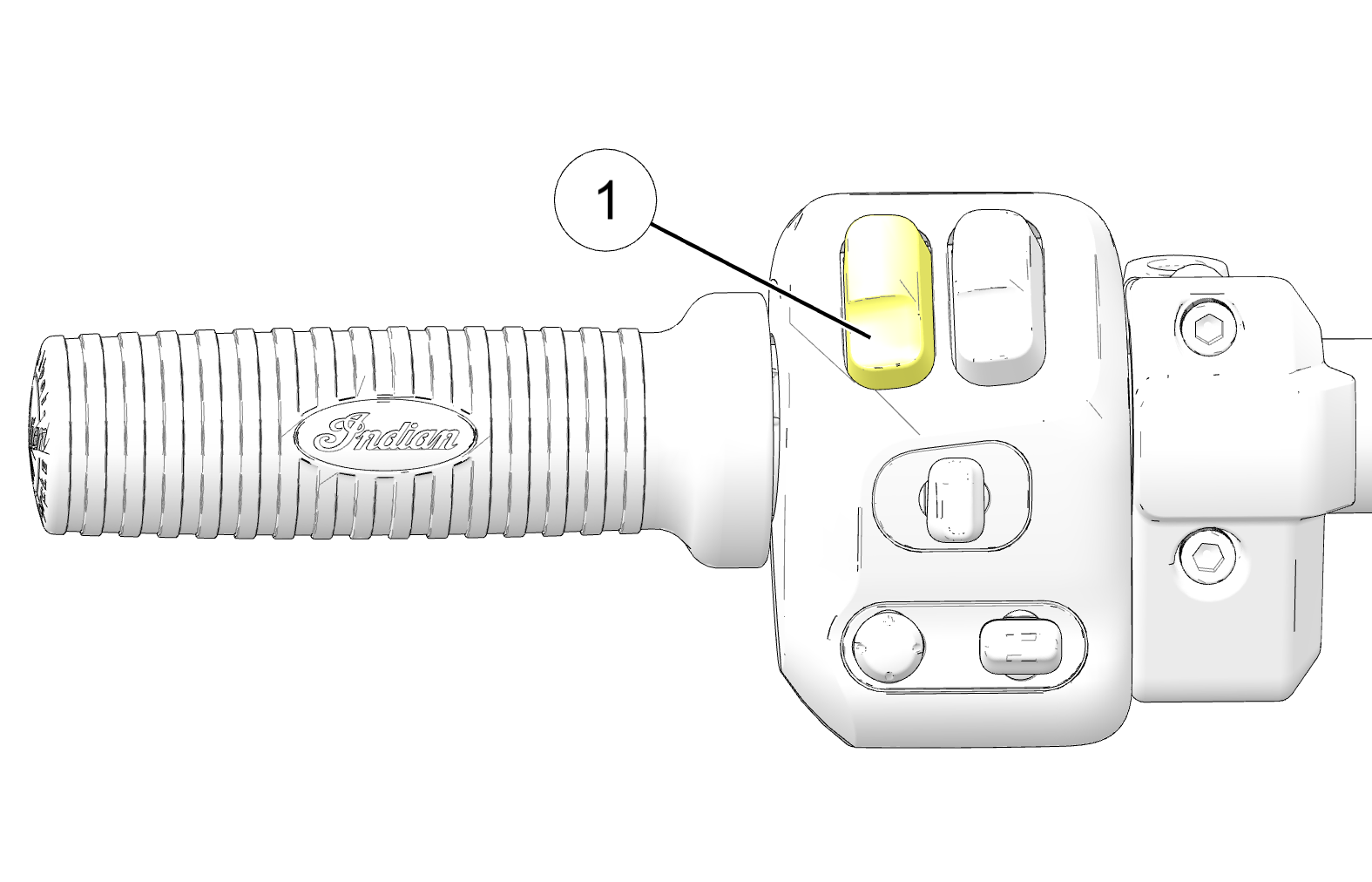
The low headlight beam switch activates the low
headlight beam. Press down momentarily to activate Flash to Pass.
See High/Low Headlight Beam Switch.
Turn Signal Switch
Move the switch to the left to activate the left
turn signals. Move the switch to the right to activate the right turn
signals. A signal will deactivate automatically when speed or distance
reach predetermined levels. To cancel a signal manually, move the
switch to the center position and push it inward.Momentary Feature:Move the turn signal switch left or right and hold it in that
position for at least one second. The momentary feature will activate
and the signal will then cancel when the switch is released.
Emergency Flasher Switch (Hazard Switch)
The hazard switch activates and cancels the emergency
flashers when pressed. See Hazard Switch.
Screen List Select Switch
The Screen List Select Switch (if equipped) is
used to navigate through rider screens.
Up/down rocker
Press to select
Long press to open controls
Audio Control Switch
The Audio Control Switch allows users to control
the audio system features from the left control block.
Volume up/down rocker
Track previous/next rocker
Press to mute/pause
Long press to trigger Push to Talk
Stop Switch
Press the bottom of the switch (RUN) to allow
the engine to start and run. Press the top of the switch (STOP) to
stop the engine. See Engine Stop/Run Switch.
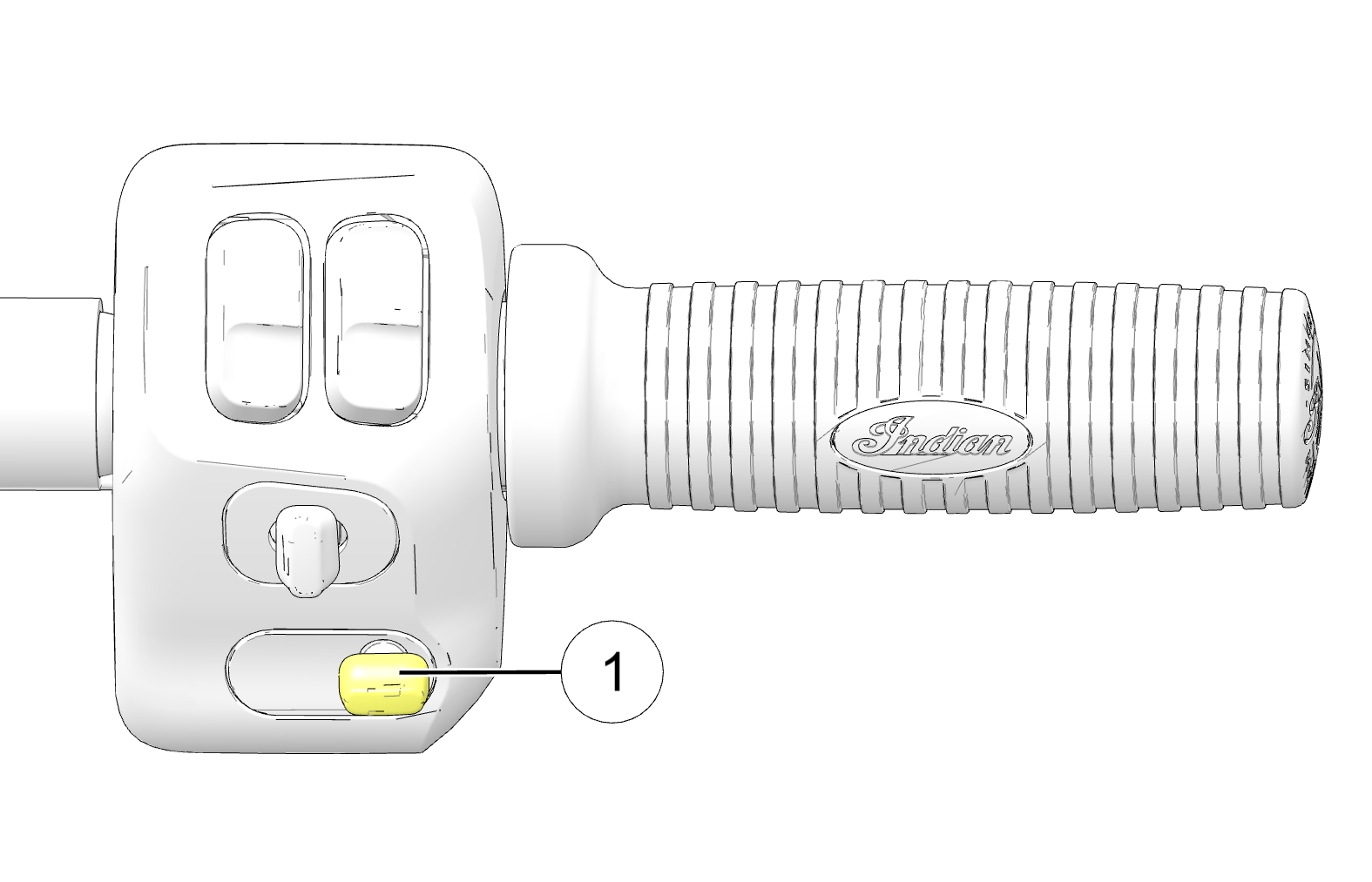
Starter Switch
Use the starter switch to start the engine. The
engine stop/run switch must be in the RUN position. See Engine Stop/Run Switch.
Power Switch
Press and release the power switch to enable or
disable all electrical power to the vehicle. See Power Switch.
Left-Hand Trigger Switch
Use the left-hand switch to back out of menus,
decline dialog boxes, hang up phone calls, and toggle through display
screens. See Toggle Switches.
Right-Hand Trigger Switch
Use the right-hand switch to navigate through
menus or accept dialog boxes on Ride Command display.
3.3.5: Switches
3.3.5.1: Power Switch
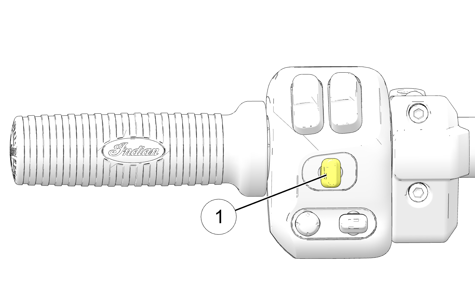
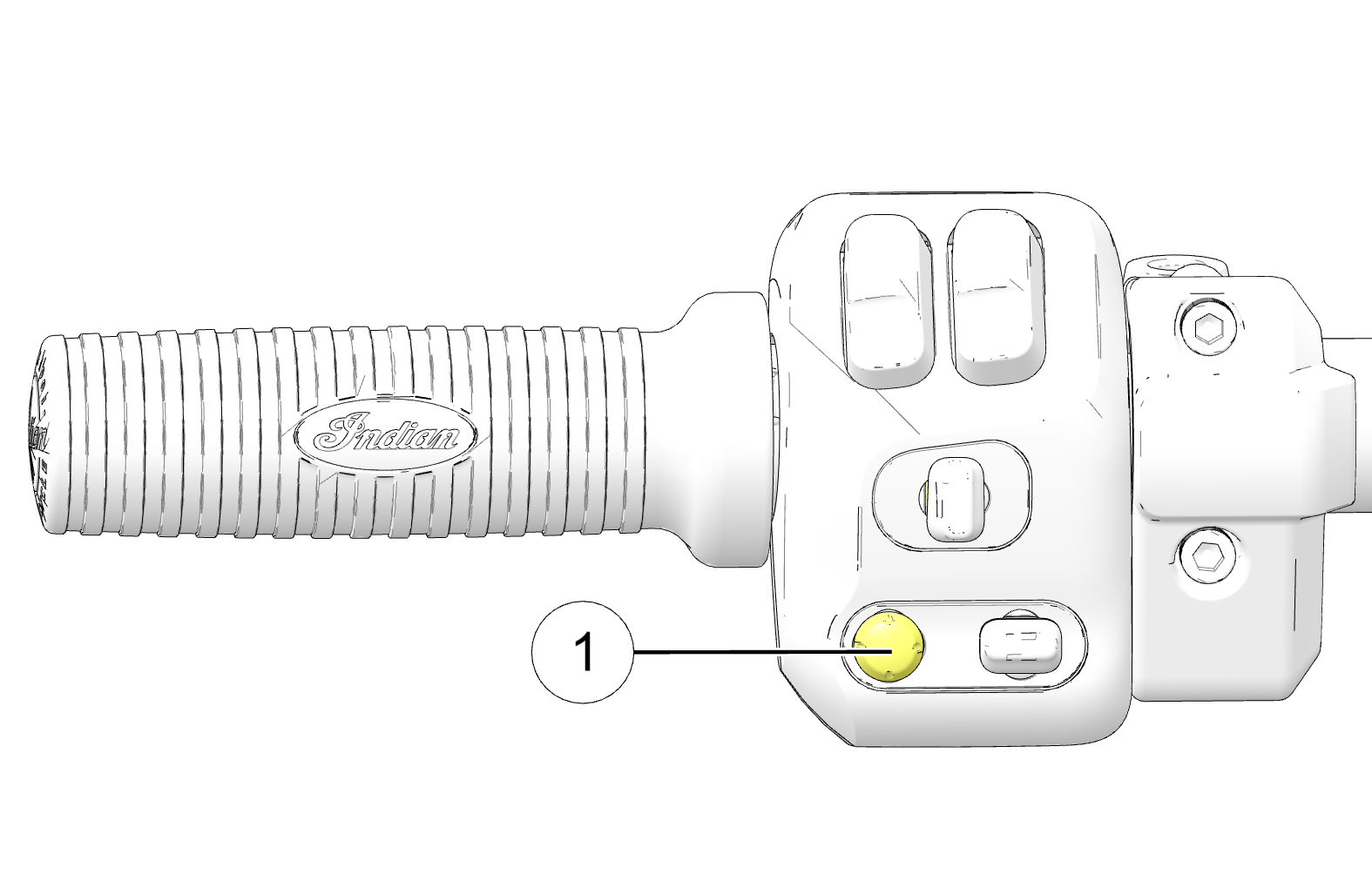
The power switch is located on the right control 1. Press
and release the power switch to enable or disable all electrical power
to the vehicle.
To disable all electrical power if the motorcycle is moving and
the engine is running, press and hold the power switch for more than
three seconds. This will also turn the engine off.
NOTICE
The headlights and any accessories plugged into
power ports will remain on until the power switch is turned off.
NOTICE
To save battery power, the vehicle will automatically
power off after five minutes of inactivity. Automatic power down can
be overridden on bikes equipped with an INDIAN MOTORCYCLE Ride Command
display through the Vehicle Settings menu.
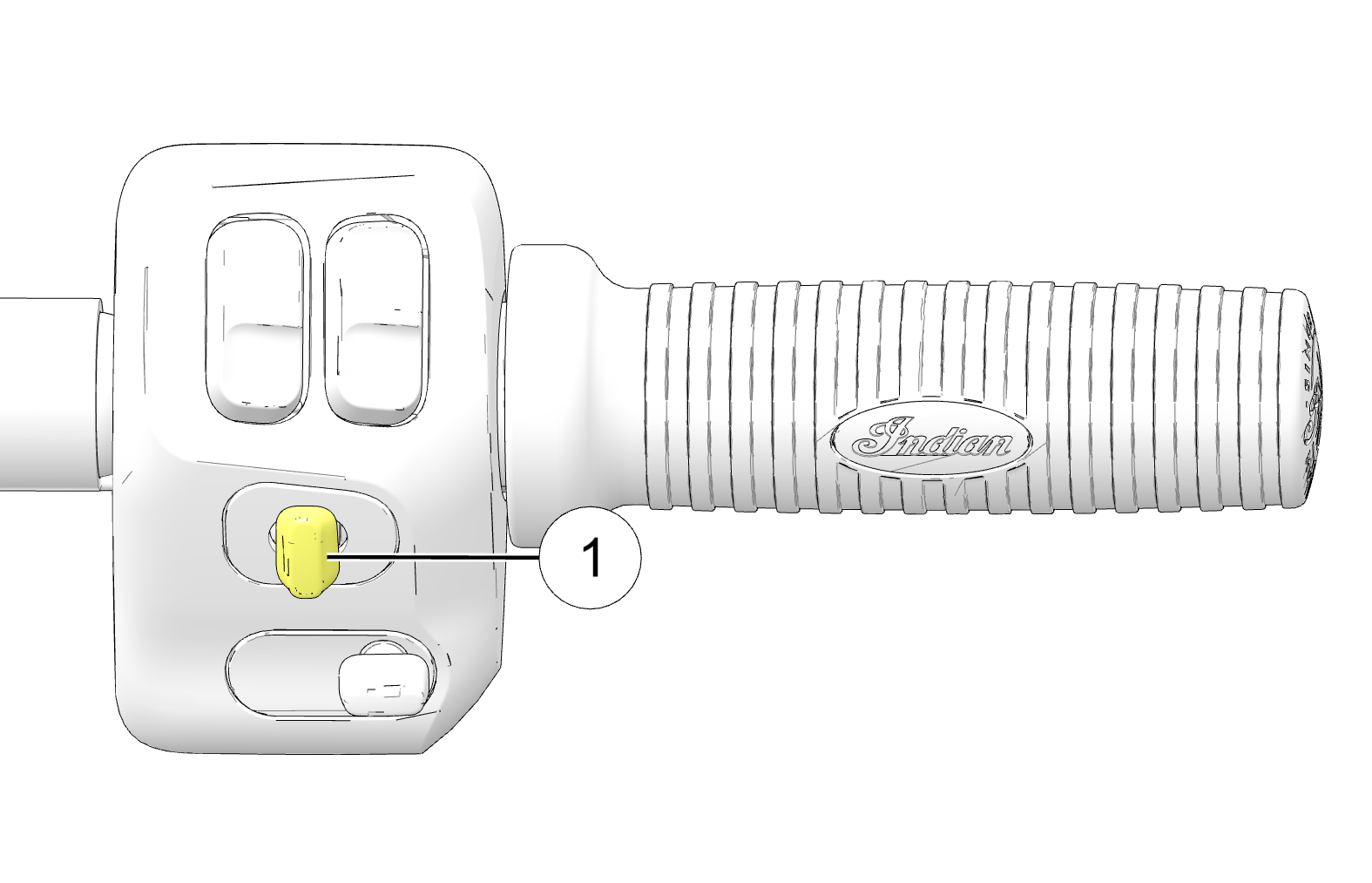
3.3.5.2: Engine Stop/Run Switch
Use the engine stop/run switch to turn the engine off quickly.
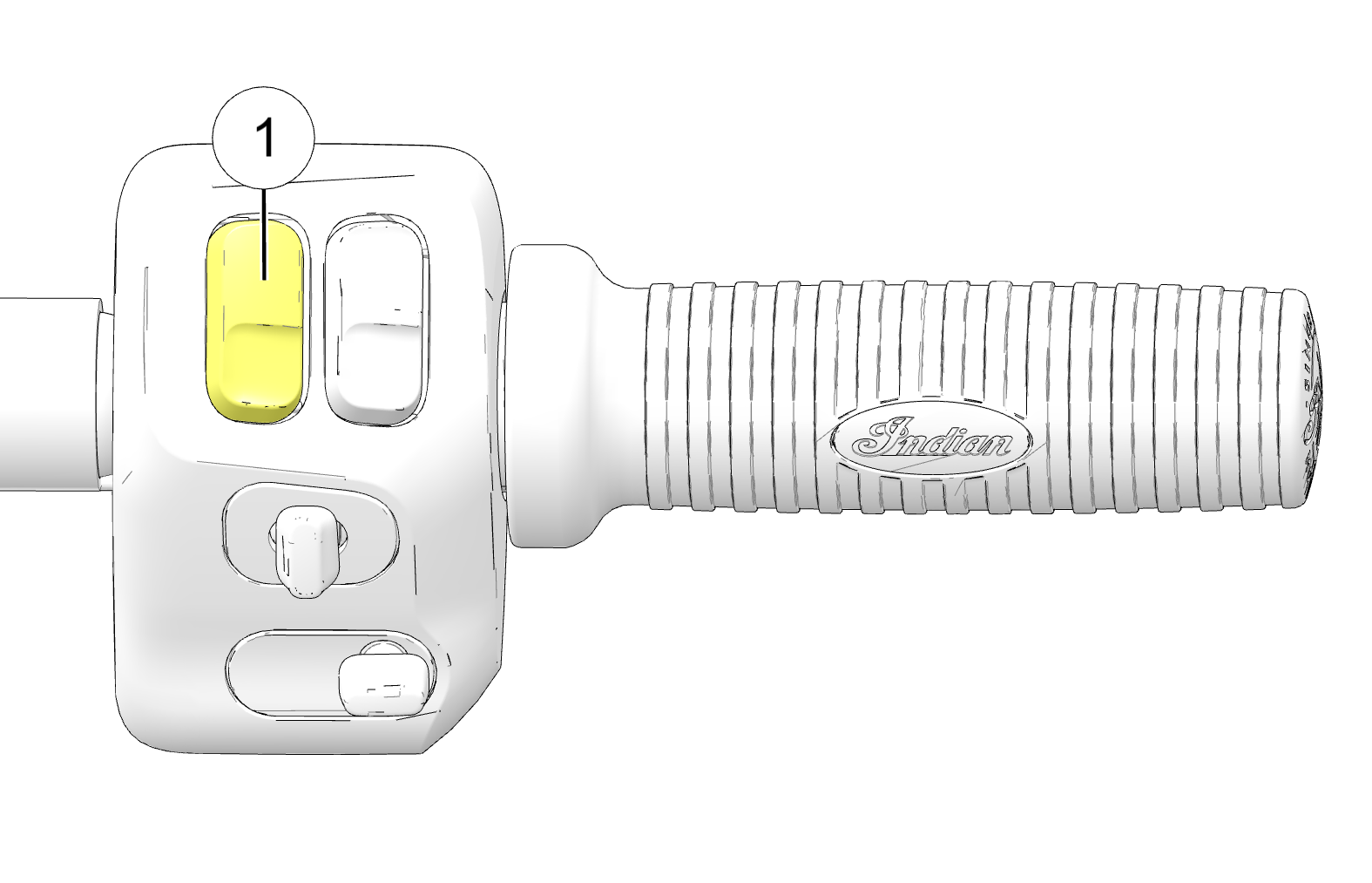
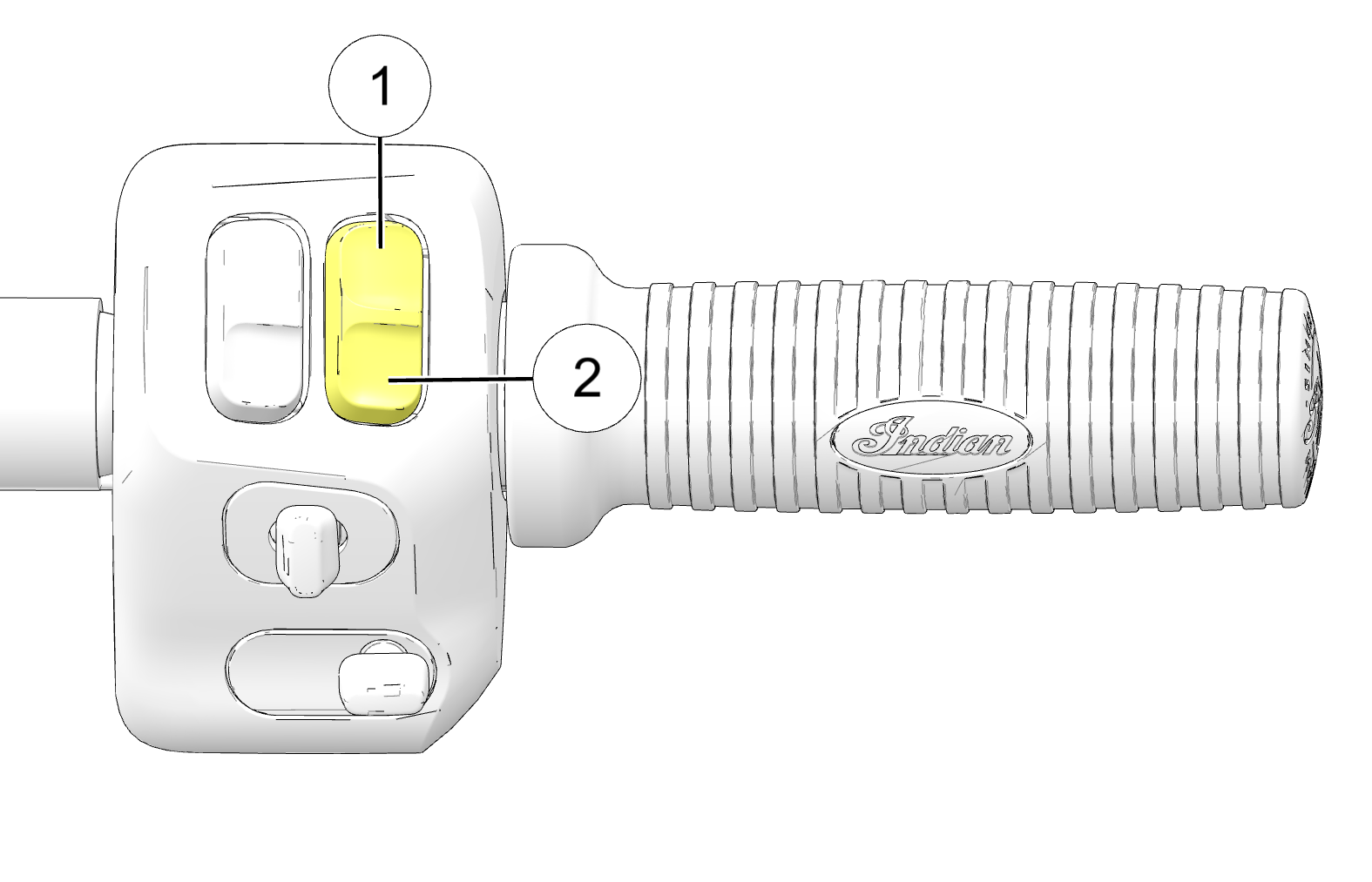
Press the top of the switch (STOP) 1 to interrupt the
circuits and stop the engine. The engine should not start or run when
the switch is in the STOP position.
Press the bottom of the switch (RUN) 2 to complete the
circuits and allow the engine to start and run. Press and Release
the bottom switch (RUN) 2 to start the engine.
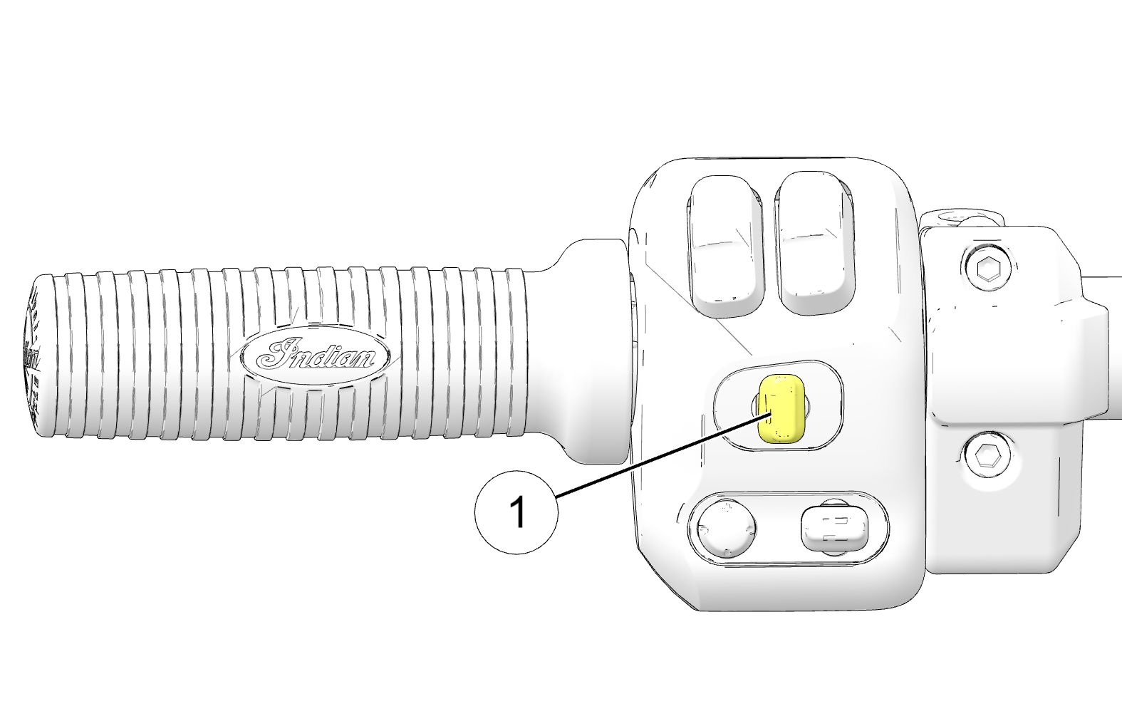
3.3.5.3: Cruise Control Switch
Cruise control can be activated and adjusted from the right control
using the Cruise Control Switch 1. For more information about
Cruise Control, see Using Cruise Control.
Toggle Position
Function
Left
Set/Decelerate
Center
Off/On
Right
Resume/Accelerate
3.3.5.4: Windshield Switch
Use the windshield switch 1 to adjust windshield height
for the best wind deflection.
Press up on the switch to adjust the windshield upward. Press down
on the switch to adjust the windshield downward. Double tap up or
down on the switch to auto-adjust the windshield all the way up or
down. If the windshield is traveling and the opposite direction is
briefly pressed, the auto travel is canceled.
3.3.5.5: High/Low Headlight Beam Switch
The headlights automatically come on when the engine is started.
See Headlights.
The high/low headlight beam switch toggles the headlight between
high beam and low beam. To activate the high beam, press the upper
portion of the switch. To activate the low beam, press the lower portion
of the switch. To momentarily flash headlights (Flash to Pass), press
and hold the lower portion of the switch.
3.3.5.6: Horn Switch
Press the horn switch 1 to sound the horn.
3.3.5.7: Hazard Switch
The power switch must be ON to activate the flashers, but once
activated, the flashers will continue to flash when the power switch
is turned off. When the flashers are active, all four turn signals
flash.
To activate the hazard switch, press on the center of the turn
signal switch 1.
Press and hold the switch to activate the flashers.
Press the switch again to cancel the flashers.
3.3.5.8: Turn Signal
Move the switch 1 to the left to activate the left turn
signals. Move the switch 1 to the right to activate the right
turn signals. A signal will deactivate automatically when speed or
distance reach predetermined levels. To cancel a signal manually,
move the switch to the center position and push it inward. Momentary
Feature: Move the turn signal switch left or right and hold it in
that position for at least one second. The momentary feature will
activate and the signal will then cancel when the switch is released.
One arrow flashes when the corresponding turn signal is activated.
Both arrows flash when the hazard signal is activated. If there
is a problem in the signal system, the lamps will flash at twice the
normal rate.
3.3.5.9: Audio Control Switch
The Audio Control Switch 1 allows users to control the
audio system features from the left control block.
Volume
To increase volume, press up on the
audio control switch. To decrease the volume, press down on the audio
control switch. To mute the volume, push in on the audio control switch.
NOTICE
When using a Bluetooth® audio device, pushing
in on the audio control switch will pause the audio. To resume, press
in on the audio control switch again.
Tuner
When the audio source is set to Tuner,
press left or right to navigate through preset stations. Press and
hold to seek.
Personal Audio
When audio source is set
to Bluetooth® Audio or USB, press left or right to navigate through
audio tracks.
3.3.5.10: Auxiliary Light Switch (if equipped)
The auxiliary lights provide additional lighting on each side of
the headlight. Some drivers prefer using the auxiliary lights when
operating in foggy conditions or when passing a vehicle to help improve
visibility to other motorists.
Use the Ride Command Control Panel to turn the auxiliary lights
on or off.
A green icon will show along the top bar when the auxiliary lights
are on. The auxiliary lights turn off when the power switch is turned
off. The auxiliary lights automatically turn on when the engine starts
if they were on when the engine was shut down.
To control when the auxiliary light is enabled / disabled, use
the auxiliary light settings page.
3.3.5.11: Keyless Ignition
WARNING
Keep the key fob and key fob battery out of reach
of children. Swallowing can lead to chemical burns, perforation of
soft tissue, and death. Severe burns can occur within 2 hours of ingestion.
Seek medical attention immediately.
Starting Key Fob Operation:
When the electrical
system is activated with the power switch, the key fob must be within
range. If the key fob is not detected, the security light will flash.
The electrical system will automatically shut down.
The starter
motor will not engage during this time. If a key fob is not available,
your personal identification number (PIN) can be entered using the
turn signal switches, or on the Ride Command display screen (if equipped),
to unlock the security system.
Driving Key Fob Operation:
After starting
the engine, the Vehicle Control Module (WCM) will again verify that
the key fob is within range when exceeding 5 mph for the first time.
The security light may turn on during this check. The WCM will not
search for the key fob again after the vehicle has exceeded 5 mph.
If the key fob is lost during riding, the PIN will be needed to restart
the vehicle.
If the key fob is not detected when exceeding
5 mph:
The security light will flash.
The engine will continue to run for that drive cycle.
Once shutdown, will require PIN or key fob to restart.
Key Fob Storage:
The key fob should not
be stored in the phone storage compartment, or near devices that can
interfere with radio waves, such as cell phones, power supplies, or
magnets, during operation.
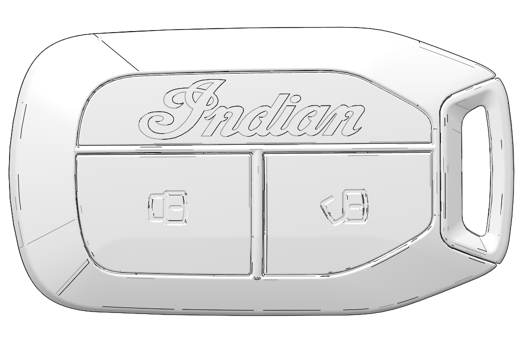
Alarm System:
The alarm feature can be activated
using the multi-function, two-button key fob. The alarm system is
not available on vehicles with a buttonless fob.
To activate
the alarm, press the LOCK button on the key fob two times. The horn
will sound briefly to confirm that the alarm is activated.
To
deactivate the alarm, make sure your key fob is within range. Then
do one of five things:
Press the UNLOCK button on the key fob.
Press the power button on the console panel.
Press the starter button.
Press the LOCK/UNLOCK switch on the center console.
Move the motorcycle to the fully upright position from leaning
on the sidestand. The horn will sound repeatedly if the key fob is
not detected within 5 seconds.
3.3.5.12: Saddlebag Lock Switch (if equipped)
Use the key fob or the lock switch on the console to lock and unlock
the electric saddlebag locks. When using the console lock switch,
the key fob must be within range. If the key fob is not detected,
the security light and/or power switch will flash. The system will
not perform the lock or unlock command.
3.3.5.13: Heated Seat Switches (if equipped)
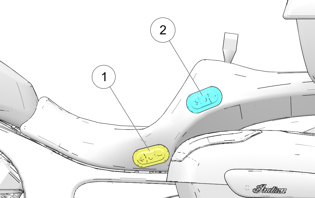
Use the seat switches located on the lower left
edge of the seat to adjust heating settings. The front switch 1 controls the settings for the driver seat, and the rear switch
(if equipped) 2 controls the passenger seat setting. A brief
pop-up will appear on the Ride Command touchscreen display when heat
level is changed. For more information, see Heated Seats Heat Level Setting (if equipped). Seats
will remain off until activated with switch. Both red and blue LED
lights remain dimly lit when off. To turn off, press center OFF switch.
IMPORTANT
The heated seat will only operate if the
engine is on.
WARNING
Users who have compromised senses and are
unable to feel temperature change or pain to the skin should use extra
care when using the seat heater. The seat heater may cause burns even
at low temperatures especially when used for long periods of time.
Do not place anything on the seat that insulates against heat
such as blankets or cushions. This may cause the seat heater to overheat
which may cause a burn or damage to the seat.
Heating
Press Red switch to increase heat mode from LOW to MEDIUM to
HIGH.
Press and hold Red switch for two seconds to skip straight
to HIGH.
Press Blue switch to decrease heat mode from HIGH to MEDIUM
to LOW.
NOTICE
When in heat mode, Red LED will be brightly
lit and fans in cushions will be off.
3.3.5.14: Heated and Cooled Seat Switches (if equipped)
Use the seat switches located on the lower left
edge of the seat to adjust heating and cooling settings. The front
switch 1 controls the settings for the driver seat, and the
rear switch (if equipped) 2 controls the passenger seat setting.
A brief pop-up will appear on the Ride Command touchscreen display
when heat or cool level is changed. For more information, see Heated Seats Heat Level Setting (if equipped). Seats will remain off until activated with switch. Both
red and blue LED lights remain dimly lit when off. To turn off, press
center OFF switch.
IMPORTANT
The heated and cooled seat will only operate
if the engine is on.
WARNING
Users who have compromised senses and are
unable to feel temperature change or pain to the skin should use extra
care when using the seat heater. The seat heater may cause burns even
at low temperatures especially when used for long periods of time.
Do not place anything on the seat that insulates against heat
such as blankets or cushions. This may cause the seat heater to overheat
which may cause a burn or damage to the seat.
Cooling
Press Blue switch to increase cool mode from LOW to MEDIUM
to HIGH.
Press and hold Blue switch for two seconds to skip straight
to HIGH.
Press Red switch to decrease cool mode from HIGH to MEDIUM
to LOW.
NOTICE
When in cool mode, Blue LED will be brightly
lit and fans in cushions will be on.
Heating
Press Red switch to increase heat mode from LOW to MEDIUM to
HIGH.
Press and hold Red switch for two seconds to skip straight
to HIGH.
Press Blue switch to decrease heat mode from HIGH to MEDIUM
to LOW.
NOTICE
When in heat mode, Red LED will be brightly
lit and fans in cushions will be off.
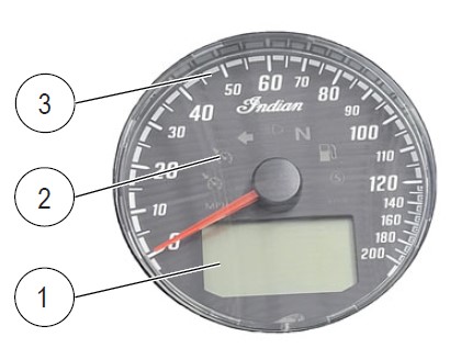
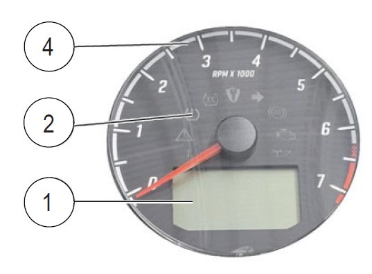
3.3.6: Instrument Cluster
1 Multi-function Display
2 Indicator Lamps
3 Speedometer
4 Tachometer
3.3.6.1: Indicator Lamps
Lamp
Indicates
Condition
Cruise Control Status
Amber Lamp: Cruise control is enabled, but not set.
When flashing, a cruise control related fault exists. Green Lamp: Cruise control is set to the desired speed. Read the safety and
operation procedures before using cruise control.
Turn Signals
One arrow flashes when the corresponding turn signal is activated.
Both arrows flash when the hazard signal is activated. If there
is a problem in the signal system, the lamps will flash at twice the
normal rate.
Vehicle Speed
When standard mode is selected, speed displays in miles per
hour.
When metric mode is selected, speed displays in kilometers
per hour.
High Beam
The headlight switch is set to high beam. This indicator will
flash if there is a problem with the low or high beam light.
Neutral
The transmission is in neutral and the power switch is ON.
Low Fuel
This lamp illuminates when approximately 1 gal (3.8 l) of fuel remains in the
fuel tank. The LCD Display will switch into a Low Fuel Mileage Counter
Mode to provide the rider with mileage tracking from the time the
indicator was activated.
Sidestand Light
The sidestand light will turn on anytime the sidestand is down.
Engine Hot
This lamp illuminates to indicate an overheated engine. If
the indicator flashes, a severe overheating condition exists.
Chassis Fault
The alert symbol illuminates if a chassis fault occurs.
Tire Pressure Monitoring System (TPMS)
The TPMS indicator illuminates if low tire pressure is detected.
It will also illuminate along with the Low Battery Voltage indicator
when TPMS battery power is low, requiring service.
Traction Control
This lamp will flash slowly when the power switch is turned
ON, which indicates that traction control is not yet available. Traction
control becomes available when the vehicle speed exceeds 3 mph (5
km/h) and the lamp will then turn off.
This lamp will flash
rapidly when the traction control system is actively limiting rear
wheel silp.
This lamp will illuminate and remain on if traction
control is disabled or has a fault.
Security
The security indicator illuminates when the security system
is activated.
ABS Not Activated
This lamp will flash slowly when the power switch is turned
ON, which indicates that the anti-lock brake system is not yet available.
The anti-lock brake system will be available when vehicle speed exceeds
3 mph (5 km/h) and the lamp will then turn off. This lamp will not
illuminate if the anti-lock braking system is working correctly and
actively limiting wheel lock. This lamp will illuminate and remain
on if the anti-lock braking system has a fault. The conventional brake
system will continue to operate normally during an ABS fault.
Check Engine
This lamp illuminates briefly when the power switch is turned
ON. This indicates proper function. If this lamp illuminates while
the engine is running, see an authorized dealer promptly. The
light will remain on if the tilt sensor shuts down the engine. If
abnormal sensor or engine operation is detected the light will remain
on as long as the fault condition exists. Retrieve the error codes
for diagnosis.
Low Oil Pressure
This lamp illuminates when oil pressure drops below a safe
operating pressure while the engine is running. If this lamp illuminates
while the engine is running above idle speed, turn the engine off
as soon as safely possible and check the oil level. If the oil
level is correct and the lamp remains on after the engine is restarted,
turn the engine off immediately. See your dealer.
3.3.6.2: Speedometer
The speedometer displays forward vehicle speed in either miles
per hour or kilometers per hour.
3.3.6.3: Tachometer
The tachometer displays engine speed in revolutions per minute
(RPM). A red line on the face of the gauge indicates the maximum safe
engine speed.
Excessive engine speed can cause engine damage or failure, which
could result in serious injury or death. Do not allow engine speed
to exceed the red line.
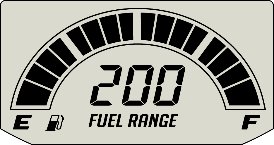
3.3.6.4: Fuel Gauge Display
The fuel gauge displays fuel level. For the most accurate reading,
sit on the motorcycle and bring it to the upright position for 2-3
minutes.
The segments of the fuel gauge show the level of fuel in the fuel
tank. When the last segment clears, a low fuel warning is activated.
All segments including the fuel icon will flash. Refuel promptly.
3.3.6.5: Rear Cylinder Deactivation
Designed as an aid to reduce engine and exhaust heat to the rider,
Rear Cylinder Deactivation turns off the rear cylinder when the engine
gets hot.
The following condition must be met for Rear Cylinder Deactivation
to be enabled.
Engine must be up to operating temperature
Ambient Temperature must exceed 59 f (15 c)
Engine speed must remain below 1000 RPM
Throttle must be in the closed position (0% throttle)
Exhaust catalyst temperature must be sufficiently high for
tailpipe emissions compliance.
NOTICE
If catalyst temperature drops below emissions
threshold the rear cylinder will re-engage until the catalyst temperature
rises above the threshold at which point the rear will deactivate
again.
Cylinder Deactivation can be turned off by accessing the settings
menu in the drop-down from the top of the screen. Cylinder Deactivation
controls are in the Vehicle menu. When Rear Cylinder Deactivation
is functioning, an icon will illuminate at the top of the Ride Command
display screen.
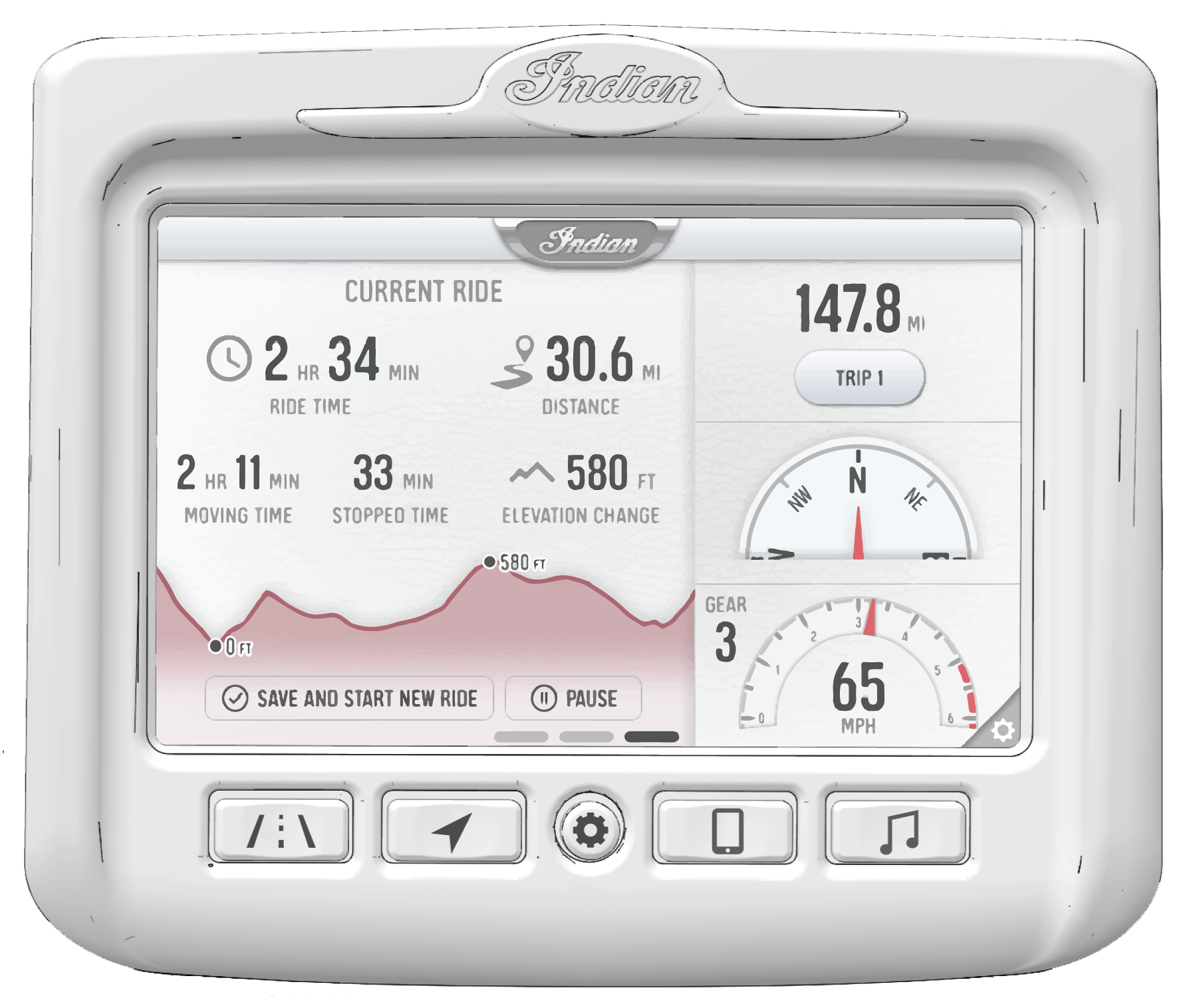
3.3.7: 7" Display Powered by RIDE COMMAND
3.3.7.1: Overview
For the latest information about the INDIAN MOTORCYCLE Ride Command
display, including software updates, please visit https://ridecommand.indianmotorcycle.com
NOTICE
Using the display for an extended period of time
while the vehicle’s engine is off can drain the battery.
WARNING
Do not enter information while operating your
vehicle. Failure to pay attention to operating your vehicle could
result in loss of control, injury, or death. You assume all risks
associated with using this device. Read your User Guide.
WARNING
Driving while distracted can result in loss of
vehicle control, crash, and injury. We strongly recommend that you
use extreme caution when using any device that may take your focus
off the road. Your primary responsibility is the safe operation of
your vehicle. We recommend against the use of any hand-held device
while driving and encourage the use of voice-operated systems when
possible. Make sure you are aware of all applicable local laws that
may affect the use of electronic devices while driving.
Before riding with your new display, do the following:
Read this entire manual.
Familiarize yourself with the features and operations of the
display while the vehicle is stationary.
Download the INDIAN MOTORCYCLE app from the Apple® App
Store® or Google Play® store and create your personalized
account.
Check https://www.indianmotorcycle.com/en-us/owners-manuals/ for the latest updates to the owner’s manual.
3.3.7.2: Ride Command Buttons
Button
Function
Rider Screens
Press the Rider Screens button to access the customizable
split screen menu system, access to ride data, vehicle status, and
vehicle information.
Navigation
Press the Navigation button to access Ride Command navigation
features (if equipped), find directions, and look up addresses, gas
stations, and other points of interest.
Controls
Press the Controls Button to access the INDIAN MOTORCYCLE
Badge Panel and additional settings.
Phone
Press the Phone button to pair a phone or headset to the
INDIAN MOTORCYCLE Ride Command display.
Audio
Press the Audio Button to change the audio source, adjust
volume level, and set radio presets.
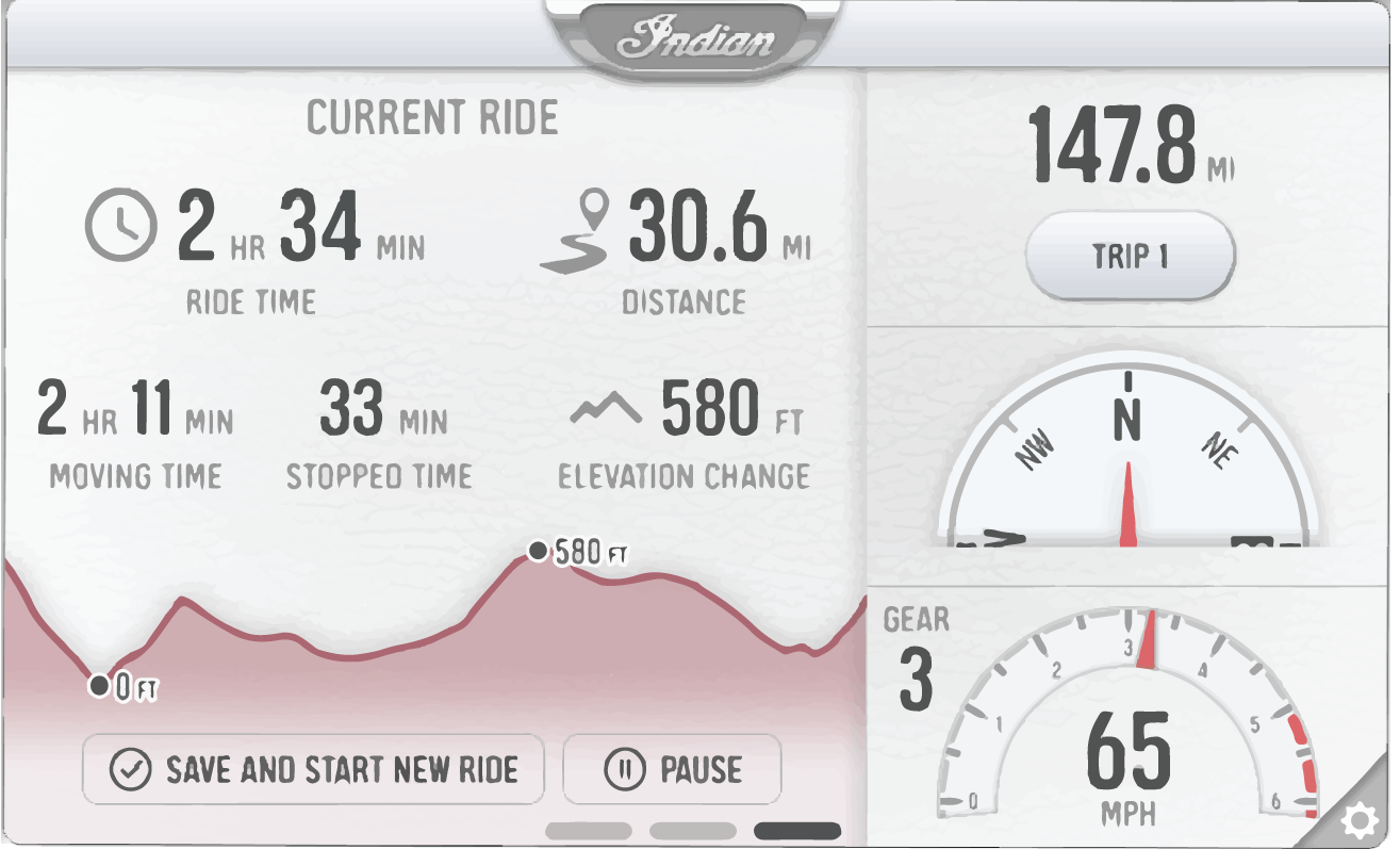
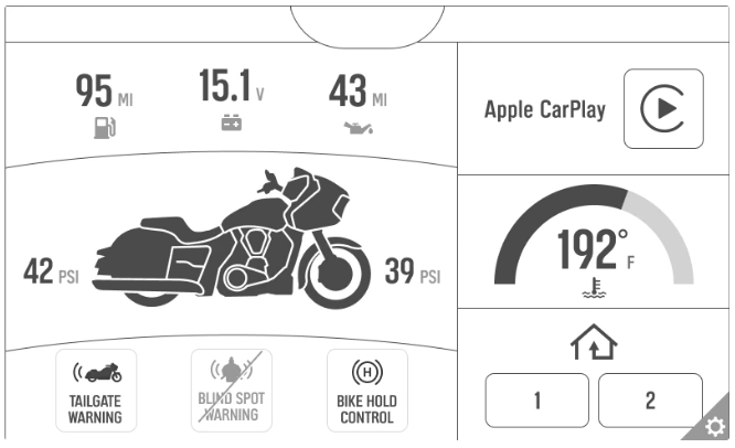
3.3.7.2.1: Rider Screens
The Rider Screens are customizable and provide
unique access to ride data, vehicle status, and vehicle information.
The Rider Screens also provide easy access to other often used features,
such as Audio controls, Bluetooth® features, and Maps.
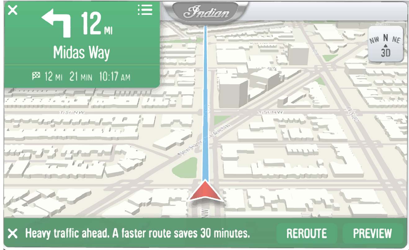
3.3.7.2.2: Navigation
Press the Navigation button to access Ride Command
navigation features (if equipped), find directions, and look up addresses,
gas stations, and other points of interest.
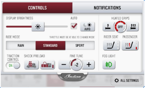
3.3.7.2.3: Control Panel
From the Control Panel you can access settings, adjust display
brightness, select ride mode, and vehicle climate controls.
You can access the Control Panel at anytime by pressing
the gear button on the display.
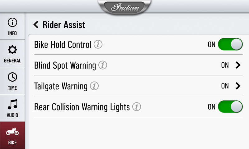
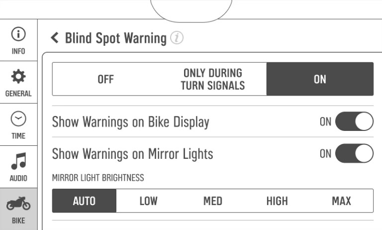
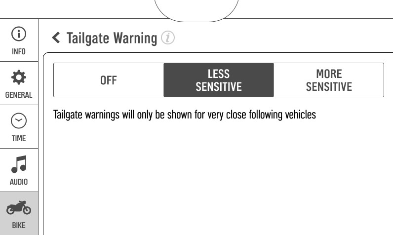
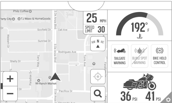
3.3.7.2.4: Rider Assist Controls
Select Rider Assist to change the Bike Hold Control,
Blind Spot Warning, Tailgate Warning, and Rear Collision Warning Light
settings.
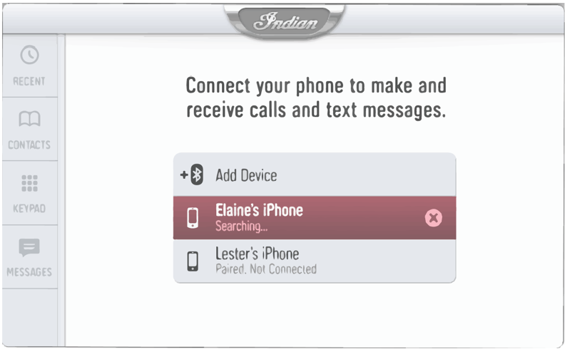
3.3.7.2.5: Phone
The Phone screen displays recent calls, contact list, key
pad, and messages. The display will only show messages received while
smartphone is paired via Bluetooth®.
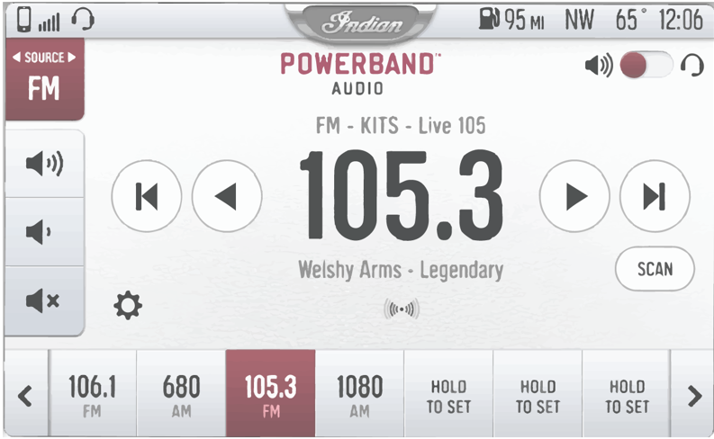
3.3.7.2.6: Audio Screen
The Audio screen allows you to access music stored
on your smart-phone or other music device. You can pair your device
using Bluetooth®, or by connecting it to the display’s
USB port.
USB audio playback is only available on flash drives
formatted to exFAT® or FAT32.
3.3.7.3: Ride Command Hand Controls
3.3.7.3.1: Media Switch
Use the 5–way media switch 1 to do the following:
Press center to mute
Press up/down to increase/decrease volume.
Press left/right to move to previous/next track.
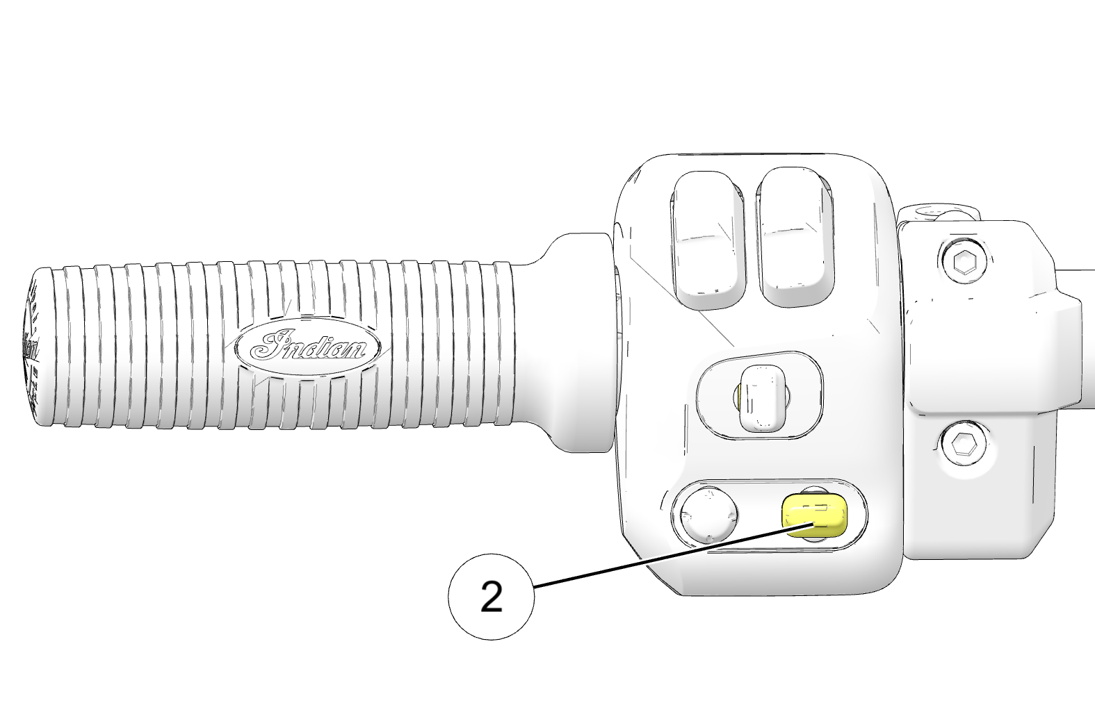
3.3.7.3.2: Select Switch
Use the 3–way select switch 2 to do the following:
Press up and down to navigate display screen.
Press center to select.
Long press to drop down settings panel.
3.3.7.3.3: Trigger Switches
There are trigger switches located on the reverse side of both
the right and left 1 switch cubes.
Use the trigger switches to do the following:
Press the right trigger switch to confirm selection.
Press the left trigger switch to back out of menu screens.
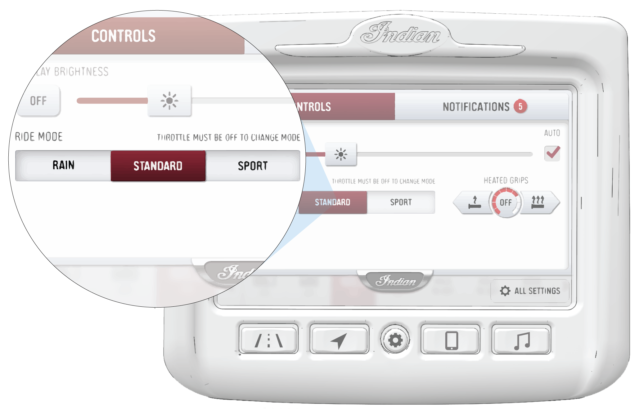
3.3.7.4: Ride Command Ride Modes
You can choose between three ride modes, Rain, Standard, or Sport
for an experience customized to your riding style. The throttle map
for each ride mode was designed with a specific application in mind,
resulting in one motorcycle with three distinct personalities.
NOTICE
For the ride mode to change, the throttle must
be fully disengaged. If you change the ride mode while the throttle
is engaged, a spinning icon will appear indicating that the ride mode
has not yet changed. Once the throttle is disengaged, the icon will
disappear and the ride mode will change.
Rain
Rain mode is ideal for rainy conditions,
or when the road is wet. The throttle response is decreased, maintaining
control and traction.
Standard
Standard mode features a crisp
throttle response and well-balanced power delivery for responsive
passing power and predictable, slow-speed handling.
Sport
Sport mode is designed for situations
when instant response is needed. Sport mode quickens the throttle
response and has a more aggressive power delivery for increased acceleration.
3.3.7.5: Ride Command Settings
From the Settings Menu you can view important details about your
vehicle and personalize your touchscreen display. The settings menu
is comprised of four categories: Information, General, Time, and Vehicle.
General Information
From the Information
settings menu you can view the following:
Vehicle Identification Number (VIN)
Mileage
Installed Software Version
Oil Change Interval
General Settings
From the General settings
menu you can do the following:
Themes (Day/Night/Auto)
Manage Bluetooth® Devices
Change the Language
Set the Speed Units of Measure (MPH or KPH)
Set the Temperature Units (F or C)
Update Software
Update Maps
Clock
From the Time Settings you can do
the following:
Set the Time Format (12 hour or 24 hour)
Enable GPS Time (automatically sets the time to the time zone
you are currently in)
Set Time (if GPS Time is not enabled)
Audio
From the Audio Settings you can adjust
the following:
Fade
Equalizer
Speaker Layout
Automatic Volume Control
Radio Presets
Radio Tuner Region
Vehicle Information
From the Vehicle Settings
you can do the following:
Oil Life/ Service Reset
Access Vehicle Diagnostics
Cylinder Deactivation
GPS Status
3.3.7.6: Fog Light Button
The fog light button can be accessed on the Control
Panel.
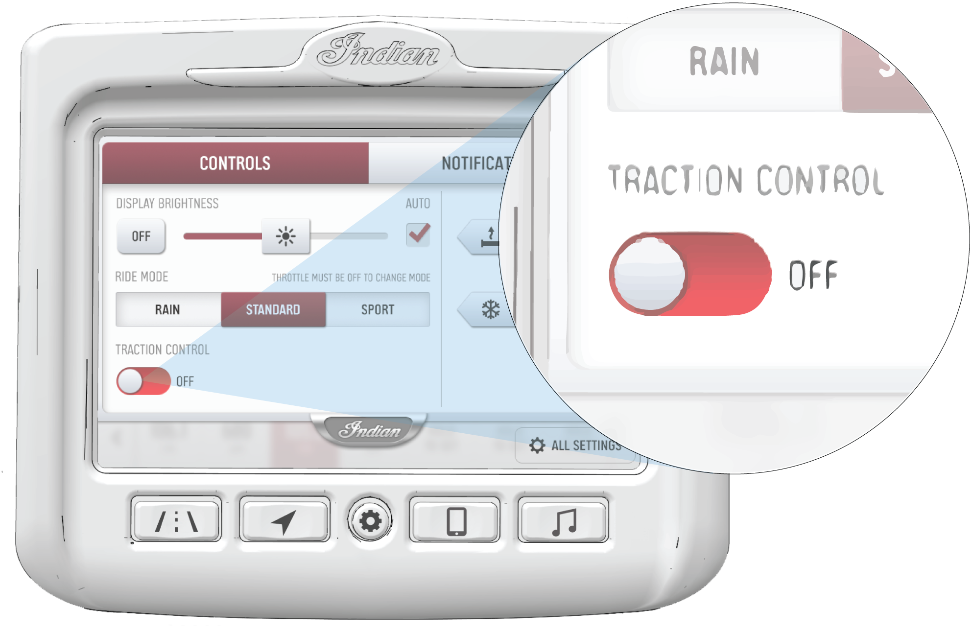
3.3.7.7: Traction Control
To disable the Traction Control, do the following:
Press the Menu/Control button to bring up the Control Panel.
Tap on the Traction Control toggle switch to disable Traction
Control.
A prompt will appear asking you to confirm that you want to
disable the Traction Control. Press DISABLE to confirm.
NOTICE
Traction Control will not become disabled until the
throttle is released.
To re-enable Traction Control, press the Traction Control toggle
switch again.
NOTICE
Traction Control is automatically enabled after
every power cycle of the bike.
3.3.7.8: Electronic Shock Preload (If Equipped)
NOTICE
There are multiple ways to adjust the electronic
shock preload. The process below only details one method.
To adjust the electronic preload (EPL), do the following:
Press the Menu/Control button to bring up the Control Panel.
Tap on the riders button 1 to adjust the weights of
riders.
Tap on the luggage 2 to adjust the weight of the luggage
setting.
Small adjustments can be made using the plus and minus buttons 3 to fine tune the weight settings.
The electronic shock E-Preload feature may require calibration
in the event of an error. Follow the on-screen prompts while
maintaining control of the stationary vehicle. The electronic
shock preload calibration procedure will automatically cycle the shock
to the highest and lowest preload positions.
The calibration can be initiated using the following steps on the
Ride Command display:
Press the Menu/Control button to bring up the Control Panel.
Tap on the All Settings button.
Tap on the Vehicle button.
Tap the Shock Preload button.
Tap the Advanced button.
Tap the Calibrate 3 button.
Follow the on-screen prompts.
3.3.7.10: Edit Weights
To edit rider, passenger, and cargo weights:
Tap on the Vehicle button.
Tap the Shock Preload button.
Tap Edit Weights.
Tap the plus (+) or minus (-) buttons to edit the individual
weights.
The heated grips heat level displays momentarily after changing
the heat level. For models equipped with Ride Command, a brief pop-up
will appear on the touchscreen display when heat level is changed.
To change the heated grips level on the Ride Command display, open
the Control panel and tap to adjust the temperature either up, down,
or off.
The INDIAN MOTORCYCLE Ride Command touchscreen display can be connected
to a smart-phone and a headset simultaneously.
To pair a device, do the following:
From the Bluetooth® Devices settings screen, the Phone
screen, or the Music screen, tap on the Add Device button to bring
up the pairing prompt.
Put your Bluetooth® device into pairing mode.
Select the name of the device you want to pair from the touchscreen
display to finish the pairing process.
Confirm pairing (if applicable). Depending on the device you
are pairing to the display you may be prompted to confirm pairing.
For a list of supported devices please visit https://ridecommand.indianmotorcycle.com/en-us/supported-devices.
3.3.7.14: RIDE COMMAND+
Your vehicle may come equipped with RIDE COMMAND+ technology, which
gives you access to your vehicle’s custom information including
Vehicle Health, Vehicle Locator and Issue Diagnostics (if equipped)
along with a variety of features via the INDIAN MOTORCYCLE mobile
app. You will need a cellular connection to view these features.
To learn more about RIDE COMMAND+,
including equipped or compatible vehicles, specific features, and
to access the RIDE COMMAND+ User Guide, visit ridecommand.indianmotorcycle.com or scan the QR code:
Disclaimer: RIDE COMMAND+ features vary by region.
3.3.7.15: Update Software and Maps
For the latest software and maps for the Ride Command display,
go to: https://ridecommand.indianmotorcycle.com.
The display software and maps can be updated by connecting a USB
stick containing the latest software version to the USB port located
in the right-hand storage compartment. The Update Software menu in
Settings will list any available updates on the USB stick. Choose
the correct version and wait for the update to complete before removing
the USB stick. The touchscreen display will automatically restart
when software is updated.
NOTICE
A USB 2.0 or USB 3.0 flash drive formatted to
exFAT® or FAT32 is required to successfully perform a software
update. The display will not recognize flash drives that do not meet
these requirements.
NOTICE
For map updates, a 32GB or greater USB 2.0 or
USB 3.0 flash drive formatted to exFAT® is required.
IMPORTANT
Do not remove power from the display during
the update process.
3.3.7.16: Over the Air Updates
NOTICE
Over the air updates are only available on models
equipped with a Telematic Control Unit (TCU).
If your model is equipped with a Telematic Control Unit, the motorcycle
will automatically download software updates from the cloud when the
motorcycle is powered on and a cell connection is available. All downloads
occur in the background and can be resumed if the connection is interrupted
or if the motorcycle is turned off.
How to Install Software
Once new software
has been downloaded to your display, you will be prompted with a notification.
To install new software, do the following:
Navigate to the General Settings tab in the Settings menu.
Navigate to the Update Software page.
Press the “Install” button.
NOTICE
The following conditions must be met for the installation to initiate:
the battery voltage must be greater than 12.5 V, the wheel speed must
be 0 mph (0 kph), and the engine must be turned off.
NOTICE
The
display will restart after the installation has successfully completed.
NOTICE
Critical updates will be installed automatically.
A notification will display once the update is compete.
After the update has been completed, release notes will be
provided on the software update screen.
3.3.7.17: USB Port
The USB Port makes it easy to power devices, such as phones, audio
sources, or GPS units, in addition to allowing you to stream music
through the LCD display to your Bluetooth® headset. On models
equipped with a Ride Command display, the USB port is also used to
update the display software. The USB port is located in the right-hand
storage compartment or in the top storage compartment. For the latest
software, go to https://ridecommand.indianmotorcycle.com.
Challenger and Pursuit Models
Chieftain PowerPlus and Roadmaster PowerPlus
Models
IMPORTANT
Due to harsh riding environments, INDIAN
MOTORCYCLE recommends using a USB device with retention features.
3.3.7.18: Apple CarPlay®
Apple CarPlay® seamlessly integrates your iPhone® with
the motorcycle’s Ride Command display and hand controls. Make
phone calls, access your music, send and receive messages, get directions,
and more while you stay focused on the road.
3.3.7.19: Rider Assist Systems (If Equipped)
The Rider Assist Systems, such as Bike Hold Control, Blind Spot
Warning, Tailgate Warning, and rear Collision Warning Lights are designed
to provide the rider with alerts or information of the surrounding
conditions.
The rider must not solely rely on the information from these systems
as certain object shapes, their surfaces, and position may affect
the ability of the radar to detect them with accuracy, which may cause
the rider to receive incorrect information.
NOTICE
Rain, fog, dust, dirt, and frost can degrade
the performance of the radar system and degrade the ability to detect
vehicles. If the blindness of the environment is high enough, the
system may disable itself until the radar visibility clears up.
NOTICE
While cornering or turning, lean angle can reduce
system performance.
3.3.7.19.1: Bike Hold Control
Bike Hold Control assists the rider by engaging the rear brake,
when requested, to prevent the vehicle from rolling backwards or forwards
without the need for the rider to constantly apply the brakes.
The ability for the system to hold the bike stationary may be affected
by loose or slippery surfaces or high slope angles. The rider must
always exercise caution when engaging Bike Hold Control and remain
prepared to take control of the bike.
Avoid engaging Bike Hold Control on non-asphalted surfaces or inclines
greater than 30%.
Symbol
Indicates
Bike Hold Control is available to activate.
Bike Hold Control is actively holding the bike stationary.
This indicator lamp will flash when Bike Hold Control is
about to release or is actively releasing the brakes.
This indicator
lamp will become solid when Bike Hold Control has a fault.
Bike Hold Control will be available to activate when:
the bike is stationary
the engine is running
the sidestand is up
Once all conditions are met, the grey Bike Hold Control symbol
will appear in the upper area of the display screen.
Activate Bike Hold Control by pulling the front lever firmly or
pressing the rear brake lever firmly.
Bike Hold Control will deactivate when:
riding forward by gradually opening the throttle and releasing
the clutch (some initial resistance may be felt until Bike Hold releases)
the front brake lever is pulled firmly with a short pulse
turning the engine off
putting the sidestand down
Maximum hold time is 3 minutes. A popup warning covers the screen
15 seconds before Bike Hold Control gradually releases.
WARNING
Bike Hold Control must not be used as a substitute
for a parking brake. The rider must remain seated and attentive while
Bike Hold Control is active.
NOTICE
An incorrectly adjusted mechanical clutch lever
freeplay can affect Bike Hold Control performance. See the Mechanical
Clutch Lever Freeplay section to ensure the mechanical clutch lever
freeplay is adjusted correctly.
3.3.7.19.2: Blind Spot Warning
When riding, there is an area behind each side of the motorcycle
and rider that is not always visible to the rider even when using
the mirrors. These are referred to as the blind spot zones. Blind
Spot Warning alerts the rider to vehicles in these blind spots zones.
It uses the rear radar to monitor adjacent lanes and activates visual
warnings on the display and mirrors when vehicles enter or are approaching
the blind spot zones. Blind Spot Warning will only be active above
10 mph (16 km/h). A Blind Spot Warning will not appear if the motorcycle
is passing another vehicle faster than 8 mph (13 km/h) relative to
the other vehicle.
Rear View Mirrors—Blind Spot Warning Light
Blind Spot Warning Shown on the Display Screen
Rear Radar Sensor area
WARNING
The Blind Spot Warning is an aid. It does
not replace the need for the rider to be aware of all situations when
riding.
The rider must always maintain a high level of awareness
and concentration while riding, always use the mirrors and check the
blind spots. The rider must not solely rely on the Blind Spot Warnings.
The rider must also look over their shoulder (head check) prior to
overtaking or changing lanes.
The rider is responsible for detecting
all other vehicles, estimating the distance between them and the motorcycle,
and then maneuvering the motorcycle in a safe and responsible way
to avoid any collision.
The rider must also obey all speed limits,
observe all road signs and road markings, and react accordingly to
any environmental influences such as thick fog, heavy rain, etc.
Operating and riding the motorcycle safely and correctly is always
the rider’s sole responsibility.
WARNING
The performance of the rear radar sensor may
be affected by smaller vehicles such as bicycles or motorcycles, or
vehicles with large flat surfaces such as trailers.
Riders may
be warned with a delay, or not at all, due to the time required for
the system to calculate and inform the rider of vehicles approaching
and entering the blind spot zones at higher speeds.
WARNING
The rear radar sensor cover may become covered
by road dirt, mud, rain, ice, snow, etc.
Always make sure to
check and carefully clean the rear radar sensor cover before riding
the motorcycle. Ensure only soapy water and a soft sponge are used
to clean the rear radar sensor cover and avoid using any abrasive
material or chemicals that could damage the cover.
Do not paint
over, attach stickers to, or attach other objects to the rear radar
sensor.
The rear radar sensor’s ability to detect a vehicle
in the rider’s blind spot may be effected and give incorrect
indications. This may lead to a motorcycle accident.
WARNING
Always make sure that no accessories, luggage,
or passenger’s items cover or obscure the rear radar sensor
cover or sensor range.
When riding with a passenger make sure
that their clothing does not overhang the seat and cover the rear
radar sensor cover.
The rear radar sensor’s ability to
detect a vehicle in the rider’s blind spot zone will be affected
if foreign objects enter or cover the rear radar’s field of
view and could send incorrect or missing warnings. This may lead to
a motorcycle accident.
NOTICE
The performance of the rear radar may be affected
by incorrectly set rear suspension preload. Refer to the Shock Preload
Adjustment section to ensure the rear suspension preload is set correctly
for the loading conditions.
Blind Spot Warning Settings
The Blind Spot
Warning system can be enabled and disabled manually by the rider.
The mirror light brightness can be changed in the Blind Spot Warning
settings. The AUTO setting will continuously adjust the mirror light
brightness to account for the ambient light conditions.
There are two levels of warnings when this feature detects
a vehicle.
Level 1 activates when a vehicle moves into or is approaching
the blind spot zone. A warning bar shows on the side of the display
and the mirror light activates on the side the vehicle is located.
Level 2 activates when a vehicle is in or is approaching the
blind spot zone and the rider activates the turn signal on that side
of the bike. The car icon in the display warning bar and the mirror
light flash.
The ON setting allows both Level 1 and Level 2 warnings. The
ONLY DURING TURN SIGNALS setting allows only Level 2 warnings. The
OFF setting disables all warnings. Warnings on the bike display or
on the mirror can be disabled individually.
3.3.7.19.3: Tailgate Warning
Tailgate Warning uses the rear radar to monitor the area behind
the motorcycle and alerts the rider to vehicles that are following
at a close distance. A warning will show on the display when a vehicle
is following too close.
Tailgate Warning will only be active above 18 mph (29 kph).
Close following vehicle warning:
Very close following vehicle warning:
NOTICE
When in a group motorcycle ride, this feature
may frequently detect motorcycles riding at a close distance. Disable
the feature to reduce unwanted warnings.
Less Sensitive
Tailgate warnings will only be shown for very close following
vehicles.
More Sensitive
Tailgate warnings will be shown for close and very close
following vehicles.
Off
Tailgate warnings are disabled for following vehicles.
3.3.7.19.4: Rear Collision Warning Lights
Rear Collision Warning aids in reducing the likelihood of a rear-end
collision by flashing lights to warn other vehicles. This feature
can be disabled on the Rider Assist menu.
North America Models
Rear saddlebag lights flash
INTL Models
Turn signal hazard lights flash
3.3.7.19.5: Electronic Combined Braking
Electronic Combined Braking is a linked braking system controlled
by the ABS module that generates additional stopping power on the
opposing brake system. When the front brake is applied the system
will actuate the rear brakes, and vice-versa, allowing for approximately
25-40% improved stopping efficiency and reduced stopping distance.
3.3.7.19.6: Rider Assist Widget
The Rider Assist Widget shows an icon for each of the following
features. Each feature can be enabled or disabled by clicking on the
feature box on the display.
Tailgate Warning
Blind Spot Warning
Bike Hold Control
Bike Info Screen
The Bike Information Screen
shows an icon for each of the following features. Each feature can
be enabled or disabled by clicking on the feature box on the display.
Tailgate Warning
Blind Spot Warning
Bike Hold Control
3.3.8: Misfire Detection
If a misfire is detected, the check engine indicator lamp will
begin to flash and fuel will be cut to the affected cylinder(s). The
check engine indicator lamp will continue to flash until the ignition
switch has been moved to the off position. Restarting the engine will
clear the flashing indicator and restore fuel to both cylinders. If
another misfire occurs, the check engine indicator lamp will resume
flashing and fuel will once again be cut to the affected cylinder(s).
After the 3rd misfire, P0314 misfire fault is determined
& set, the check engine light will remain on and fuel will be
cut to the affected cylinder(s). If this occurs, your INDIAN MOTORCYCLE
dealer can assist.
3.3.9: Battery Charge Port/Heated Gear Plug
The Battery Charge Port is located on the dash and a maintenance
charger can be connected to it for extended periods (e.g. winter storage).
Challenger and Pursuit Models
Chieftain and Roadmaster Models
CAUTION
Wait until bike cools to ambient temperature
before plugging a battery charger into the battery charge port. Avoid
routing charger cables over hot or sharp surfaces.
3.3.10: Headlights
The headlights automatically come on when the engine is started.
WARNING
Motorcycle riders must remain as visible as possible
at all times. To aid in this, the headlight must be on at all times.
Do not modify the ignition/headlight wiring to circumvent the automatic
headlight feature.
The headlights operate only when the engine is running. You can
use the high/low headlight beam switch to override this function and
allow the headlights to operate when the engine is not running. Turn
the power switch on, then toggle the high/low headlight beam switch
to turn the headlights on.
3.3.11: Throttle Control Grip
The throttle control grip is located on the right handlebar. Use
the throttle control grip to control engine speed.
While seated in the proper riding position:
Roll the grip rearward 1 to open the throttle (increase
engine speed and power).
Roll the grip forward 2 to close the throttle (decrease
engine speed and power), and cancel cruise control.
The control grip is spring loaded. When you release the grip, the
throttle returns to the idle position.
3.3.12: Clutch Lever
The clutch lever 1 is located on the left handlebar. Disengage
the clutch before shifting gears. For smooth clutch operation, pull
the lever quickly and release it in a brisk but controlled manner.
To disengage the clutch, pull the lever toward the handlebar.
To engage the clutch, release the lever in a brisk but controlled
manner.
3.3.13: Gear Shift Lever
The gear shift lever is located on the left side of the motorcycle.
Operate the lever with your foot.
Press downward on the toe lever to shift to a lower gear.
Lift upward on the toe lever to shift to a higher gear.
On models equipped with a Tire Pressure Monitoring
System (TPMS), the sensors are located 180° from the valve stem.
Use caution when servicing tires. To avoid damaging a sensor, break
the bead at the valve stem, then at 90° and 270° from the
valve stem as required.
On models equipped with TPMS, the pressure of each tire can be
viewed on the Ride Command display. If dashes display instead of a
pressure value while traveling above 15 mph (24 kph), the system may not be functioning
properly. See your dealer for service.
The TPMS warning indicator will illuminate if low tire pressure
is detected. Always correct low tire pressure promptly. Always inspect
tire pressure and condition before each ride. See the Tire Pressure
section for more information.
The TPMS display may indicate an increase in tire pressure while
riding, a normal occurrence as tires warm up. Riding into colder conditions
may result in a drop in tire pressure as tires cool down. Regardless
of conditions, low tire pressures should always be corrected promptly.
3.3.15: Lower Fairing (If Equipped)
Each side of the lower fairing has levers 1 that allow
the rider to open and close vents in the front of the fairing that
allow air flow to the rider. The air vents are infinitely adjustable
and opening the vents fully may or may not provide optimal cooling
based on the size or position of the rider(s).
3.3.16: Trunk (if equipped)
Do not exceed the cargo capacity of a trunk, a cargo rack or a
trunk/cargo rack combination. The capacity for the trunk alone, as
well as for any trunk/cargo rack combination, is listed in the table
below. The capacity for a rack alone is 5 lb (2.2 kg). If you load a rack with 5 lb (2.2 kg) of cargo,
do not add more than 25 lb (11.3 kg) to a hard trunk.
Hard Trunk
30 lb (13.6 kg)
Cargo Rack (Alone)
5 lb (2.2 kg)
NOTICE
Before riding, ensure that the trunk latches are
properly secured. Before leaving the vehicle unattended, ensure the
security screws are securely installed.
12-Volt RCA Power Plug
The RCA power plug
(with cover) mounts to the switch panel and is plugged into the main
vehicle wire harness.
3.3.17: Hard Trunk Removal (If Equipped)
If applicable, remove the left and right saddlebags (see Saddlebags) and remove the trunk lock
fastener 1 from each trunk latch.
Disconnect the antenna harness plugs 2 and trunk
harness multi-plug 3.
NOTE
The harness connectors
are located above the metal mounting plate 4.
Lift the trunk latches 5 to unlock the trunk from
the mount.
Lift up on the rear of the trunk 6 and slide rearward 7 to release the trunk from the motorcycle.
Carefully gather the wiring harness and place in seat storage
compartment.
Place the cover over the compartment to close the compartment.
If your model is equipped with a passenger floorboard, the passenger
floorboard is adjustable for both height and angle.
To adjust:
Position the passenger floorboard vertically for fastener access.
Remove the fasteners 2.
Reassemble the floorboard to the desired height 1, 2, or 3.
NOTE
Adjust the floorboard angle in the
fastener pivot slots 4 to the desired angle position prior
to retightening.
TORQUE
19 ft-lbs (25 N·m)
3.3.19: Saddlebags
NOTICE
The left saddlebag removal procedure is similar
to the right saddlebag. The right saddlebag is shown in the illustrations.
Do not exceed the weight limit of each saddlebag. Always distribute
weight evenly in each of the saddlebags. Refer to the saddlebag/cargo
warning label on or near the saddlebag for cargo capacity.
Hard bag capacity is 22 lb (10 kg) of cargo per side.
Hard Bag Removal
Remove the side cover.
Unlock the electric saddlebag locks (if equipped).
NOTICE
The provided key can also be used in the saddlebag latch
buttons to unlock the saddlebag lids.
Disconnect the saddlebag lock wiring near the seat 1.
Press the lid latch release button and lift the lid.
Remove the saddlebag fastener bolts 2.
Tilt the saddlebag away from the frame of the vehicle to remove
it.
To reinstall, place the hard bag in a fully seated position
on the muffler.
Insert saddlebag fastener bolts and torque to specification.
TORQUE
Fastener Bolts:
18 ft-lbs (24 N·m)
Reconnect the electrical wiring.
Reinstall the side panel, using care to avoid damaging electrical
wires.
WARNING
Improper saddlebag installation can
result in loss of control, accident and driving hazards for other
motorists (if saddlebag falls from the motorcycle). Always make sure
saddlebags are mounted properly.
3.3.20: Saddlebag Closure
Close lid. Make sure lid is aligned with bin.
Press firmly on lid until latch is fully engaged and lid is
closed tightly.
NOTICE
Make sure saddlebag latch is secure after closing
lid.
3.3.21: Sidestand
The sidestand is equipped with a safety switch that prevents operation
of the motorcycle if the sidestand is deployed.
WARNING
An improperly retracted sidestand could contact
the ground and cause a loss of control resulting in serious injury
or death. Always retract the sidestand fully before operating the
motorcycle.
To park the motorcycle, swing the end of the sidestand downward
and away from the motorcycle until it is fully extended. Always turn
the handlebars to the left for maximum stability. Lean the motorcycle
to the left until the sidestand firmly supports the motorcycle.
CAUTION
If the motorcycle weight is not resting on the
sidestand, it will not lock. In this situation, any movement of the
motorcycle could cause the sidestand to retract slightly. If the sidestand
is not in the full forward position when the motorcycle weight is
rested on it, the motorcycle could fall over, possibly causing injury
and damage to the motorcycle.
To retract the sidestand, straddle the motorcycle and bring it
to the fully upright position. Swing the end of the sidestand upward
and toward the motorcycle until it is fully retracted.
3.3.22: Windshield
3.3.22.1: Windshield Removal
Power the windshield to full up position to gain access to
the five screws securing the windshield.
Remove the five screws securing the windshield 1.
Pull the windshield forward and away from the vehicle.
Reverse this procedure to reinstall the windshield.
TORQUE
Windshield Screws:
36 in-lbs (4 N·m)
3.3.22.2: Windshield Care
Clean the windshield with a soft cloth and plenty of warm water.
Dry with a soft clean cloth. Remove minor scratches with a high-quality
polishing compound designed for use on polycarbonate surfaces.
NOTICE
Brake fluid and alcohol will permanently damage
the windshield and the adjustable wind deflectors. Do not use glass
cleaners, water or soil repellents, and petroleum or alcohol based
cleaners on the windshield or the adjustable wind deflectors, as these
products can damage these parts.
3.3.23: Mirrors
Your vehicle is equipped with convex mirrors. Objects seen in a
mirror may be closer than they appear. Always adjust mirrors before
riding.
To adjust the mirrors, sit on the motorcycle in the anticipated
riding position. Adjust the mirrors so that you can see a small portion
of your shoulders in each mirror.
3.3.24: Brakes
The front brake lever activates the front brake calipers. The rear
brake pedal activates the rear brake caliper. On models equipped with
Electronic Combined Braking, both the front and rear brake systems
will activate when using the front brake lever or rear brake pedal.
For maximum brake effectiveness, apply the front brake lever and the
rear brake pedal together.
3.3.24.1: Anti-Lock Brake System (ABS)
The anti-lock brake system automatically adjusts brake pressure
as needed to provide optimum braking control, reducing the chance
of wheel lock-up during hard braking events or when braking on rough,
uneven, slippery or loose surfaces. See Anti-Lock Brake System Response.
The anti-lock brake system cannot be turned off.
The ABS indicator always flashes when vehicle power is turned
on. It remains illuminated until the anti-lock system activates, which
occurs when vehicle speed exceeds 3 mph (5 kph). If the ABS light does not come
on, your authorized INDIAN MOTORCYCLE dealer can assist.
When the lamp is flashing, the anti-lock brakes will not activate,
but the conventional brake system will continue to operate normally.
When the anti-lock brakes engage during a braking event, the
rider will feel pulsing at the brake levers. Continue to apply
steady pressure to the brakes for the best stopping performance.
If the lamp continues to flash after vehicle speed exceeds 3 mph (5 kph), the
ABS system is not functioning. See your INDIAN MOTORCYCLE dealer or
other dealer promptly for service.
Operating with non-recommended tires or improper tire pressure
may reduce the effectiveness of the anti-lock brake system. Always
use the recommended size and type of tires specified for your vehicle.
Always maintain the recommended tire pressure.
The anti-lock brake system will not prevent wheel lockup, loss
of traction or loss of control under all conditions. Always
adhere to all safe motorcycle-riding practices as recommended.
It is not unusual to leave tire marks on the road surface during
a hard braking event.
The anti-lock brake system does not compensate for or reduce
the risks associated with:
excessive speed
reduced traction on rough, uneven or loose surfaces
poor judgment
improper operation
3.3.24.2: Front Brake Lever
The front brake lever is located on the right handlebar. This lever
controls only the front brakes on models not equipped with Electronic
Combined Braking and activates both the front and rear brake systems
on models equipped with Electronic Combined Braking. The front brakes
should be applied simultaneously with the rear brakes. On models equipped
with Electronic Combined Braking it is normal to feel some minor pulsations
in the lever when both front and rear controls are activated simultaneously.
To apply the front brake lever, pull the lever toward the handlebar.
See Braking for braking
procedures.
The front brake lever reach (distance to the hand grip) is adjustable.
To adjust the front brake lever reach, do the following:
Gently push and hold the lever away from the hand grip.
The adjuster wheel 1 is located on top of the lever.
To increase reach distance, rotate the adjuster to a lower
number.
To decrease the reach distance, rotate the adjuster to a higher
number.
3.3.24.3: Rear Brake Pedal
The rear brake pedal 1 is located on the right side of
the motorcycle. Press downward on the rear brake pedal to apply the
rear brake on models not equipped with Electronic Combined Braking
and to apply both the front and rear brake systems on models equipped
with Electronic Combined Braking. On models equipped with Electronic
Combined Braking it is normal to feel some minor pulsations in the
pedal when both front and rear controls are activated simultaneously.
See the Rider Assist System section for more information about
the Electronic Combined Braking system.
WARNING
Resting your foot on the brake pedal will cause
excessive and premature wear of brake pads and reduced braking efficiency,
which could result in serious injury or death.
To close, press fuel cap downward until it clicks.
Manual Override
NOTICE
The manual
override process should only be used in case of system lock issues
or loss of bike electric power. You should use the electric unlock
process detailed on Fuel Cap, or have a authorize dealer repair the system if it does not work.
The manual override process shows you how to perform a 1 time manual
reset of the cap lock to add fuel if stranded.
Ensure engine is not running before attempting to manually
unlock fuel cap
NOTICE
Cap will automatically lock/re-lock
if closed and engine is running.
Remove the console by unscrewing fastener at back of console 1.
With fastener removed, lift the rear of console enough to clear
fuel cap and push forward to release front mount from keyway.
Lift console up and out, away from the fuel tank, to complete
removal.
Use a small, narrow tool to push the lock solenoid at the front
of fuel cap (under the latch) to the left position 2.
Reinstall console.
NOTICE
Console cannot be
re-installed with fuel cap open. It is recommended that the console
be re-installed prior to opening the fuel cap.
Release cap via latch per normal operation.
Chapter 4: Pre-Ride Inspections
4.4.1: Overview
To keep your motorcycle in safe operating condition, always perform
the recommended pre-ride inspections before each ride. This is especially
important before making a long trip and when removing the motorcycle
from storage.
Challenger and Pursuit Models
Chieftain and Roadmaster Models
WARNING
Failure to perform the recommended pre-ride inspections
could result in component failure while riding, which could result
in serious injury or death. Always perform the pre-ride inspections
before each ride. When inspection reveals the need for adjustment,
replacement or repair, perform the service promptly, or your authorized
INDIAN MOTORCYCLE can assist.
WARNING
Read the entire Instruments, Features and Controls
section of this manual before riding your motorcycle. A complete understanding
of the features and capabilities of your motorcycle is essential to
its safe operation. Anything less may result in serious injury or
death.
You must be familiar with all instruments and controls to perform
the pre-ride inspections.
NOTICE
During the pre-ride inspections you may use products
that are potentially hazardous, such as oil or brake fluid. When using
any of these products, always follow the instructions and warnings
on the product packaging.
When inspections reveal the need for adjustment, replacement or
repair:
or see your authorized INDIAN MOTORCYCLE dealer or other qualified
dealer
4.4.1.1: Electrical Inspections
Turn the power switch on and move the stop/run switch to RUN before
performing the following electrical inspections. Turn the power switch
off after completing these inspections. If inspection of any electrical
item reveals component failure, repair or replace the component before
operating the motorcycle.
Item
Inspection Procedure
Headlamp
Move the headlight switch from low beam to high beam to turn
the lights on and verify operation of both beams. Start the engine.
Switch to high beam. Verify that the high beam indicator comes on
and that lamp brightness increases. Press and hold the low beam switch
to verify “Flash to Pass” functionality.
Taillights/Brakelight
Verify that the taillights and license plate light illuminate.
Verify that the taillight lamps increase in brightness when the front
brake lever is applied and also when the rear brake pedal is applied.
Turn Signals
Move the turn signal switch to the left. Verify that front
and rear left turn signals flash, as well as the corresponding light
on the indicator panel. Move the switch to the center position and
push it inward to cancel the signal. Verify that the signals and the
indicator light stop flashing. Repeat the procedure for the right
turn signals.
Saddlebags
Press the lock button. Verify that the compartments are locked.
Press the unlock button. Verify that the compartments are unlocked.
Trunk (if equipped)
Verify routings under trunk are properly secured and not touching
the rear fender.
Emergency Flashers
Press and hold the turn signal switch in for 1 second to activate
flashers. Verify that all four turn signals flash, as well as the
lamps on the indicator panel. Turn the flashers off. Verify that all
signals and indicator lamps stop flashing.
Horn
Press the horn switch. Verify that the horn sounds loudly.
Neutral Indicator
Place the transmission in neutral. Verify that the neutral
indicator lamp illuminates and that the letter "N" displays in the
gear position display.
Low Oil Pressure Display
Start the engine. Verify that the low oil pressure indicator
is not illuminated.
Engine Stop/Run Switch
Start the engine. Move the stop/run switch to the STOP position.
Verify that the engine stops.
Rear Radar Sensor Cover
Ensure that the Rear Radar Sensor Cover is clear of debris.
Verify smooth operation, inspect pivot bolt and spring.
Fasteners
Inspect for loose, damaged or missing fasteners.
Mirrors
Adjust for proper rear view.
Trunk/Saddlebags
If equipped, make sure the trunk and saddlebags are properly
installed and that lids are securely closed.
4.4.2: Engine Oil Level
With the semi-dry sump lubrication system, the engine oil level
on the dipstick will fluctuate, depending on the motorcycle’s
position and engine temperature when checked. To ensure a proper reading
of the engine oil level, follow all inspection procedures closely.
WARNING
Operating with insufficient, deteriorated or
contaminated engine oil will cause accelerated wear and may result
in engine or transmission seizure, which could result in loss of control
and serious injury or death. Check the oil level frequently.
Always check the oil after running a cold engine at idle for 30
seconds. The oil fill/dipstick is located on the left side of the
motorcycle. Always use the recommended oil. See Engine Oil Recommendation.
Position the motorcycle on level ground in the fully upright
and centered position.
Start the engine (from cold) and allow it to idle for 30 seconds.
Stop the engine.
Remove the dipstick 1 and wipe it clean.
Thread the dipstick until fully seated.
Remove the dipstick and view the oil level.
NOTICE
Do not overfill. Overfilling can result in loss of engine
performance and an oil-saturated air filter. Use a suction device
to remove excess oil if overfilled.
Add the recommended oil as needed to bring the level within
the safe operating range (anywhere between the two marks on the dipstick).
If the oil level on the dipstick is anywhere in the safe range, do
not add oil. Oil should be added only if the proper oil check procedure
is followed and the level is below safe mark.
NOTICE
Oil should be added only if the proper oil check procedure is followed
and the level is below the safe mark.
NOTICE
The
approximate volume between the FULL 2 and ADD 3 marks
on the dipstick is 0.5 qt (0.47 l).
Reinstall the dipstick securely.
Repeat steps 3–7 to ensure the level is within the safe
operating range.
4.4.3: Tires
WARNING
Operating the motorcycle with incorrect tires,
incorrect tire pressure or excessively worn tires could cause loss
of control or accident. Under inflation can cause a tire to overheat
and result in a tire failure. Only use tires approved by INDIAN MOTORCYCLE
for the model of the motorcycle. See your dealer for more information.
Use of unapproved or an improperly mixed front and rear tire can result
in decreased handling performance and stability, potentially leading
to reduced control of the motorcycle. Always maintain proper tire
pressure as recommended in the rider’s manual and on safety
labels.
4.4.3.1: Tire Pressure
Improper tire pressure can result in irregular tire wear, tire
failure, reduced fuel economy and a poor riding experience. It can
also affect handling and stopping ability.
Slow tire pressure loss over time is normal for a functional tire.
Although a tire pressure monitoring system (TPMS) will alert the user
to a low pressure condition (if equipped), always inspect tire pressure
and condition before each ride.
Check tire pressure before riding, when the tires are cold. This
will provide the most accurate reading, as riding warms the tires
and increases tire air pressure. Tires remain warm for at least 3
hours after a ride. Do not adjust tire pressure immediately after
riding. As tires cool, the pressure will drop and result in underinflation.
Always check and adjust tire pressure when tires are cold.
Using supplied air pressure gauge, adjust tire pressure to the
recommended pressure. See Tire Pressure Chart.
4.4.3.2: Tire Condition
Inspect the tire sidewalls, road contact surface and tread base.
If inspection reveals cuts, punctures, cracks or other wear or damage,
replace the tire before riding. Only use tires approved by INDIAN
MOTORCYCLE for the model of the motorcycle. See your dealer for more
information. Use of unapproved or an improperly mixed front and rear
tire can result in decreased handling performance and stability, potentially
leading to reduced control of the motorcycle.
4.4.3.3: Tire Tread Depth
Replace any tire with a tread depth of less than 1/16 in (1.6 mm).
Tread wear indicators are located in at least six places on the
tread circumference and become visible at a tread depth of approximately 1/16 in (1.6 mm). The
tread wear indicators appear as a solid band across the tread.
You may also use a depth gauge or an accurate ruler to measure
the depth of the center tire tread on both front and rear tires.
4.4.4: Front Brake Fluid Level
Bring the motorcycle to the fully upright position. Position
the handlebars so that the fluid reservoir is level.
View the fluid level through the sight glass 1. The
fluid should be clear. Replace cloudy or contaminated fluid.
The fluid level should be above the minimum indicator mark 2 near the sight glass.
If the fluid level is low, inspect brake pads as outlined on Brake Pads. If pads are not worn beyond
the service limit, inspect the brake system for leaks. Check for signs
of brake fluid leaks around hoses, fittings, reservoir, and brake
calipers.
Pull the front brake lever toward the handlebar and hold it.
The lever should move freely and smoothly. The lever should feel firm
and continue to feel firm until released.
Release the lever. It should return to its rest position quickly
when released.
If the front brake lever fails to perform as stated, service
the brake lever before riding.
4.4.6: Rear Brake Pedal
Press downward on the rear brake pedal. It should move freely
and smoothly. The pedal should feel firm and continue to feel firm
until released.
Release the pedal. It should return to its rest position quickly
when released.
If the rear brake pedal fails to perform as stated or travels
too far before beginning to engage the brake, service the brakes before
riding.
4.4.7: Rear Brake Fluid Level
The rear brake fluid reservoir is located near the rear brake pedal.
View the reservoir level from the right side of the vehicle.
Position the motorcycle on level ground in the fully upright
position.
View the brake fluid through the reservoir sight glass 1.
The fluid should be clear. Replace cloudy or contaminated fluid.
The fluid level should be above the minimum indicator mark 2 on the reservoir body. Add brake fluid as needed.
4.4.8: Brake Lines
Inspect all brake hoses and connections for dampness or stains
from leaking or dried fluid. Tighten any leaking connections to the
proper torque values and replace components as necessary. See the INDIAN MOTORCYCLE Service Manual or an authorized INDIAN MOTORCYCLE
dealer or other qualified dealer.
WARNING
Brake fluid leaks or low brake fluid levels could
cause brake system failure, which could result in serious injury or
death. Do not operate the vehicle with low brake fluid levels or when
leaks are evident (dampness or stains from dried fluid). See your
authorized INDIAN MOTORCYCLE dealer or other qualified dealer.
4.4.9: Throttle
Rotate the throttle control grip. It should rotate smoothly from
the rest position to the completely open position. It should return
to the rest position quickly when released.
4.4.10: Mechanical Clutch
Squeeze the clutch lever 1 toward the handlebar and
release it. It should move freely and smoothly, and it should return
to the rest position quickly when released. If the lever fails to
perform as stated, service the clutch lever before riding.
Freeplay (gap) is the amount of lever movement from the rest
position to the point of cable resistance. Clutch lever freeplay 2 should be 0.5-1.5 mm. Measure the gap between the clutch lever
and the lever housing. Adjust clutch lever freeplay if necessary.
NOTICE
The starter interlock switch is dependent on
the clutch lever freeplay being set correctly to ensure activation
of the clutch safety switch.
4.4.11: Side-stand
On level ground, straddle the motorcycle and bring it to the
fully upright position.
Move the side-stand up to the stored position and down to the
fully extended position several times. It should move smoothly and
quietly. Make sure the return spring holds the side-stand tightly
in place when the side-stand is in the stored position. Adjust or
replace a loose spring.
Inspect the side-stand pivot bolt for looseness or wear. Tighten
or replace a loose or worn bolt.
Periodically test the side-stand safety switch for proper operation.
With the transmission in gear and brakes applied, attempt to start
the engine while the side-stand is down. The engine should NEVER start
in any gear except neutral if the side-stand is down. If the engine
starts during this test, see your dealer for service.
4.4.12: Fasteners
Inspect the entire motorcycle chassis and engine for loose,
damaged or missing fasteners.
Tighten loose fasteners to the proper torque. See the INDIAN
MOTORCYCLE Service Manual or an authorized INDIAN MOTORCYCLE dealer
or other qualified dealer.
NOTICE
Always replace stripped,
damaged or broken fasteners before riding. Use genuine INDIAN MOTORCYCLE
fasteners of equal size and strength.
On level ground, straddle the motorcycle and bring it to the
fully upright position. Turn the handlebars from stop to stop. The
action should be smooth, but not loose.
Make sure wires, hoses and control cables do not interfere
with smooth steering.
4.4.15: Rear Suspension
Check the rear shock absorber mounting and inspect for leaks. See
your dealer for service if you discover leaks or malfunction of any
kind. See Shock Preload Adjustment.
WARNING
Inadequate ground clearance could result in components
contacting the ground, causing loss of control and serious injury
or death. Always ensure ground clearance is at specification.
The
drive belt system must be cool, clean and dry to accurately measure
belt tension (deflection). Do not measure belt tension when the belt
or drive system is wet or when it is hot (such as immediately after
riding).
Check the drive belt for debris.
Inspect drive belt condition. See Rear Drive Belt Condition. If you discover cracks,
broken teeth or frayed edges, replace the drive belt before riding.
See the INDIAN MOTORCYCLE Service Manual or an authorized INDIAN
MOTORCYCLE dealer can assist.
4.4.17: Fuel Level
For the most accurate reading, sit on the motorcycle and bring
it to the upright position before turning it on.
The segments of the fuel gauge show the level of fuel in the fuel
tank. When the last segment clears, a low fuel warning is activated.
All segments including the fuel icon will flash. Refuel promptly.
Chapter 5: Operation
5.5.1: Overview
The operation section of this manual describes how to ensure maximum
performance and longevity through the proper care and operation of
your motorcycle.
Important areas covered by the operation section include:
Engine Break-In
Fueling
Starting the Engine
Shifting Gears
Using Cruise Control (if equipped)
Accelerating
Braking
Stopping the Engine
Parking
NOTICE
Even if you’re an experienced motorcycle
operator or passenger, read all of the safety information in this
manual before operating the motorcycle. See Safe Riding Practices.
5.5.2: Engine Break-In
The engine break-in period for your motorcycle is the first 500 mi (800 km) of
operation. During this break-in period, critical engine parts require
special wear-in procedures so they seat and mate properly. Read, understand
and follow all break-in procedures to ensure the long-term performance
and durability of your engine.
NOTICE
Failure to properly follow the engine break-in
procedures outlined in this manual can result in serious damage to
the engine. Avoid full throttle operation and other conditions that
may place an excessive load on the engine during the break-in period.
The more cautiously you treat your motorcycle during the break-in
period, the more satisfied you will be with its performance later
on. Overloading the engine at low RPM and/or running the engine prematurely
at high RPM may result in damage to the pistons and/or other engine
components.
Observe the following precautions during the break-in period:
Upon initial start-up, do not allow the engine to idle for
long periods as overheating can occur.
Avoid fast starts with wide open throttle. Drive slowly until
the engine warms up.
Avoid running the engine at extremely low RPM in higher gears
(lugging the engine).
Drive within the recommended operating speeds and gears.
5.5.3: Operating Speeds and Gears
Odometer
Break-in Procedure
Miles
Km
0-90
0-145
Do not operate for extended periods above 1/3 throttle or at
any one throttle position. Vary engine speed frequently.
91-300
146-483
Do not operate for extended periods above 1/2 throttle or at
any one throttle position. Vary engine speed frequently.
301-500
484-800
Do not operate for extended periods above 3/4 throttle.
At 500
At 800
Perform the break-in maintenance outlined in the maintenance
section of this manual. Break-in maintenance should be performed by
a dealership. Break-in maintenance must include inspection, adjustments,
fastener tightening and an engine oil and filter change. Performing
break-in maintenance at the required odometer reading helps ensure
peak engine performance, minimal exhaust emissions and maximum service
life of the engine.
5.5.4: Fueling
Always dismount the motorcycle and refuel on level ground with
the sidestand down. Review the fuel warnings. Use only the recommended
fuel. See Fuel Recommendation. Hold the nozzle while filling. Do not rest the weight of the nozzle
and hose on the filler neck. Do not leave the nozzle unattended.
WARNING
Overflows or spilled gasoline could contact a
hot engine or exhaust system and cause a fire, which could result
in serious injury or death. Do not allow gasoline to contact hot components.
WARNING
Always fill the fuel tank slowly to prevent spillage.
Do not overfill the fuel tank. Leave space in the tank to allow for
the fuel to expand.
NOTICE
Fuel can damage painted surfaces and plastic parts.
If gasoline spills on the any part of the motorcycle, immediately
rinse it off with water or wipe it dry with a clean cloth.
Press the center of the fuel cap unlock button located on the
lower right fairing 1.
Challenger and Pursuit Models
Chieftain PowerPlus and Roadmaster PowerPlus Models
Press the fuel cap release button 2 to access the
fuel tank.
Insert the fuel nozzle into the fuel tank filler neck.
Add fuel to the tank until it crests the circular-shaped opening
at the bottom of the filler neck column. The tank is full at this
level. Do not overfill the fuel tank. Fuel level should not rise
into the fill neck. Overfilling may result in degraded performance
of engine and evaporative emissions control system.
Always securely close the fuel cap before remounting the motorcycle.
5.5.5: Priming the Fuel System
If the motorcycle runs out of fuel, prime the fuel system before
attempting to restart the engine.
Fill the fuel tank.
Turn the power switch on.
Move the engine stop/run switch to the RUN position.
Allow the fuel pump to run until it stops (about 2 seconds).
Move the engine stop/run switch to the STOP position.
Repeat steps 3–5 five times.
Move the engine stop/run switch to the RUN position.
The starter interlock system allows the engine to be started only
when the transmission is in neutral, or when the transmission is in
gear with the clutch disengaged (clutch lever pulled in). The engine
should NEVER start in any gear except neutral if the sidestand is
down. See Sidestand.
NOTICE
If the motorcycle runs out of fuel, prime the
system before attempting to restart the engine.
Perform the Pre-Ride Inspections. See Overview. Properly secure any cargo.
Straddle the motorcycle and bring it to the fully upright position.
Retract the sidestand.
NOTICE
When the electrical
system is activated with either the power switch or the starter switch,
the key fob must be within range.
Move the engine stop/run switch to the RUN position.
Shift the transmission to neutral.
Apply the front brakes. Disengage the clutch (pull the clutch
lever fully toward the handlebar).
The motorcycle may be electrically activated by pressing the
power switch. Then with the throttle closed, press and release the
starter switch to start the engine. The starter motor will crank until
the engine starts, but no more than 3 seconds. If the engine does
not start, wait five seconds and try again.
If starting a COOL engine,DO NOT open
the throttle while starting. Idle speed is computer controlled and
idle speed will adjust automatically depending on engine temperature
and air temperature. Allow the engine to warm up for one minute minimum
at low RPM after starting. Do not run the engine above 2500 RPM. If starting a WARM engine,DO NOT open the throttle
while starting.
If either the check engine indicator or the low oil pressure
indicator (or display) remains on after the engine starts, stop the
engine immediately. Refer to the low oil pressure indicator/display
information on Indicator Lamps.
CAUTION
Operating an engine with a misfire or non-firing
cylinder can overheat the catalytic converter, which could result
in catalytic converter damage and loss of emission control. DO NOT
OPERATE the motorcycle if a misfire or non-firing cylinder exists.
See Misfire Detection.
Leave the throttle closed and allow the engine to idle. Idle
speed will gradually slow to normal as the engine warms to operating
temperature.
NOTICE
Do not rev the engine or put the
transmission in gear immediately after starting the engine. Allow
the engine to idle for about 30 seconds after a warm start or at least
one minute after a cold start (longer in cold weather). This will
allow oil to reach all areas before the engine is put under load.
5.5.7: Cold Weather Operation
WARNING
Avoid operating in icy or snowy conditions. Use
caution when driving in temperatures at or below 40 f (4 c). Leave more room to stop,
reduce cornering speeds, and accelerate gradually. Failure to do so
could result in serious injury or death.
When operating in cold weather at or below 40 f (4 c), be advised that:
The grip on your standard vehicle tires will lessen and reduce
traction.
The dense air from the lower temperatures will allow your vehicle
engine to generate more power.
The engine control program and transmission control program
may compensate for lower temperatures and as a result exhibit unexpected
behaviors.
Salt and sand on roadways may reduce the grip on standard vehicle
tires and damage the finish on your vehicle. If you must drive on
salted/sanded pavement, INDIAN MOTORCYCLE recommends washing frequently
and thoroughly to remove any accumulation on your vehicle.
5.5.8: Shifting Gears
WARNING
Forced shifting (without clutch lever pulled
in) could cause damage to the engine, transmission and drive train.
Such damage could cause loss of control, which could result in serious
injury or death. Always pull the clutch lever fully toward the handlebars
to disengage the clutch before shifting gears.
This motorcycle is equipped with a six-speed transmission. Neutral
is located between first and second gear.
Press downward on the toe lever to shift to a lower gear. Lift
upward on the toe lever to shift to a higher gear. Release the clutch
lever after each gear shift.
Shifting to neutral is easiest if the motorcycle is rolling slowly.
To shift from first gear to neutral, gently lift the toe lever a half
stroke.
NOTICE
The transmission is in neutral if you can move
the motorcycle forward or rearward freely without disengaging the
clutch. If the power switch is ON, the neutral indicator illuminates
when the transmission is in neutral.
5.5.8.1: Shifting Gears While Stationary
To locate neutral when the motorcycle is stationary, use
one of the following techniques to load and unload the transmission:
With the clutch disengaged (lever pulled inward), shift into
neutral while rocking the motorcycle forward and rearward.
With the transmission in first gear, gently release the clutch
until it just begins to engage. Apply upward pressure on the toe lever
and quickly pull the clutch inward.
NOTICE
There is a Neutral indicator light on the instrument
cluster.
With the engine at idle speed, apply the front brakes.
Disengage the clutch (pull the clutch lever fully toward the
handlebar).
Push the toe lever downward until you feel it stop in first
gear.
Release the brake lever.
Simultaneously release the clutch lever while opening the throttle
(rolling the throttle control grip rearward) in one smooth motion.
As the clutch begins to engage, the motorcycle will move forward.
To shift to a higher gear, accelerate smoothly to the recommended
shift point. See Recommended Shift Points chart on Recommended Shift Points. With a quick
motion, simultaneously close the throttle completely and disengage
the clutch. Raise the toe shift lever until you feel it stop at the
next gear. Simultaneously release the clutch lever and open the throttle
in one smooth motion.
NOTICE
Within the recommended
speed ranges (see Recommended Shift Points chart on Recommended Shift Points), you can downshift to slow
the motorcycle or to increase power. You may want to downshift when
climbing a hill or passing. Downshifting also helps to decrease speed
when combined with closing the throttle.
To shift to a lower gear (downshift), simultaneously pull the
clutch lever toward the handlebar and close the throttle. Move the
toe shift lever downward until you feel it stop at the next gear.
Simultaneously release the clutch lever while opening the throttle.
WARNING
Downshifting improperly could cause transmission
damage, loss of traction and loss of control, which could result in
serious injury or death.
Reduce speed before downshifting. Always downshift within the
recommended shift points.
Use extreme caution when downshifting on wet, slippery or other
low traction surfaces. Release the clutch lever very gradually in
these conditions.
Avoid downshifting in a curve. Downshift before entering the
curve.
5.5.8.3: Recommended Shift Points
Upshifting (Accelerating)
Gear Change
Recommended Speed
1 to 2
15 mph (24 kph)
2 to 3
25 mph (40 kph)
3 to 4
35 mph (56 kph)
4 to 5
45 mph (72 kph)
5 to 6
50 mph (80 kph)
Downshifting (Decelerating)
Gear Change
Recommended Speed
6 to 5
40 mph (64 kph)
5 to 4
35 mph (56 kph)
4 to 3
25 mph (40 kph)
3 to 2
15 mph (24 kph)
2 to 1
10 mph (16 kph)
5.5.9: Braking
Always allow sufficient stopping distance so that brakes can be
applied gradually.
NOTICE
Applying slightly more front brake than rear brake
generally provides the best braking performance.
To slow the motorcycle with the brakes, close the throttle
and apply both the front and rear brakes gradually.
NOTICE
If the anti-lock brakes engage during a braking event,
the rider will feel pulsing at the brake levers. Continue to apply
steady pressure to the brakes for the best stopping performance.
As the motorcycle slows, disengage the clutch, or downshift
each time vehicle speed reaches a downshift point.
WARNING
Braking improperly could result in loss of control,
which could result in serious injury or death. Avoid braking abruptly.
Always apply the brakes gradually, especially on wet, slippery or
other low traction surfaces. Avoid braking in a curve or turn. Bring
the motorcycle to the upright position before applying the brakes.
5.5.10: Accelerating
Accelerate by opening the throttle (rolling the throttle control
grip rearward). For even acceleration, open the throttle with a smooth,
continuous motion. When you reach the recommended speed for upshifting,
shift up one gear.
WARNING
Accelerating abruptly could cause your body to
shift rearward suddenly, which could result in loss of control. Accelerating
abruptly could also cause loss of control on low traction surfaces.
Loss of control could result in serious injury or death. Always accelerate
gradually, especially on wet, slippery or other low traction surfaces.
5.5.11: Stopping the Engine
Before stopping the engine, bring the motorcycle to a complete
stop. Shift to neutral or disengage the clutch.
WARNING
Stopping the engine with the transmission in
gear while the motorcycle is moving could cause loss of rear wheel
traction or engine and transmission damage, which could cause loss
of control and serious injury or death. Always stop the engine after
the motorcycle is fully stopped and the transmission is in neutral.
If the engine stops unexpectedly while the motorcycle is moving, disengage
the clutch, guide the motorcycle to a safe location off the road and
away from traffic. Turn the power switch off.
Move the engine stop/run switch to the STOP position.
When the engine is fully stopped, turn the power switch off.
5.5.12: Using Cruise Control
The cruise control switches are located on the right handlebar.
Read this section and understand how to safely operate this feature
before using the cruise control.
Cruise control can be activated and adjusted from the right control
using the Cruise Control Switch 1.
Toggle Position
Function
Left
Set/Decelerate
Center
Off/On
Right
Resume/Accelerate
WARNING
Improper operation of cruise control could cause
loss of control and result in serious injury or death. Follow all
cruise operation procedures carefully. Never use cruise control when
roads are wet or slippery. Do not use cruise control when riding in
heavy or congested traffic.
5.5.12.1: Cruise Control Tips
Cruise control can be set in gears 3-6.
Vehicle speed must be above 20 mph (32 kph).
Set speed will vary slightly in hilly terrain.
Cruise control will not resume a pre-set speed if the resulting
acceleration or deceleration rate is too high or too low. For example,
resuming a set speed of 70 mph (113 kph) from 40 mph (64 kph), while in 6th gear, may cause
cruise to disengage.
Cruise control will not engage if brake lights are not operating
properly.
The clutch or either brake must have been activated at least
once since the engine was started for the cruise control to function.
5.5.12.2: Set Speed
Press and release the center of the cruise control switch 1. The amber cruise control indicator will illuminate in the
instrument cluster. Cruise control is enabled, but not set.
Accelerate to the desired speed and press left on the cruise
control switch to activate cruise control. The green cruise control
indicator lamp will illuminate. Cruise control is set to the desired
speed.
5.5.12.3: Resume Speed
After disengaging the cruise control with the brake, throttle or
clutch, press right on the cruise control switch to return to the
set speed.
5.5.12.4: Accelerate
While cruise control is engaged, tap right on the cruise control
switch to increase speed in approximately 1 mph (1–2 kph) increments. Press
and hold the right on the cruise control switch to accelerate to a
new set speed (resets when switch is released).
NOTICE
If you use the throttle to accelerate and then
release it, the cruise control will resume the previously set speed.
5.5.12.5: Decelerate
While cruise control is engaged, tap and release left on the cruise
control switch to decrease speed in approximately 1 mph (1–2 kph) increments. Press and hold left on the cruise control switch to
decelerate to a new set speed (resets when switch is released), or
to the minimum cruise speed of 20 mph (32 kph).
5.5.12.6: Cancel Cruise Control
To temporarily cancel the cruise control and allow use of the resume
feature:
Apply the brakes, or
Pull the clutch lever in, or
Roll the throttle grip forward past the idle position
To cancel the cruise control and erase the set speed from memory,
press the cruise on/off switch.
5.5.13: Parking
Choose a firm level surface to park the motorcycle.
When fully stopped, shift into neutral.
Stop the engine.
Fully extend the sidestand.
Turn the handlebars to the left and lean the motorcycle to
the left until the sidestand firmly supports the motorcycle.
Turn the power switch off and ensure the run/stop switch on
the right-hand control is in the off position.
5.5.14: Parking on a Slope
If parking on a slope is unavoidable, park with the front wheel
uphill from the rear wheel. Place the transmission in first gear and
position the motorcycle so that it is stable when it rests on the
sidestand.
5.5.15: Parking on a Soft Surface
If parking on a soft surface is unavoidable, place a sidestand
footrest under the foot of the sidestand to provide a firm surface.
The sidestand footrest must be strong enough and large enough to support
the motorcycle’s weight without sinking into the parking surface.
Asphalt becomes soft in hot weather. A sidestand can sink into
soft asphalt and the motorcycle may fall. When parking on asphalt
in hot weather, use a sidestand footrest.
CAUTION
Hot engine and exhaust components
can cause burns to skin and can ignite a fire if exposed to flammable
materials. Always park the motorcycle clear of flammable materials
and where people are not likely to contact hot components.
Chapter 6: Maintenance
6.6.1: Replacement Parts
Any replacement part that is equivalent in performance and durability
may be used in the performance of any maintenance or repairs. However,
INDIAN MOTORCYCLE is not liable for these parts. The owner is responsible
for the performance of all required maintenance. Such maintenance
may be performed at a service establishment or by any individual.
The warranty period begins on the date the motorcycle is delivered
to an ultimate purchaser.
INDIAN MOTORCYCLE
2100 Highway 55
Medina, MN 55340
ATTN: Warranty Department
6.6.2: Safety During Service Procedures
WARNING
Failure to follow all recommended precautions
and procedures could result in serious injury or death. Always heed
all safety precautions and follow all operation, inspection and maintenance
procedures outlined in this manual.
Improperly installed or adjusted components can make the motorcycle
unstable or hard to handle. Improperly installed electrical components
can cause engine or electrical system failure. In either event, damage
or serious injury could result. If you do not have the time, tools
and expertise necessary to complete a procedure properly, please see
your dealer for service.
Review the safety-related maintenance information in the Safety
Maintenance section.
Before beginning any maintenance procedure, read the instructions
for the entire procedure.
Always position the motorcycle on a firm level surface before
performing service. Make sure the motorcycle will not tip or fall
while elevated or while on the sidestand. See the Elevating the Vehicle
section for details.
Wear eye and face protection when using pressurized air.
Hot engine and exhaust components can cause burns to skin and
can ignite a fire if exposed to flammable materials. Always park the
motorcycle clear of flammable materials and where people are not likely
to contact hot components.
Allow the vehicle to cool before performing any maintenance
on the cooling system. Failure to do so could result in burns to skin.
Never start the engine or let it run in an enclosed area. Engine
exhaust fumes are poisonous and can cause loss of consciousness or
death in a short time.
During some procedures you may use potentially hazardous products
such as coolant, oil, or brake fluid. Always follow the instructions
and warnings on the product packaging.
6.6.3: Road Tests
Before returning the motorcycle to regular use after performing
service, road test it in a safe environment. Pay special attention
to the proper fit and operation of all serviced components. Make any
corrections or additional adjustments necessary to ensure safe vehicle
performance.
6.6.4: Major Maintenance
Major repairs typically require technical skills and specially
designed tools. Emission system service requires special tools and
training and should be performed by your dealer. See the INDIAN
MOTORCYCLE Service Manual or an authorized INDIAN MOTORCYCLE dealer
or other qualified dealer.
6.6.5: Break-In Maintenance
Perform the break-in maintenance procedures when the motorcycle’s
odometer registers 500 mi (800 km). Please see your authorized dealer for
this service.
Performing the break-in maintenance will help ensure optimum engine
performance for the entire service life of the engine. Your dealer
will change engine oil, inspect all fluids and serviceable components,
ensure that all fasteners are tightened and make other adjustments
as needed.
6.6.6: Periodic Maintenance
Inspect, clean, lubricate, adjust and replace parts as necessary.
When inspection reveals the need for replacement parts, use genuine
INDIAN MOTORCYCLE parts available from your dealer. Record service
and maintenance information on Maintenance Log.
NOTICE
Use of non-recommended lubricants and components
can result in damage to the motorcycle. Damage resulting from the
use of non-recommended products is not covered by warranty.
Perform maintenance at the specified intervals. Vehicles subjected
to severe use must be inspected and serviced more frequently.
6.6.6.1: Severe Use Definition
high speed operation for extended periods
low speed operation for extended periods
operation in dusty or otherwise adverse conditions
operation in cold weather (temperatures below freezing)
operation at max RPM for extended periods
operation at minimum RPM with high load (lugging)
operation with extreme load or weight
6.6.7: Maintenance Intervals
The maintenance interval charts outline required maintenance and
inspection based on vehicle miles. Each table states the number of
miles that service is required on the vehicle. Some items or components
may need to be serviced more often due to severe use. When the vehicle
goes beyond 50,000 mi (80,000 km), return to the 500 mi (800 km) chart and start the
interval process over.
Key
XU - Perform these procedures more
often for vehicles subjected to severe use.
D - Have an authorized
Indian Motorcycle dealer perform these services.
E - Emission
Control System Service (California / International)
500 mi (800 km) Service
Item
Remarks
D
Crankcase Ventilation System
Inspect; tighten, clean, adjust
Coolant Level
Inspect; add recommended coolant as directed
D
Drive Belt
Inspect; tighten, clean, adjust
Damper, Cushion Drive
Visual inspection for cracks or deformation
is required whenever the rear wheel is removed. Replace if damage
is found.
D
Engine Mount Fasteners
Inspect; tighten, adjust
XU
Engine Oil & Filter Change
Change oil and filter, inspect used oil for
contaminants
E
Evaporative Emission Control System
Inspect; clean
E
Exhaust System
Inspect; adjust; correct; replace if necessary.
Check and re-torque all sealed exhaust joints
D
Fuel System
Inspect; clean
Key Fob Battery
Replace at specified interval or every 2 years
D
Oil Lines / Oil System Inspection
Inspect; clean, adjust if necessary
Battery
Check terminals; clean
D
Brake Fluid
Change every two years (DOT 4)
XU / D
Brake Pads
Inspect pad wear; replace if worn beyond service
limit
D
Clutch Lever
Lubricate with proper lubricant as directed
D
Clutch Cable Freeplay
Inspect; adjust if necessary
D
Clutch Pinion Shaft Clevis
Inspect; lubricate with proper lubricants as
directed
D
Clutch Cable Ends
Inspect; lubricate with proper lubricant as
directed
D
Fasteners
Inspect; tighten if necessary
D
Front Brake Lever
Adjust if necessary, lubricate with proper
lubricant as directed
D
Front Fork Oil
Inspect; replace at specified interval or every
2 years
When the vehicle goes beyond 50,000 miles, return to the
500 mile chart and start the interval process over.
6.6.8: Engine Oil/Filter Change
Change the engine oil at the intervals specified in the Periodic
Maintenance Table. Change the oil more frequently if the motorcycle
is subjected to severe use, especially operation in cold weather.
See Severe Use Definition.
NOTICE
Failure to perform frequent oil changes during
cold weather operation can result in condensation forming. Freezing
condensation can result in plugged oil lines and serious engine damage.
The total amount of oil required for the oil and filter change
is approximately 5 qt (4.7 l). Follow all instructions carefully. Do not overfill.
NOTICE
After an oil change, the low oil pressure indicator
may illuminate when the engine is started. If this occurs, do not
increase RPM above idle speed until the indicator turns off. Operating
above idle speed could result in damage to the engine.
Change the oil and filter when the engine is warm. If the engine
is cold, start the engine and allow it to run at idle for at least
5 minutes.
Park the motorcycle with the sidestand down on a firm, level
surface. If using a service lift, the motorcycle should be centered.
Clean the area around the drain plug 1. Place a drain
pan under drain plug.
CAUTION
Hot oil can cause burns
to skin. Do not allow hot oil to contact skin.
Remove the drain plug. Allow the oil to drain completely.
NOTICE
Remove sidestand bumper bracket for improved
clearance to drain plug.
Install new sealing washer and o-ring on the drain plug. The
sealing surfaces on drain plug and engine should be clean and free
of burrs, nicks or scratches.
Reinstall the drain plug. Torque to Specification. If sidestand
bumper bracket was removed, reinstall. Torque fastener to specification.
TORQUE
Drain Plug:
15 ft-lbs (20 N·m)
Bracket fastener:
84 in-lbs (9.5 N·m)
CAUTION
Hot oil can cause burns to skin. Do not allow hot oil to contact
skin. Wear leather gloves when handling hot components.
Place oil pan beneath the oil filter. Using an oil filter wrench,
turn the filter counterclockwise to remove it.
Using a clean dry cloth, clean the filter sealing surface on
the engine.
Lubricate the o-ring on the new filter with a film of fresh
engine oil. Check to make sure the o-ring is in good condition.
Install the new filter and rotate it clockwise by hand until
the filter gasket contacts the sealing surface, then turn it an additional
3/4 to one full turn.
Remove the dipstick. Add only 4 qt (3.8 l) of the recommended oil at this
step. Do not overfill.
Reinstall the dipstick securely.
With the motorcycle in an upright, centered position, start
the engine and idle for approximately 30 seconds.
Stop the engine and add an additional 1 qt (0.95 l) of engine oil. Do not
overfill. Overfilling can result in loss of engine performance and
an oil-saturated air filter. Use a suction device to remove excess
oil if overfilled.
To ensure the oil level is within the safe operating range,
re-check the oil level as outlined in Engine Oil Level.
NOTICE
After an
oil change, the low oil pressure indicator may illuminate when the
engine is started. If this occurs, do not increase RPM above idle
speed until the indicator turns off. Operating above idle speed could
result in damage to the engine. See Indicator Lamps for more information.
Remove the zip-ties from harness retention as well as the the
brake line retention clips. Remove the wiring harness 1 and
the brake lines 2 from airbox filter cover retention features.
Remove the airbox filter cover fasteners 3 and remove
from the unit.
Installation of new filter is performed by reversing the removal
procedure.
TORQUE
Airbox Filter
Cover Fastener:
84 in-lbs (10 N·m)
6.6.10: Cooling System
The engine coolant level is controlled by the recovery system.
Recovery system components are the recovery bottle, the radiator filler
neck, the radiator pressure cap and the connecting line.
As coolant operating temperature increases, the expanding (heated)
excess coolant is forced out of the engine, past the pressure cap,
and into the recovery bottle. As engine coolant temperature decreases
the contracting (cooled) coolant is drawn back up from the bottle,
past the pressure cap, and into the radiator.
Some coolant level drop on new vehicles is normal as the system
is purging itself of trapped air. Check the coolant level and maintain
as recommended by adding coolant to the recovery bottle. See Engine Coolant Recommendation for engine
coolant recommendations.
To ensure that the coolant maintains its ability to protect the
engine, we recommend that the system be completely drained every five
(5) years or 50,000 miles, whichever comes first. Please see your
dealer for this service.
CAUTION
Allow the vehicle to cool before performing any
maintenance on the cooling system. Failure to do so could result in
burns to skin.
6.6.10.1: Coolant Level Inspection
The Coolant Overflow bottle is located under the driver seat. The
level can be viewed without the need to disassemble any components.
Remove he overflow bottle cap 3 to add coolant. Add
coolant until level is within the marked values.
NOTICE
The rubber hose and formed nylon line can be left
connected while performing this procedure.
IMPORTANT
Do not fill the coolant bottle to full. 0.3
L of air must remain in the bottle to account for thermal expansion.
Failure to do so can result in coolant overflow.
6.6.11: Rear Drive Belt Cleaning
NOTICE
Do not inspect or adjust drive belt tension when
the belt or drive system is wet or hot. This will result in improper
adjustment.
Cleaning the drive belt will maximize belt and sprocket life and
minimize drive line noise. Clean the belt at every tire change. Clean
the belt more often if riding in dirty, dusty or high debris environments.
Mix a few drops of mild dish soap with a cup of warm water.
Use a soft nylon brush to clean the belt and sprocket teeth
with the soapy water. Clean well in corner areas where road debris
and belt dust can collect.
Rinse the belt with clear water, then dry thoroughly.
6.6.12: Rear Drive Belt Condition
Inspect the rear drive belt at the intervals specified in the Periodic
Maintenance table. Replace the drive belt if it is cracked or has
broken teeth. No matter its condition, the drive belt should be replaced
at periodic intervals. See the INDIAN MOTORCYCLE Service Manual or an authorized INDIAN MOTORCYCLE dealer can assist.
DO NOT attempt to check belt tension if the belt has been exposed
to rain or washing within a 24 hour period or if the vehicle has been
run at operating temperature within the last four hours. Allow the
vehicle to cool down to ambient temperature before measuring belt
tension.
Replace the drive belt and both sprockets as a set if the drive
belt has over 5,000 miles (8,000 km) of service at the time of damage
or failure. Otherwise each could be replaced individually.
6.6.13: Rear Drive Belt Wear Analysis
Wear Analysis
Belt Condition
Internal tooth cracks (hairline): OK to run,
but monitor condition
External tooth cracks: Replace belt
Missing teeth: Replace belt
Chipping (not serious): OK to run, but monitor
condition
Fuzzy edge cord: OK to run, but monitor condition
Hook wear: Replace belt
Stone damage: Replace belt if damage is on
edge
Bevel wear (outboard edge only): OK to run,
but monitor condition
6.6.14: Drive Belt Adjustment
IMPORTANT
Drive belt adjustments should be performed
by an authorized Indian dealer, or an equivalent technician.
IMPORTANT
Perform this procedure to achieve proper
belt tension and alignment. Belt tension should be set before
performing the alignment procedure.
Belt Tension
WARNING
A drive
belt that is not properly tensioned can cause drive line noise and
damage the drive belt, causing possible belt failure and loss of control
of the motorcycle.
NOTICE
Marks 1 and 2 are used as a reference for initial wheel alignment.
Marks should be in roughly the same position on both left and right
sides of wheel.
Place the motorcycle in an upright position with the front
wheel clamped in a wheel vise.
Remove saddlebags.
Make note of adjuster locations 1 and 2.
Raise the rear of the motorcycle so the rear tire can be freely
rotated.
Loosen axle nut 3.
Turn the RIGHT SIDE adjuster nut 4 to achieve proper
belt tension
Belt Deflection
Model
Deflection @ 10 lb force
Challenger
0.6 in (15 mm) - New Belt
0.79 in (20 mm) - Belt with 1000+ miles
Belt Alignment
WARNING
A drive
belt that is not properly aligned can cause drive line noise and damage
the drive belt, causing possible belt failure and loss of control
of the motorcycle.
Once the belt tension is correct,
check and adjust final wheel alignment as follows:
NOTICE
To minimize change in belt tension, use LEFT SIDE
adjuster only to make final adjustments to belt alignment.
Rotate the wheel BACKWARD. Tighten LEFT SIDE adjuster until
belt comes off inside sprocket flange during backward wheel rotation.
IMPORTANT
The belt should track to the center of
the sprocket tooth surface when properly aligned 5. Sprocket
teeth should be visible on both sides of the drive belt.
Rotate the wheel in the FORWARD direction and verify that sprocket
teeth are still visible on both sides of the drive belt 5.
If necessary, loosen the axle nut and LEFT SIDE adjuster until
belt just moves off the right flange and begins to track down the
center of the driven sprocket flange during forward wheel rotation.
NOTICE
It may be necessary to loosen the axle nut
and tap the left end of the axle to ensure it moves forward when the
adjuster is loosened. The axle nut must be retightened to the ADJUSTMENT
SPECIFICATION before proceeding.
Rear wheel alignment is satisfactory when the drive belt remains
centered on driven sprocket during forward and backward wheel rotation.
Sprocket teeth should be visible from both sides of the drive belt.
Verify that drive belt tension is still within specification.
Tighten rear axle nut to specification.
TORQUE
Axle Nut Torque:
65 ft-lbs (88 N·m)
Pump rear brake pedal several times to reset brake pad distance.
Verify wheel rotates smoothly and freely without drag when
brake pedal is released.
6.6.15: Shock Preload Adjustment
NOTICE
This procedure is for motorcycles with manual
preload suspensions only.
To adjust the shock preload, perform the following procedure:
Look up suspension setting for the specific loading according
to chart (decal applied to the inside of the left-hand upper body
panel).
Use the 10 mm speed wrench and extension provided in the tool
kit to set adjuster to proper setting 1.
NOTICE
The numbers are biased towards the line which
they represent.
Shock: Hydraulic Adjustment Setting
Total Cargo + Riders (lbs)
No Trunk Settings
Painted Trunk Settings
150
1
3
CAUTION: DO
NOT USE IMPACT TOOLS OR EXCEED 10 FT-LBS OF TORQUE WHEN ADJUSTING.
DAMAGE TO COMPONENTS MAY OCCUR.
175
1
3
200
2
3
225
2
4
250
2
4
275
3
5
300
3
5
325
3
6
350
4
6
375
4
7
400
4
7
425
4
8
450
5
8
475
5
N/A
500
5
N/A
6.6.16: Swing Arm/Rear Axle Inspection
Sit in the operator’s seat and slowly bounce the rear
suspension a few times. Make sure the suspension moves freely without
binding. Listen for abnormal noises.
Elevate and support the motorcycle with the rear tire slightly
off the floor. See Elevating the Motorcycle.
CAUTION
Make sure the
motorcycle is stable when elevated. Injury may occur if the motorcycle
tips or falls.
Grasp the rear wheel and attempt to move the wheel side-to-side.
If there is movement at the front of the swingarm or in the axle area,
see your dealer for service.
With the transmission in neutral, slowly rotate the rear wheel.
If the wheel does not rotate smoothly, see your dealer for service.
6.6.17: Front Fork/Suspension Inspection
Place the motorcycle on the sidestand and inspect the front
forks. If fork oil is present on the outer tube, do not ride the
motorcycle. See your dealer for service before operating. If fork
oil is present around the fork seals 1 or inner tubes 2, replace the fork seals.
Clean the fork tubes to remove bugs, tar or buildup which may
cause seal wear or leakage. Inspect the outer surfaces of the inner
fork tubes for scratches or damage from foreign objects.
Straddle the motorcycle and bring it to the fully upright position.
Apply the front brake and push downward (hard) on the handlebars several
times. The front suspension should operate smoothly and quietly.
Fork oil condition and level affects front suspension performance
and internal component wear. Replace fork oil at the recommended intervals.
Special tools are required to perform this procedure. See the INDIAN
MOTORCYCLE Service Manual or an authorized INDIAN MOTORCYCLE dealer
can assist.
6.6.18: Steering Head Inspection
Elevate and support the motorcycle with the front tire slightly
off the floor. See the Elevating the Motorcycle section for details.
CAUTION
Make sure the motorcycle is
stable when elevated. Injury may occur if the motorcycle tips or falls.
Turn the handlebars from stop to stop. The action should be
smooth but not loose. Make sure wires, hoses and control cables do
not interfere with smooth steering.
Position the front wheel straight ahead. Grasp the front forks
near the front axle and attempt to move the wheel front-to-back. If
there is front-to-back movement at the steering head, see your dealer
for service.
If steering binds, feels rough or uneven, or if movement is
detected at the steering stem, see your dealer for service.
Rotate the front wheel and inspect for smooth rotation of front
wheel bearings. If roughness or unusual sounds are present, see your
dealer for service.
Turn handlebars full right or left and hold against the fork
stop. Attempt to move front wheel side-to-side. If movement is observed,
see your dealer for service.
6.6.19: Evaporative Emission Control System (California and International
Models)
Inspect all evaporative emission control system hoses and connections.
Make sure all connections are tightly connected.
The carbon canister 1 is located under the right-hand
V-cover. Make sure it is securely installed to the mounting bracket.
Inspect connections at the carbon canister to be sure they
are secure. The vent line coming from the tank should be connected
to the port marked “TANK,” the purge line should be
connected to the port marked “PURGE,” and the Atmospheric
vent line should be conntected to the port marked “AIR.”
6.6.20: Fuel System Components
Inspect fuel hoses for cracks or damage.
Inspect hose connections at the fuel tank 1 and at
the fuel rail for dampness or stains from leaks. The tank connection
for the fuel line is under the tank console.
The fuel system is under pressure and caution must be used
when inspecting and servicing the fuel system. See the INDIAN MOTORCYCLE
Service Manual or an authorized INDIAN MOTORCYCLE dealer can assist.
Locate the fuse box under the left hand sidecover and remove
its cover.
Locate the fuel pump relay. Pull the fuel pump relay and crank
the engine over for 5 seconds to release fuel pressure.
With the motorcycle powered off, install the fuel pump relay.
Install the fuse box cover.
6.6.22: Fuel Tank Removal / Installation
WARNING
Allow engine and exhaust to cool completely
before disconnecting fuel line or removing tank. Protect fuel tank
finish when removing, storing, and installing tank.
Remove the console by unscrewing fastener at back of console 1.
With fastener removed, lift the rear of console enough to clear
fuel cap and push forward to release front mount from keyway.
Lift console up and out, away from the fuel tank, to complete
removal.
STOP!
Do not use anything
other than fingers to remove the quick connection. The use of tools
can damage the connection.
Remove fuel quick connect 2 by wrapping a clean rag
around the connector and squeezing both of the release buttons (one
on each side of the fitting) and gently slide fitting straight off
fuel tank.
Unplug electrical connector from fuel pump 3.
Unplug electrical connector from fuel cap, and remove electrical
harness 4.
Remove the left-hand v-cover by removing its fasteners.
STOP!
Do not use anything other than
fingers to remove the quick connection. The use of tools can damage
the connection.
Disconnect fuel line at fuel rail 5 by wrapping a
clean rag around the connector and squeezing both of the release buttons
(one on each side of the fitting) and gently slide fitting straight
off fuel rail. Cover fuel fitting to keep debris out.
On models equipped with an EVAP system, disconnect the EVAP
vent line located above the EVAP canister on the right hand side of
the fuel tank 7.
Remove fuel tank fasteners 8.
Lift rear of tank upward and pull rearward to remove. Place
the fuel tank in a secure location with a drain pan to catch any fuel
than may leak or drip from disconnected hoses or fittings.
Installation
Installation is the reverse of
the removal procedure. Verify no fuel leaks or kinks are present around
the fuel line connectors or fuel pump seal area.
TORQUE
Fuel Tank Fastener:
18 ft-lbs (24 N·m)
IMPORTANT
Verify fuel supply line is properly seated and locked
in place by listening for audible "click" when pressing into place.
Pull gently on quick connector once seated to ensure a proper connection
has been made. IF THE FUEL LINE FAILS TO CLICK, OR FAILS THE PULL
PORTION OF THE TEST ABOVE, REPLACE THE FUEL LINE.
6.6.23: Throttle Control Inspection
With the engine OFF, rotate the throttle control grip fully
open and then release it. It should rotate smoothly from the rest
position to the completely open position. It should return to the
rest position quickly when released.
Service the throttle system if throttle operation is not smooth
or if throttle grip does not return properly. See the INDIAN MOTORCYCLE
Service Manual or an authorized INDIAN MOTORCYCLE dealer can assist.
6.6.24: Sidestand Lubrication
Periodically lubricate the sidestand bushing. See Side-stand for sidestand inspections.
6.6.25: Mechanical Clutch Lever Freeplay
Position the handlebars in the straight-ahead position before
measuring clutch lever freeplay.
The clutch cable adjuster nut is located on the bottom of the
clutch cover on the engine. Loosen the lock nut.
Turn the cable adjuster nut inward or outward until clutch
lever freeplay 2 is 0.5-1.5 mm as measured at the clutch
perch. See Mechanical Clutch section for more information.
While holding the cable, tighten the adjuster lock nut securely.
TORQUE
Adjuster Lock Nut
48.7 in-lbs (5.5 N·m)
Verify that the safety switch activates properly. The engine
should not start in gear with the clutch lever released. Never test
the clutch safety switch by attempting to start the motorcycle in
gear unless the rear wheel is raised off the ground.
NOTICE
The starter interlock switch is dependent on the
clutch lever freeplay being set correctly to ensure activation of
the clutch safety switch.
6.6.26: Mechanical Clutch Lever Lubrication
The clutch cable adjuster nut is located on the bottom of the
clutch cover on the engine. Loosen the lock nut.
Turn the cable adjuster nut completely inward to provide maximum
lever freeplay.
Remove the nut 1 and pin 2. Disconnect the
clutch cable from the clutch lever.
Remove any old grease and dirt from the lever and housing.
Lubricate the clutch lever and pin with all-purpose grease.
NOTICE
During installation of the lever, be aware of the internal
clutch switch. Improper assembly can cause damage to the switch.
Reconnect the clutch cable. Reinstall the lever pin and nut.
Lubricate clutch cable barrel ends and pinion arm pivot joint at
the intervals recommended in the Periodic Maintenance table.
NOTICE
External casings are factory-lubricated. Additional
lubrication could be detrimental to cable performance.
Verify proper routing and smooth movement. Inspect for damage to
the external casing, and inspect exposed cable wire for fraying, kinks
or corrosion. Replace any damaged, sticky or sluggish cable.
Disconnect the cable at the clutch lever and at the primary
cover.
Lubricate the barrel ends and the pivot joint of the pinion
arm with all-purpose grease.
Reconnect the cable and adjust freeplay as needed.
6.6.28: Brake Hoses/Connections
Inspect all brake hoses and connections for dampness or stains
from leaking or dried fluid. Tighten any leaking connections and replace
components as necessary. See the INDIAN MOTORCYCLE Service Manual or an authorized INDIAN MOTORCYCLE dealer can assist.
6.6.29: Rear Brake Pedal
Lubricate the pivot bushing at the intervals recommended in
the Periodic Maintenance Table. Also lubricate any time binding is
evident. Use all-purpose grease.
Inspect brake pads as outlined in the Brake Pads section.
6.6.30: Brake Fluid Precautions
WARNING
Using the wrong fluid or allowing air or contaminants
into the fluid system can damage the system seals or result in a malfunction
that could lead to serious injury or death. Use only DOT 4 brake fluid
from a sealed container.
Do not operate the front brake with
the reservoir cover removed. Fluid could overflow from the reservoir
and allow air to enter the system. Air in the brake system could cause
the brakes to malfunction.
An over-full reservoir may cause
brake drag or brake lock-up, which could result in serious injury
or death. Maintain brake fluid at the recommended level. Do not overfill.
NOTICE
Brake fluid will damage painted surfaces and plastic
parts. Always clean spilled brake fluid immediately with water and
a mild detergent.
6.6.31: Rear Brake Fluid
Change the brake fluid at the intervals recommended in the Periodic
Maintenance Chart. Do not attempt to change the anti-lock brake system
fluid; your authorized dealer can assist. Always add brake fluid from
a new, unopened container. Always use the recommended fluid. See Brake Fluid.
Position the motorcycle on level ground in the fully upright
position.
The rear brake fluid reservoir is located near the rear brake
pedal. View the reservoir from the right side of the vehicle.
Wipe the fluid container and the area around the reservoir
cover with a clean cloth.
If the fluid level is low, inspect brake pads as outlined on Brake Pads. If pads are not worn beyond
the service limit, inspect the brake system for leaks.
Remove the cover, diaphragm plate, and diaphragm. The fluid
level should be above the minimum indicator mark 2 near the
sight glass 1. Add brake fluid as needed. Do not overfill.
Reinstall the cover, diaphragm plate, and diaphragm. If the
diaphragm is extended, return it to its neutral (flattened) position.
TORQUE
Cover Screw
13.3 in-lbs (1.5 N·m)
Wipe away any fluid spills. Check for signs of brake fluid
leaks around hoses, fittings, reservoir, and brake calipers.
6.6.32: Front Brake Lever
Lubricate the pivot pin 1 and brake lever hinge points
at the intervals recommended in the Periodic Maintenance Table. Also
lubricate any time binding is evident. Use all-purpose grease.
Change the brake fluid at the intervals recommended in the Periodic
Maintenance Table. Do not attempt to change the anti-lock brake system
fluid. Please see your dealer for this service. Always add brake fluid
from a new, unopened container. Always use the recommended fluid.
See Brake Fluid.
Position the motorcycle on level ground in the fully upright
position. Position the handlebars so that the fluid reservoir is level.
Wipe the fluid container and the area around the reservoir cover with
a clean cloth.
If the fluid level is low, inspect brake pads as outlined on Brake Pads. If pads are not worn beyond
the service limit, inspect the brake system for leaks.
To add fluid, remove the reservoir cover screws. Remove the
cover, diaphragm plate, and diaphragm.
The fluid level should be above the minimum indicator mark 2 near the sight glass 1. Add brake fluid as needed. Do not overfill.
Reinstall the diaphragm plate, diaphragm, cover and screws.
If the diaphragm is extended, return it to its neutral (flattened)
position.
TORQUE
Reservoir Cover
Screws:
13 in-lbs (1.5 N·m)
Wipe away any fluid spills. Check for signs of brake fluid
leaks around hoses, fittings, reservoir and brake calipers. Check
for deterioration of hoses.
6.6.34: Brake Disc Inspection/Cleaning
CAUTION
Allow brake components to cool before inspecting
or performing maintenance. Failure to do so can result in burns to
skin.
Inspect brake discs 1 for nicks, scratches, cracks
or other damage. Inspect the thickness of each brake disc at four
or more locations around the disc. If any disc is worn to the minimum
thickness at the thinnest point, or if a disc is damaged, see your
dealer for replacement.
Clean discs if minor squeaks develop due to dirt or dust. Apply
brake cleaner to a clean shop towel and wipe the discs. DO NOT allow
brake cleaner to contact painted or plastic parts. Read all precautions
on the label.
NOTICE
Front Brake Disc Minimum Thickness:
4.5 mm
Rear Brake Disc Minimum Thickness:
6.5
mm
6.6.35: Brake Pads
NOTICE
With new pads and rotors, brake performance will
be less effective. Avoid using brakes harshly, unless in an emergency,
to allow pads to mate with rotors. Brake efficiency will gradually
increase during this seating period.
Inspect each front brake pad on both sides of the front discs.
Inspect each rear brake pad on both sides of the rear disc. Replace
brake pads when the thinnest point of the friction material 2 has worn to 1.0 mm. Please see your dealer for this service.
When checking brake pad friction material thickness, check each
brake caliper for dampness or stains from leaking or dried brake fluid.
If inspection reveals signs of fluid leakage, do not operate the vehicle.
See your dealer for service.
6.6.35.1: Front Brake Pad Inspection
Position the motorcycle on the sidestand with the handlebars
turned to the left.
Use an inspection mirror, positioned at the front side of the
caliper, to view the friction material.
6.6.35.2: Rear Brake Pad Inspection
Position the motorcycle on the sidestand with the handlebars
turned to the left.
Use an inspection mirror, positioned at the front side of the
caliper, to view the friction material.
6.6.36: Wheel Inspection
Inspect both wheels for cracks or damage and replace damaged wheels
promptly. Do not operate the motorcycle if wheels are damaged or cracked.
See the INDIAN MOTORCYCLE Service Manual or an authorized INDIAN
MOTORCYCLE dealer can assist.
6.6.37: Wheel Alignment
Inspect rear wheel alignment at regular service intervals, whenever
the rear wheel is removed and when the rear drive belt is adjusted.
Please see your dealer for this service.
6.6.38: Front Wheel Installation
If the front wheel is removed for any reason, it must be reinstalled
in the correct rotating direction.
Clean all wheel components before installation. Apply a light coat
of all-purpose grease to the axle and both spacers 3.
Torque axle bolt before torquing pinch bolt.
TORQUE
1 Pinch Bolt:
18–19 ft-lbs (24.4–25.7 N·m)
2 Axle
Bolt:
52 ft-lbs (70 N·m)
6.6.39: Tires
WARNING
Operating the motorcycle with incorrect tires,
incorrect tire pressure or excessively worn tires could cause loss
of control or accident. Under-inflation can cause a tire to overheat
and result in a tire failure. Always use the correct size and type
of tires specified by INDIAN MOTORCYCLE for your vehicle. Always maintain
proper tire pressure as recommended in the rider’s manual and
on safety labels.
6.6.39.1: Tire Replacement
NOTICE
On models equipped with a TPMS, the sensors are
located 180° from the valve stem. Use caution when servicing
tires. To avoid damaging a sensor, break the bead at the valve stem,
then at 90° and 270° from the valve stem as required.
Tires, rims, innertubes and air valves must be correctly matched
to wheel rims. Use only the proper size tires specified with the same
or higher load ratings. INDIAN MOTORCYCLE-recommended tires provide
proper clearance between fenders, swingarm, drive belts and other
components. See the Specifications chapter.
On models equipped with innertubes, innertubes MUST be replaced
with new innertubes when tires are replaced. Use only the proper size
innertubes.
WARNING
Mismatched tires, rims and air valves may result
in damage to the tire bead during mounting or may allow the tire to
slip off the rim, possibly resulting in tire failure.
6.6.39.2: Tire Condition
Inspect the tire sidewalls, road contact surface, and tread base
for cuts, punctures, and cracking. Replace damaged tires immediately.
See the INDIAN MOTORCYCLE Service Manual or an authorized INDIAN
MOTORCYCLE dealer can assist.
6.6.39.3: Tire Tread Depth
Replace any tire with a tread depth of less than 1/16 in (1.6 mm).
Tread wear indicators are located in at least six places on the
tread circumference and become visible at a tread depth of approximately 1/16 in (1.6 mm). The
tread wear indicators appear as a solid band across the tread.
You may also use a depth gauge or an accurate ruler to measure
the depth of the center tire tread on both front and rear tires.
6.6.39.4: Tire Pressure
Always check and adjust tire pressure when tires are cold. Do not
adjust tire pressure immediately after riding. Wait at least 3 hours
after riding to check pressure. If pressure checked and adjusted while
tires are warm, the pressure will drop as tires cool and result in
under inflation. Adjust tire pressure as recommended for the total
weight of your intended load (see tire pressure chart). For more information,
refer to the manufacturing information label located on the front
frame down tube or the tire pressure chart located in the left hand
saddlebag.
WARNING
Do not exceed the maximum recommended inflation
pressure to seat the bead. Tire or rim failure may result.
6.6.39.5: Tire Pressure Chart
Location
Size
Brand/Type
Recommended Pressure
Front
130/60B19 66H
Metzeler® Cruisetec®
36 psi (248 kpa)
Rear
180/60R16 80H (I)
Metzeler® Cruisetec®
41 psi (283 kpa)
6.6.40: Spark Plugs
Inspect spark plugs 1 after the break-in period and every 15,000 mi (24,000 km) thereafter. Replace spark plugs every 70,000 mi (112,000 km). Always replace spark plugs
in pairs.
Spark Plug Specifications
Spark Plug Type
NGK® LZMAR8AI-10
Spark Plug Gap
0.039 in (1.0 mm)
Spark Plug Torque
7.4 ft-lbs (10 N·m)
Make sure the engine has cooled to room temperature.
Turn the power switch off.
Pull upward on the spark plug boots (not the wires) to remove
the boots.
To prevent debris from entering the spark plug holes, use compressed
air to clean the area around the plugs before removing them.
Tool: 14 mm plug socket
CAUTION
Wear eye and
face protection when using pressurized air.
Reinstall the spark plugs or install new plugs.
Reinstall the spark plug boots.
IMPORTANT
The spark plug boot is fully seated when the third rib on the boot
is level with the spark plug hole as shown.
6.6.41: Side Covers
Remove the left side cover to access the shock fitting, fuse box,
and diagnostic connector.
Remove both side cover to access the seat mounting fasteners and
the electrical connections for the saddlebags.
Right Side Cover Removal
Gently grasp front edge of right side cover and pull away from
vehicle to release three grommet pins. Use caution to prevent damage
to painted surfaces.
Left Side Cover Removal
Gently grasp front lower corner left side cover and pull away
from vehicle to release three grommet pins. Use caution to prevent
damage to painted surfaces.
6.6.42: Seat Removal
Remove the seat to access the battery.
Remove the upper side panels.
Locate the seat mount brackets under the edge of the driver’s
seat. Remove the seat mount bolt 1 from each side of the
seat.
Pull the seat rearward to disengage mounting tabs of the seat
from the frame mount. Do not allow the seat mount brackets to contact
the rear fender.
6.6.43: Seat Installation
To install new seat 1 on motorcycle, insert hat bushing A into slot under rear of seat and slide seat forward, ensuring
that tabs B engage slots on new seat. Do not allow seat mount
brackets to contact rear fender.
Pull straight up on front of seat to ensure a secure fitting.
Move seat 1 until tabs align with hole in frame as
shown and reinstall retained screws. Torque screws to specification.
TORQUE
Seat Mount Bracket Screws:
18 ft-lbs (24 N·m)
WARNING
Seat must be properly installed for safe
operation of motorcycle. Failure to ensure proper installation may
lead to loss of control and result in serious injury or death.
6.6.44: Headlight Aim Inspection
NUMBER
DESCRIPTION
1
Measure Distance = 4 in (10.2 cm) (to the top cutoff of
the low beam)
2
Measure Distance = 32 ft10 in (10.0 m)
3
Headlight Center
NOTICE
Adjust headlight aim when there is a change in
load (rider, cargo, accessories, etc.) or after suspension adjustment.
Verify that the tire pressures are at specification.
Verify that rear suspension ride height (preload) is at specification.
Position the motorcycle on a level surface with the headlight 32 ft10 in (10.0 m) from a wall.
With the operator and passenger (if applicable) on board, bring
the motorcycle to the fully upright position.
Horizontal Adjustment:
Start the engine and switch the headlight to
high beam. Observe the headlight aim on the wall.
Make any necessary adjustments to center the brightest portion
of the high beam straight ahead.
Vertical Adjustment:
Switch the headlight to low beam. Observe the
headlight aim on the wall.
Make any necessary adjustments to headlight aim per the diagram
table.
6.6.45: Headlight Aim Adjustment
Challenger and Pursuit Models
Chieftain PowerPlus and Roadmaster PowerPlus Models
The headlamp adjustment screws 1 are located inside the
headlamp housing.
Remove the headlight bezel by prying down at the top center
to release the retention detent. Then pull forward from the top to
release the side retention clips.
To adjust the headlamp vertically, tighten both top adjustment
screws equally to adjust the beam upward. Loosen both screws equally
to adjust the beam downward.
Tool: M4 hex wrench or universal
tool
To adjust the headlamp horizontally, while facing the headlight,
loosen the left side screw to adjust the beam to the left. Loosen
the right side screw to adjust the beam to the right.
6.6.46: LED Taillight/Brake Light Replacement
The LED taillight and brake lights are not serviceable. If the
taillight or a brake light becomes damaged or inoperable, the entire
light assembly must be replaced. See your authorized INDIAN MOTORCYCLE
dealer or other authorized dealer.
6.6.47: LED Turn Signal Replacement
The LED turn signal lights are not serviceable. If the turn signal
becomes damaged or inoperable, the entire light assembly must be replaced.
See your authorized INDIAN MOTORCYCLE dealer or other authorized dealer.
6.6.48: Battery
The motorcycle battery is a sealed, maintenance-free battery. Do
not remove the battery cap strip for any reason. Keep the battery
connections clean and tight at all times.
WARNING
Battery electrolyte is poisonous. It contains
sulfuric acid. Serious burns can result from contact with skin, eyes
or clothing.
Antidote:
External: Flush with
water.
Internal: Drink large quantities of water or milk.
Follow with milk of magnesia, beaten egg, or vegetable oil. Call physician
immediately.
Eyes: Flush with water for 15 minutes and
get prompt medical attention.
Batteries may produce explosive
gases.
Keep sparks, flame, cigarettes, etc. away.
Ventilate when charging or using in an enclosed space.
Always shield eyes when working near batteries.
KEEP OUT OF REACH OF CHILDREN.
NOTICE
If the battery voltage is dropping, the load shedding
function will shut off high current draw electrical auxiliary devices
such as heated seat or grips until the system voltage has recovered.
6.6.48.1: Battery Removal
To remove the battery, do the following:
Remove chin fairing by removing its fasteners 1.
Remove battery bracket by removing its fastener 2 and
sliding the bracket out of its retention feature.
Disconnect negative (-) battery terminal.
CAUTION
Be careful not to cross battery terminals.
Disconnect positive (+) battery terminal.
Remove battery from battery box.
6.6.48.2: Battery Installation
NOTICE
Be sure cable ends and battery terminals are
clean. Apply a light film of dielectric grease to terminal fastener
threads.
Carefully install battery into battery box.
Connect the positive (+) battery terminal and torque fastener
to specification.
Connect the negative (-) battery terminal and torque fastener
to specification.
TORQUE
Positive
and Negative Battery Terminal:
48 in-lbs (5.4 N·m)
Install battery bracket and fastener 2.
TORQUE
Battery Bracket Fastener:
84 in-lbs (10 N·m)
Apply dielectric grease over terminal areas for corrosion protection.
Install chin fairing and fasteners 1.
TORQUE
Chin Fairing Fastener:
36 in-lbs (4 N·m)
6.6.49: Battery Charging and Maintenance
IMPORTANT
Read and follow the safety precautions listed
on the battery and the proper battery charging procedures outlined
in the Owner’s Manual.
If your motorcycle will not be used for a period of two (2) weeks
or longer, a maintenance charger should be connected to the battery
using the 12V Battery Charge Port. The Battery Charge Port is located
on the dash.
Challenger and Pursuit Models
Chieftain and Roadmaster Models
CAUTION
Before connecting a battery charger to the Battery
Charge Port, ensure the vehicle has cooled to ambient temperature.
Do not allow cables to rest on hot or sharp surfaces while charging.
6.6.49.1: AGM Battery Charger Recommendations
Indian Motorcycle recommends using the BatteryMINDer® 2012
AGM - 2 AMP battery charger (PN 2830438) to charge and maintain AGM
(Absorbed Glass Mat) batteries. The charger can be found on the Polaris
or Indian PG&A websites or your authorized Indian Motorcycle dealer.
If not using the BatteryMINDer® 2012 AGM - 2 AMP battery charger,
an automatic or constant monitoring AGM battery charger with a charging
rate of 2 amps or less is recommended to prevent damage to the battery.
Batteries that fall below 12.5V run the risk of sulfation, a condition
whereby sulfate crystals form inside the battery and significantly
reduce performance. AGM chargers are designed specifically for charging
AGM type batteries and use high frequency pulses to partially reverse
sulfation.
IMPORTANT
The use of non-AGM battery chargers may result
in a misleading “battery not found” or “open
cell” fault message. Please ensure you are using the recommended
AGM charger when charging AGM type batteries to prevent damage to
the battery.
6.6.49.2: AGM Battery Charging Recommendations
If the motorcycle will not be driven for more than 2 weeks, maintaining
the battery with the BatteryMINDer® 2012 - AGM charger (PN 2830438)
is recommended.
Always use the recommended automatic battery charger, and wait
for the charger to complete the charge cycle before disconnecting
it.
6.6.49.3: AGM Battery Maintenance Tips
To help prolong battery life, it is recommended to remove the battery
from vehicles stored TWO months or longer. To maximize the life of
stored batteries, they should be kept in a cool/dry location. Batteries
will self discharge more rapidly when stored in extreme heat. Batteries
should be maintained using the recommended battery charger while in
storage.
Batteries which are not connected to a vehicle should be charged
every 2 months.
Batteries will self-discharge more quickly when dirty. Periodic
cleaning of the battery terminals using a terminal brush will help
maximize battery life. Wash terminals with a solution of one tablespoon
baking soda and one cup water. Rinse well with tap water and dry off
with clean shop towels. Coat the terminals with dielectric grease
or petroleum jelly.
Battery connections should be tightened to the correct torque during
installation. This will reduce voltage drop and ensure a reliable
connection between the regulator/rectifier and battery.
6.6.50: Key Fob Battery Life
WARNING
Keep the key fob and key fob battery out of reach
of children. Swallowing can lead to chemical burns, perforation of
soft tissue, and death. Severe burns can occur within 2 hours of ingestion.
Seek medical attention immediately.
Key fob battery life is approximately 2 years. Battery changes
recommended yearly. Multi-Function (Two Button) Key Fob battery life
will decrease with frequent use of the LOCK / UNLOCK buttons.
Low Battery Indicators:
Decreased fob authentication range
Horn honks 5 seconds after startup
Security light stays illuminated for up to 20 seconds
Both Battery Light and Security Light are illuminated
Ride Command notification
Key Fob performance can be affected by the following conditions:
Close proximity of ferrous materials (e.g. money clip or pocket
knife)
Key Fob stuck to saddlebag speaker magnet
Key Fob held in ferrous container (metal cup holder or glasses
case)
Cold temperatures (Key Fob should be kept above 45 f (7 c))
To replace the key fob battery, do the following:
Remove the courtesy key by pushing the button on the back of
the fob 1.
Pry the back door off of the fob to access the battery.
Replace with new battery.
NOTICE
Key Fob
Replacement Battery Part Number: 4014675 or CR2032
6.6.51: FOB Battery Disposal
For disposal, FOB’s should
not be mixed with general household waste. For proper treatment, recovery
and recycling, please take the FOB to designated collection points
where it will be accepted free of charge. Disposal of the FOB correctly
will help save valuable resources and prevent any potential negative
effects on human health and the environment. Please contact your local
authority for further details of your nearest designated collection
point. Penalties may be applicable for incorrect disposal of this
waste, in accordance with your national legislation.
6.6.52: Fuse Replacement
NOTICE
Use fuses with the recommended amperage to avoid
damage to the electrical system.
6.6.52.1: Standard Fuses
The standard fuse box is located under the left side cover. This
fuse box houses all standard service fuses. Fuse application and size
are provided on a label on the fuse box cover.
NOTICE
Use the fuse puller provided in the tool kit to
remove a fuse.
Remove the left side cover.
To release the locking tabs, squeeze the upper and lower cover
clips 1 and remove the fuse box cover.
After replacing a fuse, reinstall the fuse box cover and side
cover.
6.6.52.2: High-Current Fuses
The MCASE+® fuse box 1 contains the high-current
fuses for the chassis, vehicle control module and anti-lock brake
system. This fuse box is located next to the battery box.
Fuse application and size are provided on a label on the fuse box
cover.
6.6.52.3: Electrical Precautions
Be aware of the following precautions regarding the electrical
system to avoid disruption of electrical signals and possible system
malfunction.
DO use ONLY genuine INDIAN MOTORCYCLE parts and accessories
designed for your model, and follow the instructions provided.
DO use the accessory power jack provided (if equipped).
If it is necessary to provide power to an item that does not
use one of the previously mentioned power jacks, connect to the load
side of the main MCASE+® fuse holder and connect the ground wire
to the engine ground at the front side of the crankcase (near the
MCASE+® fuse holder). The MCASE+® fuse holder is located
under the cover above the voltage regulator.
DO NOT splice or cut any wires.
DO NOT tap in to any power or ground on the motorcycle unless
specifically directed to do so by the INDIAN MOTORCYCLE instructions
that come with the kit.
DO NOT back-probe electrical connectors on the vehicle unless
directed to do so by the INDIAN MOTORCYCLE Service Manual.
DO NOT power any accessories from the diagnostic connector
(under left side cover).
6.6.53: Unlocking the Security System
Your dealer will provide the master personal identification number
(PIN) for the security system. Your dealer may also change the master
PIN to a new rider PIN on your behalf.
Change the dealer-provided PIN to a PIN of your own choosing as
soon as possible after receiving delivery of your new motorcycle.
See Changing Your Security System PIN. If you do not have
your PIN or forget your PIN, your local dealer can assist.
If a key fob is not available, your rider PIN can be entered using
the Ride Command display to unlock the security system.
6.6.54: Changing Your Security System PIN
To change your PIN, you must have either the key fob or your existing
valid PIN available to gain access to the security system. If the
key fob is not detected or is not available and you cannot remember
your PIN, please see your INDIAN MOTORCYCLE dealer.
Please read the entire procedure before beginning.
Navigate to the Vehicle Settings menu.
Tap Passcode Unlock on the display screen.
Tap Change Passcode on the display screen.
Enter an existing or master PIN by pressing the corresponding
numbers on the display screen.
When prompted, enter a new PIN into the display screen. you
will be prompted to confirm the new PIN.
If the PIN has been accepted, the display screen will display
a confirmation.
6.6.55: Engine Compression Test
An engine compression test can be performed to monitor general
engine condition. See the INDIAN MOTORCYCLE Service Manual or an authorized INDIAN MOTORCYCLE dealer can assist.
6.6.56: Exhaust System Inspection
Check the exhaust system for stains from leaking exhaust gasses.
Replace damaged or leaking exhaust gaskets. Check all exhaust system
fasteners. Tighten loose clamps and fasteners. Do not overtighten.
See the INDIAN MOTORCYCLE Service Manual or an authorized INDIAN
MOTORCYCLE dealer can assist.
6.6.57: Elevating the Motorcycle
WARNING
Serious injury or death can occur if the motorcycle
tips or falls. Make sure the motorcycle will not tip or fall while
elevated or while on the sidestand.
Some procedures require raising the motorcycle to remove weight
from the component being inspected. Elevate the motorcycle by placing
a stable, flat platform jack or lift mechanism on a firm, flat surface
and lifting under the engine crankcase. The platform should be a minimum
of 12 in (30 cm) square. DO NOT attempt to lift the motorcycle without proper equipment.
Always secure the motorcycle properly before lifting so it cannot
tip or fall when elevated.
6.6.58: Road Test
Before returning the motorcycle to regular use, perform a road
test in a safe area. Pay special attention to the proper fit and operation
of all serviced components.
Make any corrections or additional adjustments promptly to ensure
safe, reliable and enjoyable vehicle performance.
6.6.59: Fastener Inspection
Inspect the entire motorcycle chassis and engine for loose,
damaged or missing fasteners. Tighten loose fasteners to the proper
torque. See the INDIAN MOTORCYCLE Service Manual or an authorized
INDIAN MOTORCYCLE dealer can assist.
Always replace stripped, damaged or broken fasteners before
riding. Use genuine INDIAN MOTORCYCLE fasteners of equal size and
strength.
6.6.60: Fastener Torques
Some procedures and fastener torques are not listed in this manual.
See the INDIAN MOTORCYCLE Service Manual or an authorized INDIAN
MOTORCYCLE dealer can assist.
6.6.61: Troubleshooting
For your personal safety, do not attempt inspection or repairs
not fully described in this rider’s manual. Contact an authorized
dealer for service if you cannot determine the cause of a problem
or if the inspection/repair exceeds your mechanical ability or tool
resources. Do not perform any inspection or repair with the engine
running.
6.6.61.1: Engine Cranks But Will Not Start
Possible Cause
Possible Remedy/Action
Low Fuel
Verify fuel level.
Fuel Pump Inoperative
Turn engine STOP switch to RUN. Turn the power switch on. The
fuel pump should run momentarily and then stop. Check the fuel pump/ignition
MCASE+® fuse holder.
Battery Voltage Too Low
Fully charge the battery.
Spark Plug(s) Fouled
Inspect spark plugs.
Spark Plug Wire(s) Disconnected or Loose
Be sure spark plug wires are securely fastened.
Low Compression
Please see your dealer for an engine compression test.
6.6.61.2: Starter Motor Clicks, Does Not Turn or Turns Slowly
Possible Cause
Possible Remedy/Action
Engine Stop/Run Switch in Stop Position
Place switch in RUN position.
Battery Discharged
Fully charge the battery.
Battery Cables Loose or Corroded
Inspect battery cables.
Transmission In Gear
Shift transmission into neutral or pull the clutch lever in
to disengage the clutch.
Key Fob Not Authenticated
Make sure key fob is within range and that key fob battery
voltage is not low.
Sidestand is Down With Transmission in Gear
Shift to neutral or retract the sidestand fully.
6.6.61.3: Engine Starts But Misses or Runs Poorly
NOTICE
Turn engine OFF before inspecting any of these
items.
Possible Cause
Possible Remedy/Action
Battery Discharged
Fully charge the battery.
Battery Cables Loose or Corroded
Inspect battery cables and connections.
Spark Plug(s) Fouled
Inspect spark plugs.
Spark Plug Wire(s) Loose or Wet
Inspect spark plug wires, ensure dry/secure.
Contaminated Fuel
Inspect fuel for water/contamination. Please see your dealer.
Engine Oil Level Incorrect Or Wrong Type
Inspect level and quality of oil.
Loose, Broken, Shorted Ignition Coil Wires
Inspect coil primary wires. Please see your dealer.
Air Intake Restricted
Inspect air filter.
Intake Leaks
Inspect air box, throttle body and intake boot joints.
6.6.61.4: Shifting Difficulties or Hard to Find Neutral
Possible Cause
Possible Remedy/Action
Shift Linkage Bushings Dry Or Worn
Lubricate shift linkage.
Clutch Damage
Replace clutch.
Clutch Cable Not Adjusted Properly
See Mechanical Clutch Lever Freeplay section.
Shift Linkage Not Adjusted Properly
Please see your dealer for inspection and adjustment.
6.6.61.5: Battery Charging Rate Low or Battery Discharges
Possible Cause
Possible Remedy/Action
Loose/Corroded Charging Circuit Connection
Check/clean battery cable connections. Check/clean charging
circuit connections. Please see your dealer.
Accessory Load Exceeds Charge Rate
Limit accessory operation when the engine is off.
Improperly Wired Accessory (Current Draw)
Please see your dealer to check charging system output and
current draw.
6.6.61.6: Brake Noise/Poor Brake Performance
NOTICE
See your dealer if brake performance does not
return after these inspections.
Possible Cause
Possible Remedy/Action
Dust/Dirt On Brake Disc(s)
Clean disc.
Worn Pads Or Disc/Brake Disc Damage
Inspect pads.
Brake Fluid Level Low Or Fluid Contaminated
Inspect fluid level/fluid condition.
6.6.61.7: Anti-Lock Brake Light Remains Illuminated or Illuminates Intermittently
This section provides tips on the very best way to clean, polish
and preserve every surface of your beautiful new INDIAN MOTORCYCLE.
We recommend the use of our new INDIAN MOTORCYCLE cleaning and polishing
products and accessories, which have been specially designed to offer
the best care possible for your INDIAN MOTORCYCLE.
In addition to the products recommended in this section for cleaning
and polishing, INDIAN MOTORCYCLE also has specialty products for:
enhancing black and silver engines
cleaning engines, tires and wheels
removing brake dust
After cleaning the motorcycle, inspect for damage to the painted
surfaces. Chips or scratches should be repaired promptly to prevent
corrosion.
For Matte Clear Coat Finish Care, see the Matte Clear Coat Finish
Care section for details.
For Gloss Clear Coat Finish Care, see the Gloss Clear Coat Finish
Care section for details.
For more information, or for answers to your cleaning and detailing
questions, please see your INDIAN MOTORCYCLE dealer or visit https://www.indianmotorcycle.com/en-us/self-help/article/KA-01210/.
7.7.2: Washing the Motorcycle
NOTICE
Do not use pressurized water to wash the motorcycle.
Water may seep in and deteriorate wheel bearings, brake caliper assemblies,
brake master cylinders, electrical connectors, steering head bearings,
suspension components, and transmission seals.
Do not direct any
water stream at air intakes, exhaust outlets, electrical connectors
or audio system speakers.
Electrical components may be damaged
by water. Do not allow water to contact electrical components or connectors.
Before washing, make sure exhaust pipes are cool. Cover each
pipe opening with a plastic bag secured with a strong rubber band.
Check that the spark plugs, spark plug wire caps, oil fill cap and
fuel caps are properly seated.
Do not use abrasive cleaners.
Rinse off as much dirt and mud as possible with water running
at low pressure. Use as little water as possible when washing near
the air intake or the exhaust pipe openings. Dry these components
thoroughly before using the motorcycle.
Clean the front fork tubes thoroughly to reduce fork seal wear
and leakage.
After washing, remove the rubber bands and plastic bags from
the exhaust pipes. Start the engine and let it idle for a few minutes.
Make sure the brakes are functioning properly before riding.
7.7.3: Windshield Care
Clean the windshield with a soft cloth and plenty of warm water.
Dry with a soft clean cloth. Remove minor scratches with a high-quality
polishing compound designed for use on polycarbonate surfaces.
NOTICE
Brake fluid and alcohol will permanently damage
the windshield. Do not use glass cleaners, water or soil repellents,
and petroleum or alcohol based cleaners on the windshield, as these
products can damage the windshield.
7.7.4: Matte Clear Coat Finish Care
Matte finish products are prone to trapping dirt, oils and other
contaminants. Always clean this type of finish with warm water and
a mild dish-washing detergent. Use a soft sponge to gently rub the
surface, then rinse with clean warm water. For stubborn stains such
as grease or oil, use a citrus-based cleaner. Spray the cleaner onto
the area and rub gently with a soft sponge. Allow the cleaner to sit
for a couple of minutes, then rinse well with clean warm water. Repeat
as needed.
IMPORTANT
Never use a polishing/buffing wax or any sponge
that has an abrasive surface when cleaning a matte finish. These products
will buff the matte surface of the finish and result in a glossy finish.
Never clean matte finishes with a pressure washer, as this will further
imbed contaminants into the clear coat and may damage labels and decals.
7.7.5: Gloss Clear Coat Finish Care
The clear coat finish system used on your INDIAN MOTORCYCLE provides
superior protection against the elements. To maximize the benefits
of this system, use the following guide to care for the gloss finish
on your motorcycle.
During the first 30 days, when the finish is still fresh, clean
the motorcycle with a water rinse only.
Do not wax the motorcycle for the first 60 days. Doing so can
cause loss of the gloss. After 60 days, use only waxes designed for
new clear coat finishes.
Do not use pressurized water to wash the motorcycle. When paint
is still fresh, pressurized water could damage the finish. If using
a pressure washer is unavoidable, keep the spray nozzle at least 24
inches (60 cm) away from the surface of the motorcycle.
Wash your motorcycle often, especially when exposed to salty,
dusty, acidic or alkaline environments.
Use warm or cool water and a soft cloth for cleaning.
Use soaps that are non-abrasive and have a neutral pH (non
acidic/non alkaline detergents).
Do not use solvent-based solutions.
Do not use a dry cloth to remove dust.
Do not use a stiff bristle brush, which can scratch the surface.
Do not wash with extremely hot water.
Do not wash the motorcycle while the surface is hot and avoid
washing the motorcycle in the hot sun. Minerals in the water may be
difficult to remove once dried on the surface of the motorcycle.
Do not allow spilled gasoline, motor oil or brake fluid to
stand on the paint. Remove these substances immediately by rinsing
with water. Use a soft cloth to absorb any remaining residue and dab
dry.
To remove bug remnants or road tar, use only products that
are specifically designed for this purpose. Follow the product manufacturer’s
recommendations to prevent potential damage to the finish. Follow
with a wash using the methods described in this section.
Always brush away any ice or snow, do not scrape off.
Chips or scratches should be repaired promptly to prevent corrosion.
7.7.6: Infotainment Touchscreen Care
We recommend using a gentle detergent and water to clean your touchscreen.
Wash and dry with a lint free cloth.
Do not expose to brake fluid.
Do not expose to gasoline.
Do not expose to bug repellents containing DEET.
7.7.7: Storage Area Preparation
If you will not operate the motorcycle for more than 60 days, store
the motorcycle to prevent damage to the fuel system and the battery
and to protect components from corrosion or deterioration. During
storage preparation you might use products that are potentially hazardous;
such as fuel stabilizer. When using any of these products, follow
the instructions and warnings on the product packaging.
Choose a dry, well-ventilated storage location, inside a garage
or other structure if possible. The location should have a firm, flat
surface and allow enough space for the motorcycle.
WARNING
Gasoline is highly flammable and explosive under
certain conditions. Do not store the motorcycle in any area (in home
or garage) where it could be near open flames, pilot lights, sparks
or electric motors. Do not smoke in the storage area.
To best preserve tire condition:
The storage area should have a relatively constant and moderate
temperature.
The storage surface should be free of oil and gasoline.
The motorcycle should not be near a radiator or other heat
source, or any type of electric motor.
7.7.8: Clean and Protect the Motorcycle
To prepare the motorcycle for storage, begin by cleaning and polishing
the motorcycle as outlined beginning on Cleaning Products. Polish chromed and other metal surfaces. Apply protectant to exposed
rubber, vinyl and plastic parts. Do not apply rubber protectant
to the tire tread surfaces.
7.7.9: Fuel Stabilizer
Add fresh fuel to fill the fuel tank and add fuel stabilizer. Do
not overfill.
Ride the motorcycle or start and run the engine for 15 minutes
in a well ventilated area to distribute the stabilizer throughout
the fuel system.
Clean the battery terminals first with a wire brush to remove
any loose deposits.
Wash the posts and the ends of the battery cables with a solution
of one part baking soda to 16 parts water. Rinse with clean water
and wipe dry.
Apply a thin film of dielectric grease to the posts and cable
connectors.
Clean the outside of the battery with a solution of mild detergent
and warm water.
Store the battery in a dry area with a temperature of 32°
to 90° F (0° to 32° C).
While in storage, fully charge the battery once a month. See Battery Removal.
7.7.13: Maintenance During Storage
During extended storage periods, maintain tire pressure and battery
voltage at the recommended levels.
7.7.14: Rodents
Mice and other rodents are often the worst enemy of a stored motorcycle.
If the motorcycle will be stored in an area where mice are a concern
(particularly in rural areas, barns, sheds, etc.) be sure to take
extra measures to deter their infestation. This may include placing
a screen mesh over any intake or exhaust openings (remember to remove
them when you remove the motorcycle from storage).
7.7.15: Park and Cover the Motorcycle
Park the motorcycle in its storage location. Block the frame
to take some of the weight off the front and rear wheels.
NOTICE
Starting the motorcycle periodically during storage
is NOT recommended. Water vapor is a by-product of the combustion
process, and corrosion may result unless the engine is operated long
enough to bring the oil and exhaust system to normal operating temperature.
Secure a plastic bag over the (cooled) exhaust outlets to prevent
moisture from entering the exhaust system.
Cover the motorcycle with a cover made from a durable, breathable
material designed for storage. Covering the motorcycle helps protect
it from dust and other airborne materials. The cover must be of a
breathable material to prevent moisture from building up on the motorcycle
which can cause oxidation of metal surfaces.
7.7.16: Removal From Storage
Install a fully charged battery.
Check the oil level. If the motorcycle was stored in an area
subject to wide swings in temperature and humidity (such as outdoors),
change the engine oil before starting the engine.
NOTICE
During storage, temperature and humidity changes can cause condensation
to form in the crankcase and mix with engine oil. Running the engine
with oil that contains condensation can cause engine damage.
Inspect the storage area for signs of fluid leaks. Identify
and perform service to any leaking components.
Remove any intake or exhaust mesh covers installed for rodent
protection.
Two O2 sensors,
one each bank, single three-way catalyst.
Rev Limit
6500 RPM
Idle RPM
900 RPM +/-
50 RPM
Lubrication System
Semi-Dry Sump
Spark Plug / Gap
NGK® LZMAR8AI-10
/ 0.039 in (1.0 mm)
8.8.5: Fuel Recommendation
For best performance, use only unleaded gasoline with a 91 pump
octane minimum (R+M/2 Method) or 95 RON minimum. DO NOT USE E-85 GASOLINE
OR GASOLINE CONTAINING METHANOL. Using E85 or gasoline/methanol blends
can result in poor starting and driveability, engine damage and damage
to critical fuel system components.
Gasoline containing up to 10% Ethanol can be used.
In the event that the recommended premium unleaded gasoline is
not available and low octane fuel must be used, fill the fuel tank
only partially with unleaded regular gasoline, then fill the tank
fully with premium unleaded gasoline as soon as possible.
8.8.6: Engine Oil Recommendation
We recommend the use of INDIAN MOTORCYCLE Full Synthetic 15W-60
Engine Oil for your motorcycle. This oil is formulated with synthetic-based
oil and premium engine additive which have physical properties that
meet API SM and ILSAC GF-4 specifications.
Do not blend oil additives with engine oil.
If oil must be added in an emergency and the recommended oil is
not available, choose only a high-quality 15W-60 motorcycle oil. Change
back to the recommended oil at the first opportunity.
Engine oil for this vehicle needs to be JASO MA compliant.
NOTICE
Use of non-recommended lubricants can result in
engine damage. Damage resulting from the use of non-recommended lubricants
is not covered by warranty.
8.8.7: Engine Coolant Recommendation
We recommend the use of INDIAN MOTORCYCLE 50/50 Premix Extended
Life Coolant for your motorcycle. This coolant is already premixed
and ready to use. Do not dilute with water.
If INDIAN MOTORCYCLE coolant is not selected, use a 50/50 mix of
compatible antifreeze and de-ionized water.
8.8.8: Fork Oil
We recommend the use of INDIAN MOTORCYCLE Fork Oil for your motorcycle.
8.8.9: Brake Fluid
We recommend the use of INDIAN MOTORCYCLE DOT 4 Brake Fluid for
both brake master cylinders. DO NOT use DOT 5 silicone fluid.
Chapter 9: Warranty
9.9.1: INDIAN MOTORCYCLE Warranty Policy
9.9.1.1: LIMITED WARRANTY
INDIAN MOTORCYCLE, 2100 Highway 55, Medina, MN 55340 (INDIAN MOTORCYCLE)
gives a TWO YEAR LIMITED WARRANTY on all components of your INDIAN
MOTORCYCLE against defects in material or workmanship. This warranty
covers parts and labor charges for repair or replacement of defective
parts and begins on the date of purchase by the original retail purchaser.
This warranty is transferable to another owner during the warranty
period through an INDIAN MOTORCYCLE dealer, but any such transfer
will not extend the original term of the warranty. The duration of
this warranty may vary by international region based upon local laws
and regulations.
9.9.1.2: REGISTRATION
At the time of sale, the Warranty Registration Form must be completed
by your dealer and submitted to INDIAN MOTORCYCLE within ten days
of purchase. Upon receipt of this registration, INDIAN MOTORCYCLE
will record the registration for warranty. No verification of registration
will be sent to the purchaser as the copy of the Warranty Registration
Form will be your proof of warranty coverage. If you have not signed
the original registration and received the customer copy, please contact
your dealer immediately. NO WARRANTY COVERAGE WILL BE ALLOWED UNLESS
YOUR MOTORCYCLE IS REGISTERED WITH INDIAN MOTORCYCLE. Initial dealer
preparation and set-up of your motorcycle is very important in ensuring
trouble-free operation. Purchasing a vehicle in the crate or without
proper dealer set-up will void your warranty coverage.
9.9.1.3: WARRANTY DISCLAIMERS for Ride Command and associated connected
services
The Ride Command Terms & Conditions available at https://ridecommand.indianmotorcycle.com,
including the Warranty Disclaimers therein, apply to Ride Command
and associated connected services.
9.9.1.4: LIMITATIONS OF WARRANTIES AND REMEDIES
This INDIAN MOTORCYCLE limited warranty excludes any failures that
are not caused by a defect in material or workmanship. THIS WARRANTY
DOES NOT COVER CLAIMS OF DEFECTIVE DESIGN. This warranty also does
not cover acts of God, accidental damage, normal wear and tear, abuse
or improper handling. This warranty also does not cover any motorcycle,
component, or part that has been altered structurally, modified, neglected,
improperly maintained or used for racing, competition, or purposes
other than for which it was designed.
This warranty excludes damages or failures resulting from: improper
lubrication; improper engine timing; improper fuel; surface imperfections
caused by external stress, heat, cold or contamination; operator error
or abuse; improper component alignment, tension, adjustment or altitude
compensation; snow, water, dirt or other foreign substance ingestion/contamination;
improper maintenance; modified components; use of aftermarket or unapproved
components, accessories, or attachments; unauthorized repairs; or
repairs made after the warranty period expires or by an unauthorized
repair center.
This warranty excludes damages or failures caused by abuse, accident,
fire, or any other cause other than a defect in materials or workmanship
and provides no coverage for consumable components, general wear items,
or any parts exposed to friction surfaces, stresses, environmental
conditions and/or contamination for which they were not designed or
not intended, including but not limited to the following items:
Wheels and tires
Suspension components
Brake components
Seat components
Clutches and components
Steering components
Batteries
Light bulbs/Sealed beam lamps
Filters
Lubricants
Bushings
Sealants
Coolants
Bearings
Finished and unfinished surfaces
Fuel Injectors/Throttle body components
Engine components
Drive belts
Hydraulic components and fluids
MCASE+® fuse holder /Fuses
Electronic components
Spark plugs
9.9.1.4.1: LUBRICANTS AND FLUIDS
Mixing oil brands or using non-recommended oil may cause engine
damage. We recommend the use of INDIAN MOTORCYCLE engine oil.
Damage or failure resulting from the use of non-recommended
lubricants or fluids is not covered by this warranty.
This warranty provides no coverage for personal loss or expense,
including mileage, transportation costs, hotels, meals, shipping or
handling fees, motorcycle pick-up or delivery, replacement rentals,
loss of vehicle use, loss of profits, or loss of vacation or personal
time.
The exclusive remedy for breach of this warranty shall be, at INDIAN
MOTORCYCLE’s option, repair or replacement of any defective
materials, components, or products. THE REMEDIES SET FORTH IN THIS
WARRANTY ARE THE ONLY REMEDIES AVAILABLE TO ANY PERSON FOR BREACH
OF THIS WARRANTY. INDIAN MOTORCYCLE SHALL HAVE NO LIABILITY TO ANY
PERSON FOR INCIDENTAL, CONSEQUENTIAL OR SPECIAL DAMAGES OF ANY DESCRIPTION,
WHETHER ARISING OUT OF EXPRESS OR IMPLIED WARRANTY OR ANY OTHER CONTRACT,
NEGLIGENCE, OR OTHER TORT OR OTHERWISE. THIS EXCLUSION OF CONSEQUENTAL,
INCIDENTAL, AND SPECIAL DAMAGES IS INDEPENDENT FROM AND SHALL SURVIVE
ANY FINDING THAT THE EXCLUSIVE REMEDY FAILED OF ITS ESSENTIAL PURPOSE.
THE IMPLIED WARRANTY OF FITNESS FOR A PARTICULAR PURPOSE IS EXCLUDED
FROM THIS LIMITED WARRANTY. ALL OTHER IMPLIED WARRANTIES (INCLUDING
BUT NOT LIMITED TO THE IMPLIED WARRANTY OF MERCHANTABILITY) ARE LIMITED
IN DURATION TO THE ABOVE TWO YEAR WARRANTY PERIOD. INDIAN MOTORCYCLE
DISCLAIMS ALL EXPRESS WARRANTIES NOT STATED IN THIS WARRANTY. SOME
STATES DO NOT PERMIT THE EXCLUSION OR LIMITATION OF INCIDENTAL OR
CONSEQUENTIAL DAMAGES OR ALLOW LIMITATIONS ON THE DURATION OF IMPLIED
WARRANTIES, SO THE ABOVE LIMITATIONS MAY NOT APPLY TO YOU IF INCONSISTENT
WITH CONTROLLING STATE LAW.
9.9.1.5: HOW TO OBTAIN WARRANTY SERVICE
If your motorcycle requires warranty service, you must take it
to an INDIAN MOTORCYCLE Servicing Dealer. When requesting warranty
service you must present your copy of the Warranty Registration Form
to the dealer. (THE COST OF TRANSPORTATION TO AND FROM THE DEALER
IS YOUR RESPONSIBILITY). INDIAN MOTORCYCLE suggests that you use your
original selling dealer; however, you may use any INDIAN MOTORCYCLE
Servicing Dealer to perform warranty service.
In the Country where your motorcycle was purchased:
Warranty or Service Bulletin repairs must be done by an authorized
INDIAN MOTORCYCLE dealer. If you move or are traveling within the
country where your motorcycle was purchased, Warranty and Service
Bulletin repairs may be requested from any authorized INDIAN MOTORCYCLE
dealer.
Outside the Country where your motorcycle was purchased:
If you are traveling temporarily outside the country where your
motorcycle was purchased, you should take your motorcycle to an authorized
INDIAN MOTORCYCLE dealer. You must show the dealer photo identification
from the country of the selling dealer’s authorized location
as proof of residence. Upon residence verification, the servicing
dealer will be authorized to perform the warranty repair.
If you move:
If you move to another country,
be sure to contact INDIAN MOTORCYCLE Customer Assistance and the customs
department of the destination country before you move. Vehicle importation
rules vary considerably from country to country. You may be required
to present documentation of your move to INDIAN MOTORCYCLE in order
to continue your warranty coverage. You may also be required to obtain
documentation from INDIAN MOTORCYCLE in order to register your motorcycle
in your new country. You should warranty register your motorcycle
at a local INDIAN MOTORCYCLE dealer in your new country immediately
after you move to continue your warranty coverage and to ensure that
you receive information and notices regarding your motorcycle.
If you purchase from a private party:
If
you purchase an INDIAN MOTORCYCLE from a private party, to be kept
and used outside of the country in which the motorcycle was originally
purchased, all warranty coverage will be denied. You must nonetheless
register your motorcycle under your name and address with a local
INDIAN MOTORCYCLE dealer in your country to ensure that you receive
safety information and notices regarding your motorcycle.
9.9.1.6: EXPORTED VEHICLES
EXCEPT WHERE SPECIFICALLY REQUIRED BY LAW, THERE IS NO WARRANTY
OR SERVICE BULLETIN COVERAGE ON THIS VEHICLE IF IT IS SOLD OUTSIDE
THE COUNTRY OF THE SELLING DEALER’S AUTHORIZED LOCATION. This
policy does not apply to vehicles that have received authorization
for export from INDIAN MOTORCYCLE. Dealers may not give authorization
for export. You should consult an authorized dealer to determine this
vehicle’s warranty or service coverage if you have any questions.
This policy does not apply to vehicles registered to government officials
or military personnel on assignment outside the country of the selling
dealer’s authorized location. This policy does not apply to
Safety Bulletins.
9.9.1.7: NOTICE
If your vehicle is registered outside of the country where it was
purchased and you have not followed the procedure set above, your
vehicle will no longer be eligible for warranty or service bulletin
coverage of any kind, other than safety bulletins. Vehicles registered
to Government officials or military personnel on assignment outside
of the country where the vehicle was purchased will continue to be
covered by the Limited Warranty.
Please work with your dealer to resolve any warranty issues. Should
your dealer require any additional assistance, they will contact the
appropriate person at INDIAN MOTORCYCLE.
This warranty gives you specific legal rights, and you may also
have other rights which vary from state to state or in different countries.
If any of the above terms are void because of federal, state, local
law, all other warranty terms will remain in effect.
For questions call INDIAN MOTORCYCLE Customer Assistance:
United States & Canada: 1-877-204-3697
French: 1-800-268-6334
9.9.1.8: Motorcycle Noise Regulation
Tampering with noise control systems is prohibited. Federal law
prohibits the following acts or causing thereof:
The removal or rendering inoperative by any person other than
for the purposes of maintenance, repair, or replacement, of any device
or element of design incorporated into any new vehicle for the purpose
of noise control prior to its sale or delivery to the ultimate purchaser
or while it is in use, or
The use of the vehicle after such device or element of design
has been removed or rendered inoperative by any person.
Among
those acts presumed to constitute tampering are:
Removal or puncturing of the muffler, baffles, header pipes,
or any other component which conducts exhaust gasses.
Removal or puncturing of any part of the intake system.
Lack of proper maintenance.
Replacing any moving part of the vehicle, or parts of the exhaust
system or intake system, with parts other than those specified by
the manufacturer.
This product should be checked for repair or replacement if the
motorcycle noise has increased significantly through use. Otherwise,
the owner may become subject to penalties under state and local ordinances.
9.9.1.9: Noise Emission Warranty
INDIAN MOTORCYCLE warrants that this exhaust system, at the time
of sale, meets all applicable U.S. EPA Federal noise standards. This
warranty extends to the first person who buys this exhaust system
for purposes other than resale, and to all subsequent buyers.
Warranty claims should be directed to:
An authorized INDIAN MOTORCYCLE dealer, or
INDIAN MOTORCYCLE, 2100 Highway 55, Medina, MN 55340
9.9.2: Emissions Control System Warranty
9.9.2.1: INDIAN MOTORCYCLE COMPANY - Emission Control System Warranty Statement
9.9.2.1.1: Your Warranty Rights and Obligations
The California Air Resources Board and INDIAN MOTORCYCLE are pleased
to explain the emission control system warranty on your 2015 or later
INDIAN MOTORCYCLE. In California, new motor vehicles must be designed,
built and equipped to meet the state’s stringent anti-smog
standards. INDIAN MOTORCYCLE must warrant the emission control system
on your motorcycle for the periods of time listed below provided there
has been no abuse, neglect or improper maintenance of your motorcycle.
Your emission control system may include parts such as the fuel-injection
system, the ignition system, catalytic converter and engine computer.
Also included may be hoses, belts, connectors and other emission related
assemblies. Where a warrantable condition exists, INDIAN MOTORCYCLE
will repair your motorcycle at no cost to you, including diagnosis,
parts and labor.
9.9.2.1.2: Manufacturer’s Warranty Coverage
Class III motorcycles (280cc and larger): for a period of use of
five (5) years or 30,000 kilometers (18,641 miles), whichever first
occurs.
If an emission-related part on your motorcycle is defective, the
part will be repaired or replaced by INDIAN MOTORCYCLE. This is your
emission control system DEFECTS WARRANTY.
Class III motorcycles (280cc and larger): for a period of use of
two (2) years or 35,000 kilometers (21,747 miles), whichever first
occurs.
If an emission-related part on your motorcycle is defective, the
part will be repaired or replaced by INDIAN MOTORCYCLE. This is your
emission control system DEFECTS WARRANTY.
9.9.2.1.4: Owner’s Warranty Responsibilities
As the motorcycle owner, you are responsible for the performance
of the required maintenance listed in your Rider’s manual.
INDIAN MOTORCYCLE recommends that you retain all receipts covering
maintenance on your motorcycle, but INDIAN MOTORCYCLE cannot deny
warranty solely for the lack of receipts or for your failure to ensure
the performance of all scheduled maintenance. You are responsible
for presenting your motorcycle to an INDIAN MOTORCYCLE dealer as soon
as a problem exists. The warranty repairs should be completed in a
reasonable amount of time, not to exceed 30 days. As the motorcycle
owner, you should be aware that INDIAN MOTORCYCLE may deny your warranty
coverage if your motorcycle or part has failed due to abuse, neglect,
improper maintenance or unapproved modifications.
If you have any questions regarding your warranty rights and responsibilities,
you should contact INDIAN MOTORCYCLE, 2100 Highway 55, Medina, MN
55340, or the California Air Resources Board, P.O. Box 8001, 4001
Iowa Ave, Riverside, CA 92507.
INDIAN MOTORCYCLE warrants that each new 2015 and later INDIAN
MOTORCYCLE that includes as standard equipment a headlight, taillight
and stoplight, and is street legal:
A.
is designed, built and equipped so as to conform at the time
of initial retail purchases with all applicable regulations of the
United States Environmental Protection Agency, and the California
Air Resources Board; and
B.
is free from defects in material and workmanship which cause
such motorcycle to fail to conform with applicable regulations of
the United States Environmental Protection Agency or the California
Air Resources Board for a period of use, depending on the engine displacement,
of 12,000 kilometers (7,456 miles), if the motorcycle’s engine
displacement is less than 170 cubic centimeters; of 18,000 kilometers
(11,185 miles), if the motorcycle’s engine displacement is
equal or greater than 170 cubic centimeters but less than 280 cubic
centimeters; or of 30,000 kilometers (18,641 miles), if the motorcycle’s
engine displacement is 280 cubic centimeters or greater; or 5 (five)
years from the date of initial retail delivery, whichever occurs first.
9.9.2.1.5: I. Coverage
Warranty defects shall be remedied during customary business hours
at any authorized INDIAN MOTORCYCLE dealer located within the United
States of America in compliance with the Clean Air Act and applicable
regulations of the United States Environmental Protection Agency and
the California Air Resources Board. Any part or parts replaced under
this warranty shall become the property of INDIAN MOTORCYCLE.
In the State of California only, emission-related warranted parts
are specifically defined by the state’s Emission Warranty Parts
List. These warranted parts are: carburetor and internal parts; intake
manifold; fuel tank; fuel injection system; spark advance mechanism;
crankcase breather; air cutoff valves; fuel tank cap for evaporative
emission controlled vehicles; oil filler cap; pressure control valve;
fuel/vapor separator; canister; igniters; breaker governors; ignition
coils; ignition wires; ignition points; condensers, and spark plugs
if failure occurs prior to the first scheduled replacement; and hoses,
clamps, fittings and tubing used directly in these parts. Since emission
related parts may vary from model to model, certain models may not
contain all of these parts and certain models may contain functionally
equivalent parts. In the State of California only, Emission Control
System emergency repairs, as provided for in the California Administrative
Code, may be performed by other than an authorized INDIAN MOTORCYCLE
dealer. An emergency situation occurs when an authorized INDIAN MOTORCYCLE
dealer is not reasonably available, a part is not available within
30 days or a repair is not complete within 30 days. Any replacement
part can be used in an emergency repair. INDIAN MOTORCYCLE will reimburse
the owner for expenses, including diagnosis, not to exceed INDIAN
MOTORCYCLE’s suggested retail price for all warranted parts
replaced and labor charges based on INDIAN MOTORCYCLE’S recommended
time allowance for the warranty repair and the geographically appropriate
hourly labor rate. The owner may be required to keep receipts and
failed parts in order to receive compensation.
9.9.2.1.6: II. Limitations
The Emission Control System Warranty shall not cover any of the
following:
A. Repair or replacement required as a result of:
Accident
Misuse
Repairs improperly performed or replacements improperly installed
Use of replacement parts or accessories not conforming to INDIAN
MOTORCYCLE specifications which adversely affect performance and/or
Use in competitive racing or related events.
B. Inspections, replacement of parts, and other services and adjustments
necessary for required maintenance.
C. Any motorcycle on which the odometer mileage has been changed
so that actual mileage cannot be readily determined.
9.9.2.1.7: III. Limited Liability
A.
The liability of INDIAN MOTORCYCLE under this Emission Control
System Warranty is limited solely to the remedying of defects in material
or workmanship by an authorized INDIAN MOTORCYCLE dealer at its place
of business during customary business hours. This warranty does not
cover inconvenience or loss of use of the motorcycle or transportation
of the motorcycle to or from the INDIAN MOTORCYCLE dealer. INDIAN
MOTORCYCLE SHALL NOT BE LIABLE FOR ANY OTHER EXPENSES, LOSS OR DAMAGE,
WHETHER DIRECT, INCIDENTAL, CONSEQUENTIAL OR EXEMPLARY ARISING IN
CONNECTION WITH THE SALE OR USE OF OR INABILITY TO USE THE INDIAN
MOTORCYCLE FOR ANY PURPOSE. SOME STATES DO NOT ALLOW THE EXCLUSION
OR LIMITATION OF ANY INCIDENTAL OR CONSEQUENTIAL DAMAGES, SO THE ABOVE
LIMITATIONS MAY NOT APPLY TO YOU.
B.
NO EXPRESS EMISSION CONTROL SYSTEM WARRANTY IS GIVEN
BY INDIAN MOTORCYCLE EXCEPT AS SPECIFICALLY SET FORTH HEREIN. ANY
EMISSION CONTROL SYSTEM WARRANTY IMPLIED BY LAW, INCLUDING ANY WARRANTY
OF MERCHANTABILITY OR FITNESS FOR A PARTICULAR PURPOSE, IS LIMITED
TO THE EXPRESS EMISSION CONTROL SYSTEM WARRANTY TERMS STATED IN THIS
WARRANTY. THE FOREGOING STATEMENTS OF WARRANTY ARE EXCLUSIVE AND IN
LIEU OF ALL OTHER REMEDIES. SOME STATES DO NOT ALLOW LIMITATIONS ON
HOW LONG AN IMPLIED WARRANTY LASTS SO THE ABOVE LIMITATIONS MAY NOT
APPLY TO YOU.
C.
No dealer is authorized to modify this INDIAN MOTORCYCLE Limited
Emission Control System Warranty.
9.9.2.1.8: IV. Legal Rights
THIS WARRANTY GIVES YOU SPECIFIC LEGAL RIGHTS, AND YOU MAY ALSO
HAVE OTHER RIGHTS WHICH VARY FROM STATE TO STATE.
9.9.2.1.9: V. This warranty is in addition to the INDIAN MOTORCYCLE Limited
Motorcycle Warranty
9.9.2.1.10: VI. Additional Information
Any replacement part that is equivalent in performance and durability
may be used in the performance of any maintenance or repairs. However,
INDIAN MOTORCYCLE is not liable for these parts. The owner is responsible
for the performance of all required maintenance. Such maintenance
may be performed at a service establishment or by any individual.
The warranty period begins on the date the motorcycle is delivered
to an ultimate purchaser.
INDIAN MOTORCYCLE
2100 Highway 55
Medina, MN 55340
ATTN: Warranty Department
9.9.3: How the California Emissions Warranty on Emissions -Related
Parts Must Function as Prescribed in 13 CCR § 2036
Any warranted part which is not scheduled for replacement as required
maintenance in the Owner’s Manual must be warranted for the
warranty period. If any such part fails during the warranty period,
it must be repaired or replaced by INDIAN MOTORCYCLE according to
subsection (4) below. Any such part repaired or replaced under warranty
must be warranted for the remaining warranty period.
Any warranted part which is scheduled only for regular inspection
in the Owner’s Manual must be warranted for the warranty period.
A statement in such written instructions to the effect of “repair
or replace as necessary” shall not reduce the period of warranty
coverage. Any such part repaired or replaced under warranty shall
be warranted for the remaining warranty period.
Any warranted part which is scheduled for replacement as required
maintenance in the Owner’s Manual must be warranted for the
period of time or mileage, whichever first occurs, prior to the first
scheduled replacement point for that part. If the part fails before
the first scheduled replacement point, the part shall be repaired
or replaced by INDIAN MOTORCYCLE according to subsection (4) below.
Any such part repaired or replaced under warranty shall be warranted
for the remainder of the period prior to the first scheduled replacement
point for the part.
Repair or replacement of any warranted part under the warranty
provisions of this article must be performed at no charge to the motorcycle
owner, at a warranty station, except in the case of an emergency when
a warranted part or a warranty station is not reasonably available
to the motorcycle owner. In an emergency, repairs may be performed
at any available service establishment, or by the owner, using any
replacement part. INDIAN MOTORCYCLE must reimburse the owner for his
or her expenses including diagnostic charges for such emergency repair
or replacement, not to exceed INDIAN MOTORCYCLE’s suggested
retail price for all warranted parts replaced and labor charges based
on INDIAN MOTORCYCLE’s recommended time allowance for the warranty
repair and the geographically appropriate hourly labor rate. A motorcycle
owner may reasonably be required to keep receipts and failed parts
in order to receive compensation for warranted repairs reimbursable
due to an emergency.
Notwithstanding the provisions of subsection (4) above, warranty
services or repairs must be provided at all INDIAN MOTORCYCLE dealerships
which are franchised to service the subject motorcycles.
The motorcycle owner must not be charged for diagnostic labor
which leads to the determination that a warranted part is in fact
defective, provided that such diagnostic work is performed at a warranty
station.
INDIAN MOTORCYCLE is liable for damages to other vehicle components
proximately caused by a failure, under warranty, of any warranted
part.
Throughout the motorcycle’s warranty period, INDIAN
MOTORCYCLE must maintain a supply of warranted parts sufficient to
meet the expected demand for such parts. The lack of availability
of such parts or the incompleteness of repairs within a reasonable
time period, not to exceed 30 days from the time the motorcycle is
initially presented to the warranty station for repair, shall constitute
an emergency for purposes of subsection (4).
Any replacement part may be used in the performance of any
maintenance or repairs. Any replacement part designated by INDIAN
MOTORCYCLE may be used in warranty repairs provided without charge
to the motorcycle owner. Such use will not reduce the warranty obligations
of INDIAN MOTORCYCLE, except that INDIAN MOTORCYCLE will not be liable
under this article for repair or replacement of any replacement part
which is not a warranted part (except as provided under subsection
(7)).
Any add-on or modified part exempted by the Air Resources Board
from the prohibitions of Vehicle Code section 27156 may be used on
a motorcycle. Such use, in and of itself, will not be grounds for
disallowing a warranty claim made in accordance with this article.
INDIAN MOTORCYCLE is not liable under this article to warrant failures
of warranted parts caused by the use of an add-on or modified part.
Exclusion
The repair or replacement of any warranted part otherwise eligible
for warranty coverage described above, shall be excluded for such
warranty coverage if INDIAN MOTORCYCLE demonstrates that the motorcycle
has been abused, neglected, or improperly maintained, and that such
abuse, neglect, or improper maintenance was the direct cause of the
need for the repair or replacement of the part.