This Emissions Limited Warranty is in addition to the POLARIS standard
Limited Warranty for your vehicle. POLARIS Industries Inc. warrants
that at the time it is first purchased, this emissions-certified vehicle
is designed, built and equipped so it conforms with applicable U.S.
Environmental Protection Agency emission regulations. POLARIS warrants
that the vehicle is free from defects in materials and workmanship
that would cause it to fail to meet these regulations.
The warranty period for this emissions-certified vehicle starts
on the date the vehicle is first purchased and continues for a period
of 200 hours of engine operation; 4,000 kilometers (2,485 miles) of
vehicle travel; or 30 calendar months from the date of purchase, whichever
comes first.
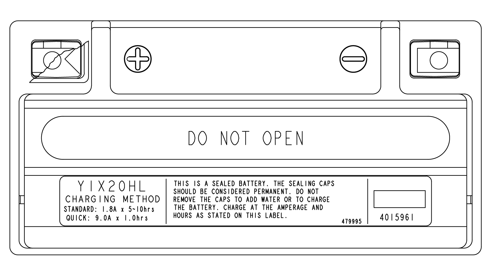
This Emissions Limited Warranty covers components if their failure
increases the vehicle’s regulated emissions, and it covers
components of systems if their only purpose is to control emissions.
Repairing or replacing other components not covered by this warranty
is the responsibility of the vehicle owner. This Emissions Limited
Warranty does not cover components if their failure does not increase
the vehicle’s regulated emissions.
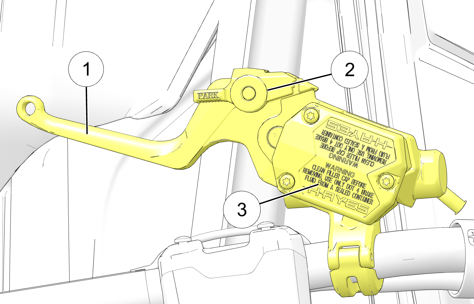
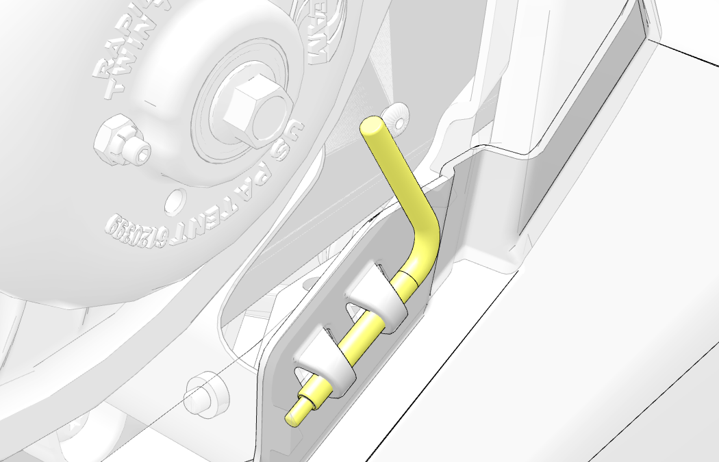
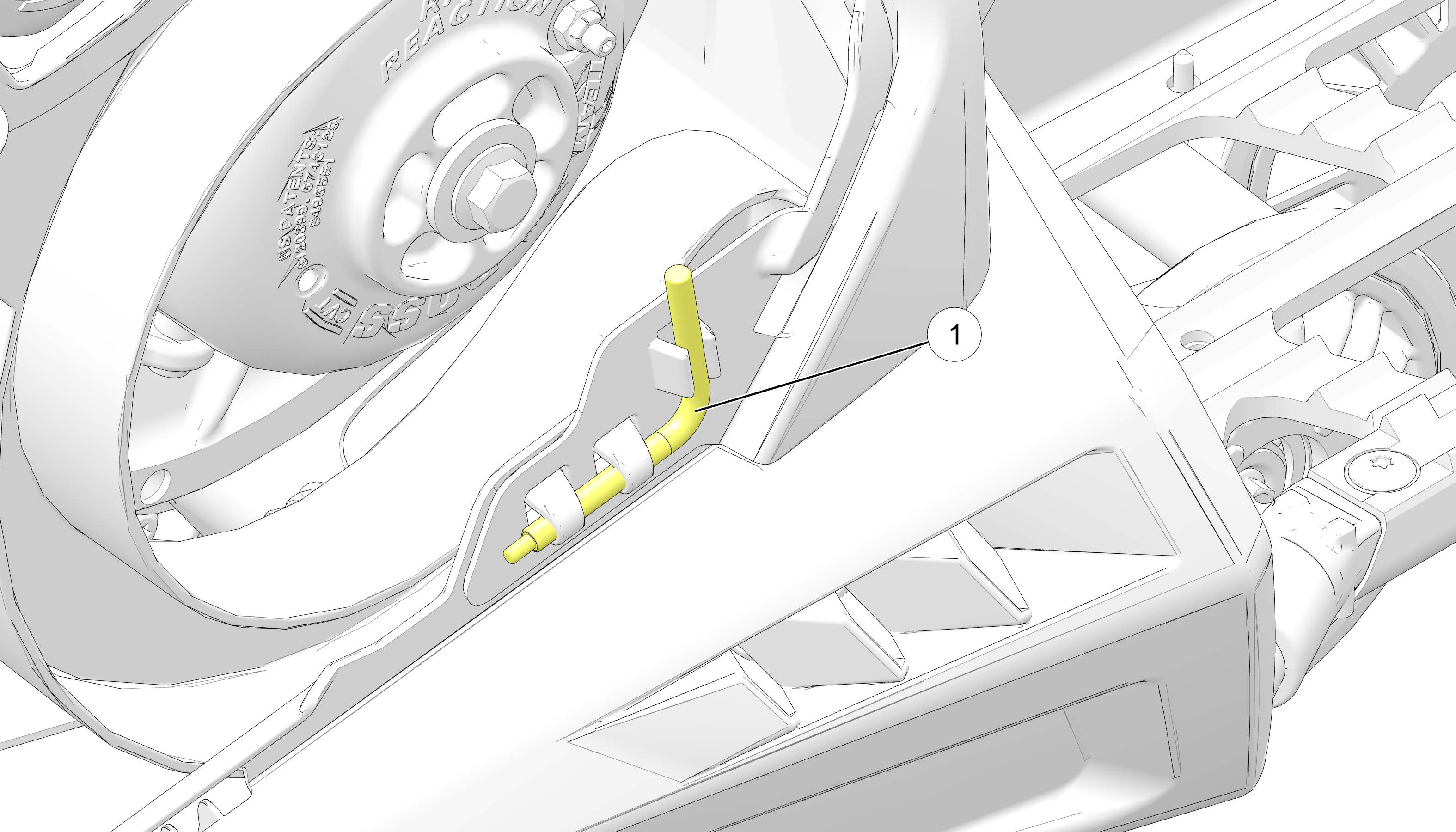
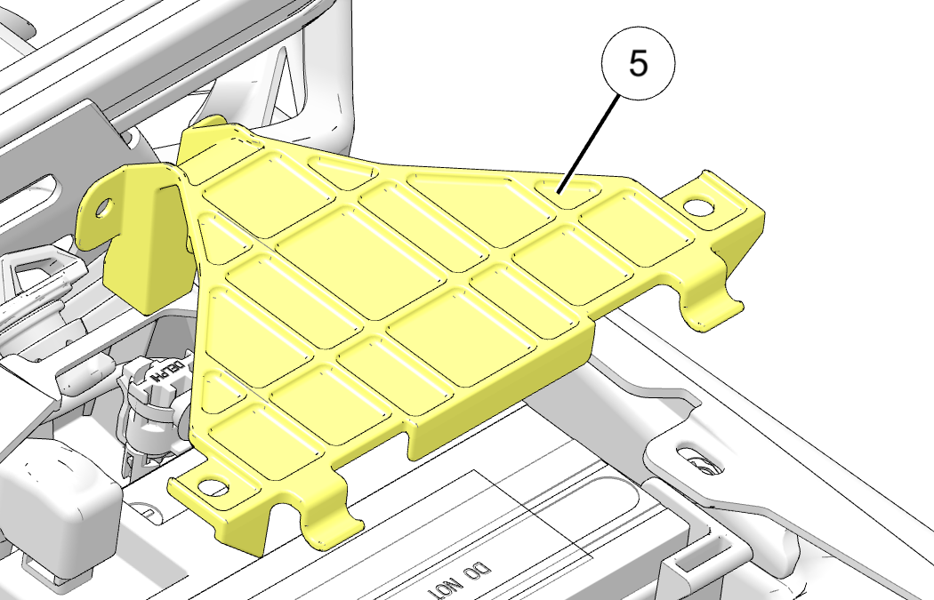
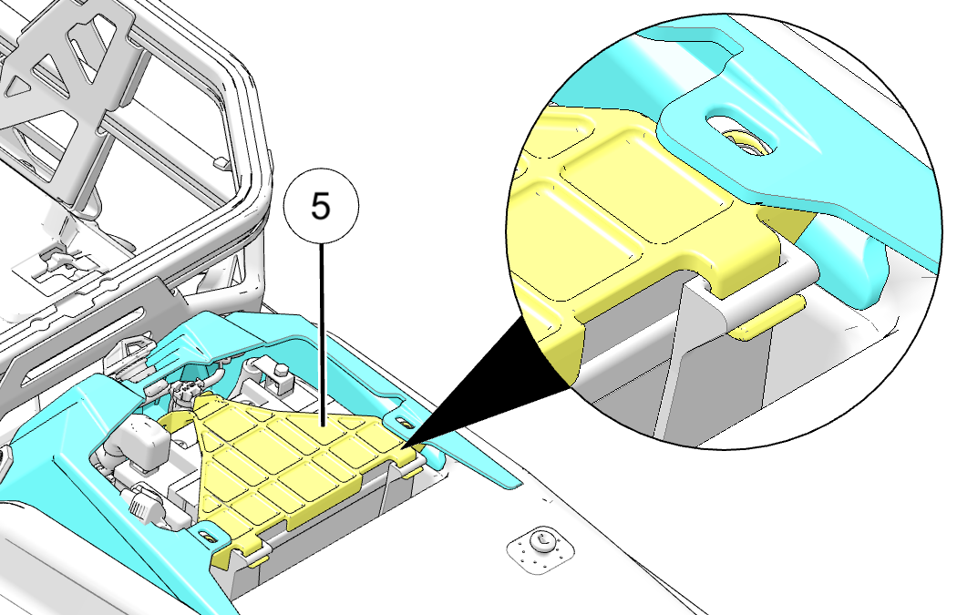
For exhaust emissions, emission-related components include any
engine parts related to the following systems:
-
Air-induction system
-
Fuel system
The following parts are also considered emission-related components
for exhaust emissions:
-
Sensors
-
Electronic control units
The following parts are considered emission-related components
for evaporative emissions:
-
Fuel Tank
-
Fuel Cap
-
Fuel Line
-
Fuel Line Fittings
-
Clamps*
-
Pressure Relief Valves*
-
Control Valves*
-
Control Solenoids*
-
Electronic Controls*
-
Vacuum Control Diaphragms*
-
Control Cables*
-
Control Linkages*
-
Purge Valves
-
Vapor Hoses
-
Liquid/Vapor Separator
-
Carbon Canister
-
Canister Mounting Brackets
-
Carburetor Purge Port Connector
*As related to the evaporative emission control system.
The exclusive remedy for breach of this Limited Warranty shall
be, at the exclusive option of POLARIS, repair or replacement of any
defective materials, components or products. THE REMEDIES SET FORTH
IN THIS LIMITED WARRANTY ARE THE ONLY REMEDIES AVAILABLE TO ANY PERSON
FOR BREACH OF THIS WARRANTY. POLARIS SHALL HAVE NO LIABILITY TO ANY
PERSON FOR INCIDENTAL, CONSEQUENTIAL OR SPECIAL DAMAGES OF ANY DESCRIPTION,WHETHER
ARISING OUT OF EXPRESS OR IMPLIED WARRANTY OR ANY OTHER CONTRACT,
NEGLIGENCE OR OTHER TORT OR OTHERWISE. THIS EXCLUSION OF CONSEQUENTIAL,
INCIDENTAL, AND SPECIAL DAMAGES IS INDEPENDENT FROM AND SHALL SURVIVE
ANY FINDING THAT THE EXCLUSIVE REMEDY FAILED OF ITS ESSENTIAL PURPOSE.
ALL IMPLIED WARRANTIES (INCLUDING BUT NOT LIMITED TO ANY IMPLIED
WARRANTIES OF MERCHANTABILITY AND FITNESS FOR A PARTICULAR PURPOSE)
ARE LIMITED IN DURATION TO THE WARRANTY PERIOD DESCRIBED HEREIN. POLARIS
DISCLAIMS ALL EXPRESS WARRANTIES NOT STATED IN THIS WARRANTY. Some
states do not allow limitations on how long an implied warranty lasts,
so the above limitation may not apply if it is inconsistent with the
controlling state law.
This Limited Warranty excludes failures not caused by a defect
in material or workmanship. This Limited Warranty does not cover damage
due to accidents, abuse or improper handling, maintenance or use.
This Limited Warranty also does not cover damage to any engine as
a result of being structurally altered, or when the vehicle has been
used in racing competition. This Limited Warranty also does not cover
physical damage, corrosion or defects caused by fire, explosions or
other similar causes beyond the control of POLARIS.
Owners are responsible for performing the scheduled maintenance
identified in the owner’s manual. POLARIS may deny warranty
claims for failures that have been caused by the owner’s or
operator’s improper maintenance or use, by accidents for which
POLARIS has no responsibility, or by acts of God.
Any qualified repair shop or person may maintain, replace, or repair
the emission control devices or systems on your vehicle. POLARIS recommends
that you contact an authorized POLARIS dealer to perform any service
that may be necessary for your vehicle. POLARIS also recommends that
you use only POLARIS parts, however, equivalent parts may be used
for such service. It is a potential violation of the Clean Air Act
if a part supplied by an aftermarket parts manufacturer reduces the
effectiveness of the vehicle’s emission controls. Tampering
with emission controls is prohibited by federal law.
If you have any questions regarding your warranty rights and responsibilities,
please contact POLARIS Owner Connections:
United States & Canada: 1-800-POLARIS (1-800-765-2747) or visit
polaris.com.


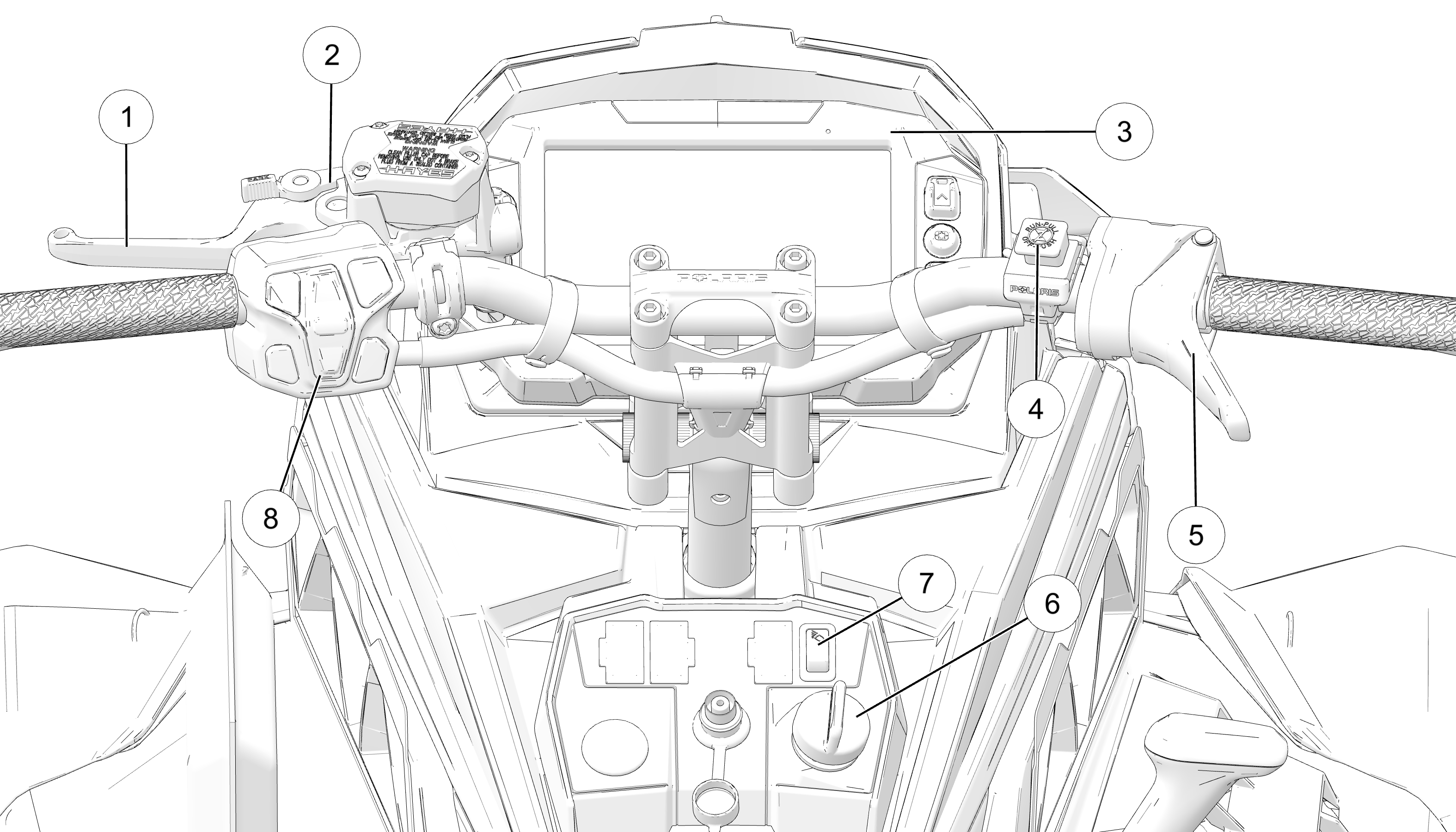
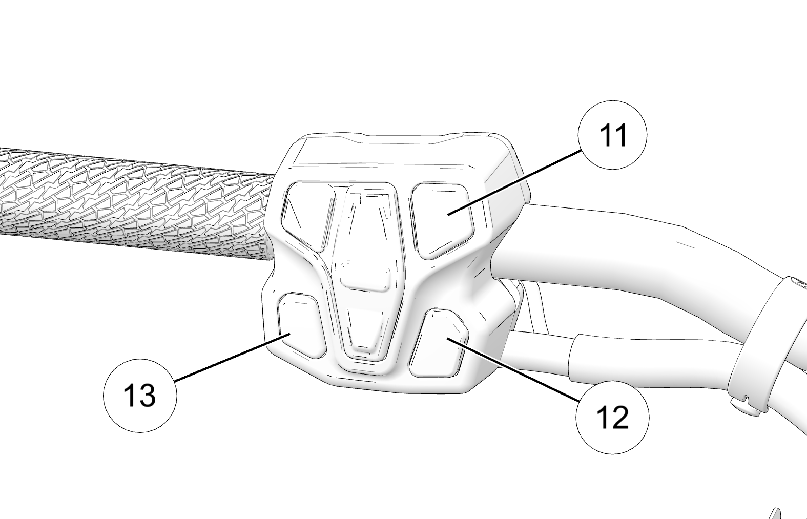
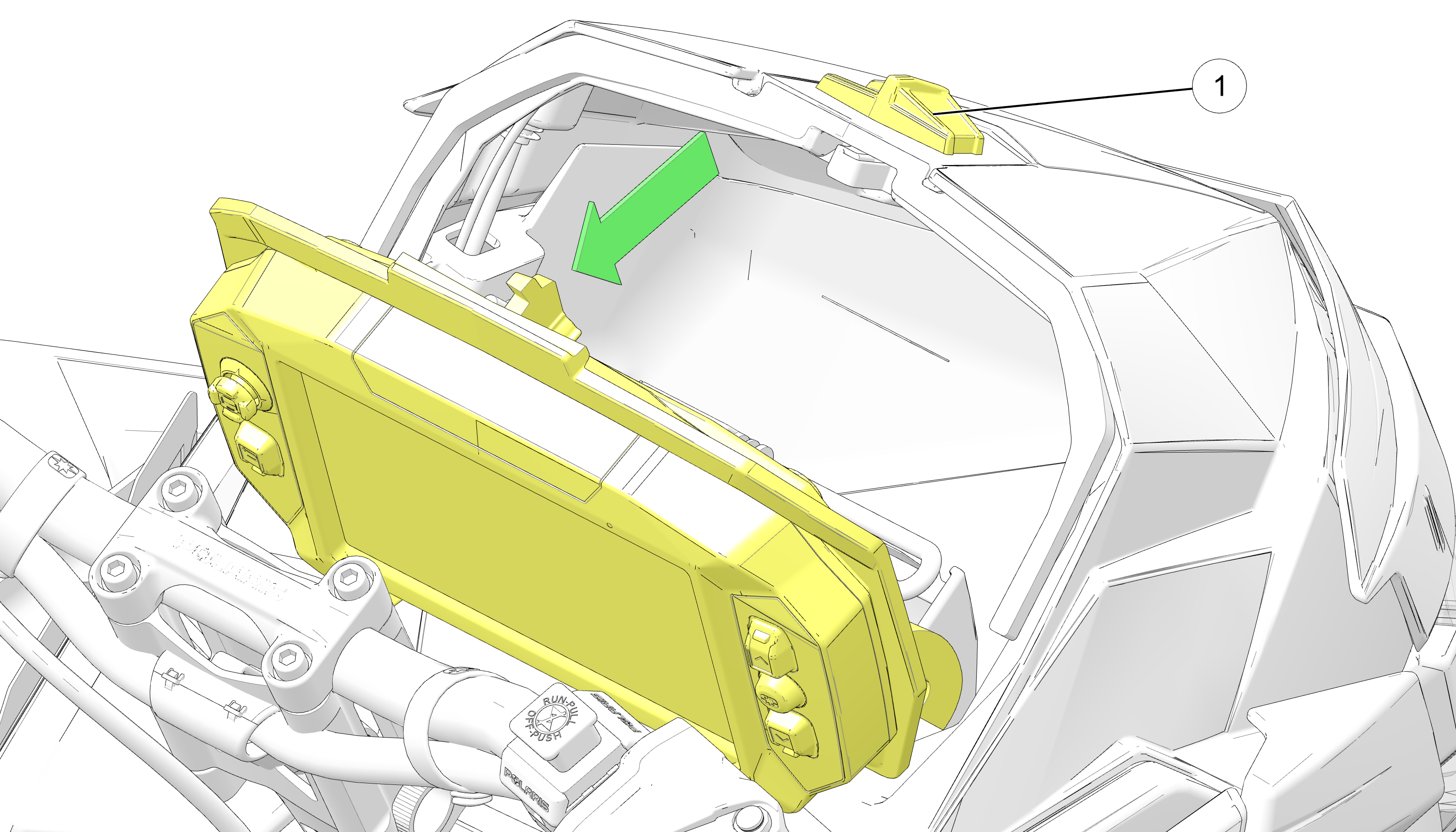
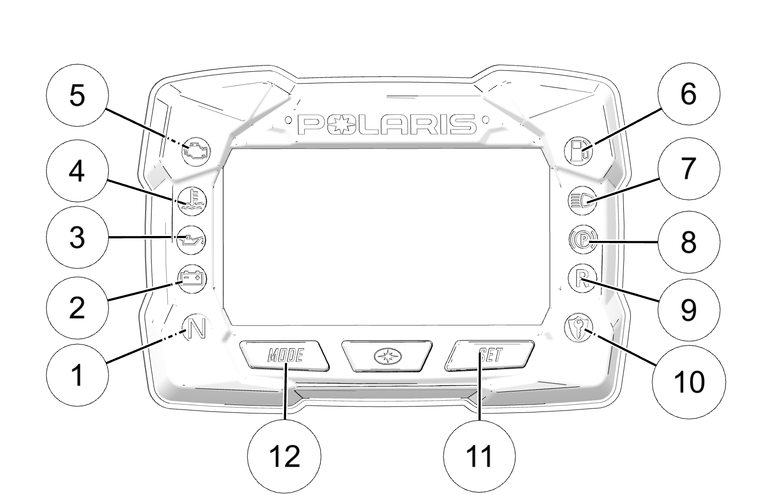


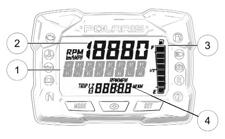
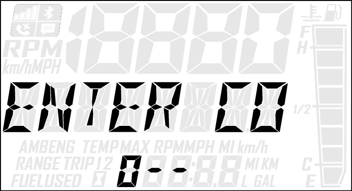
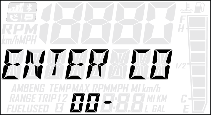
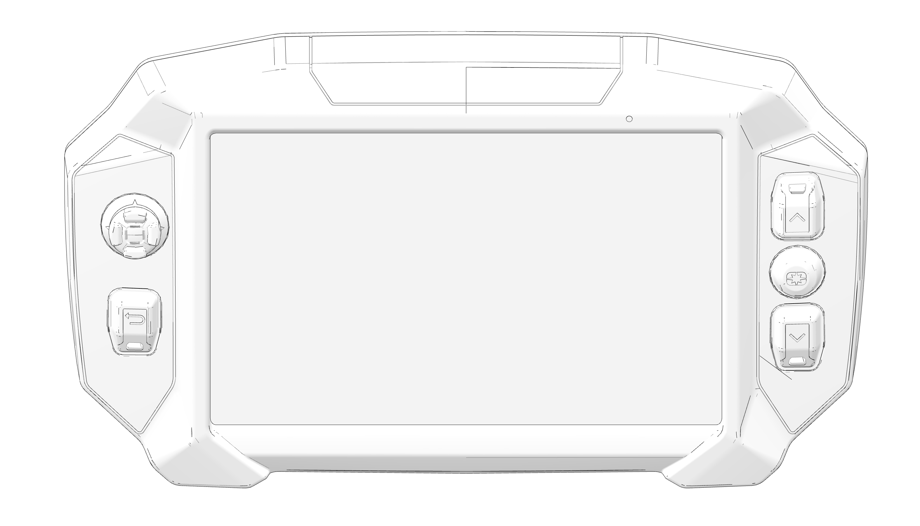
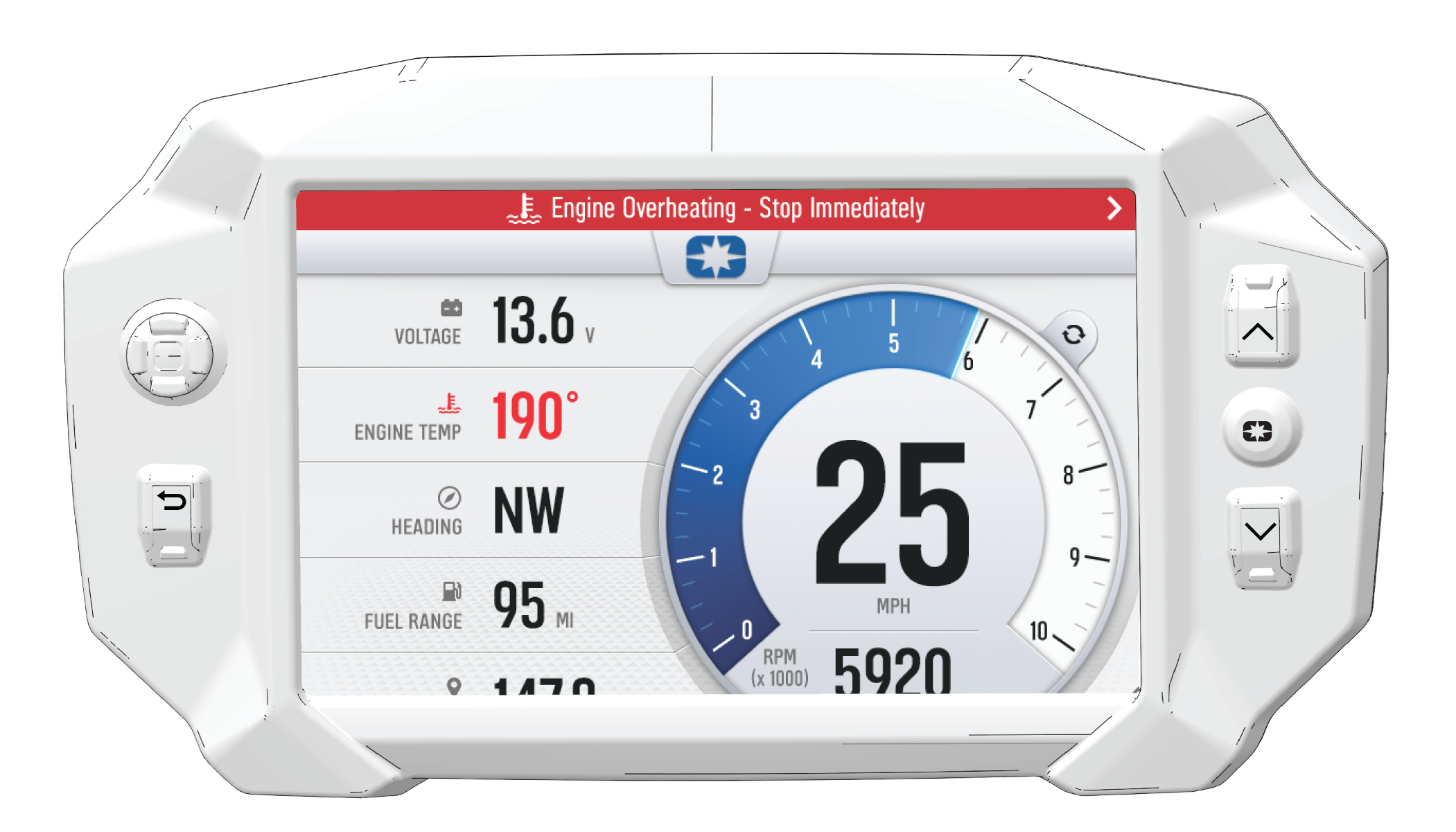
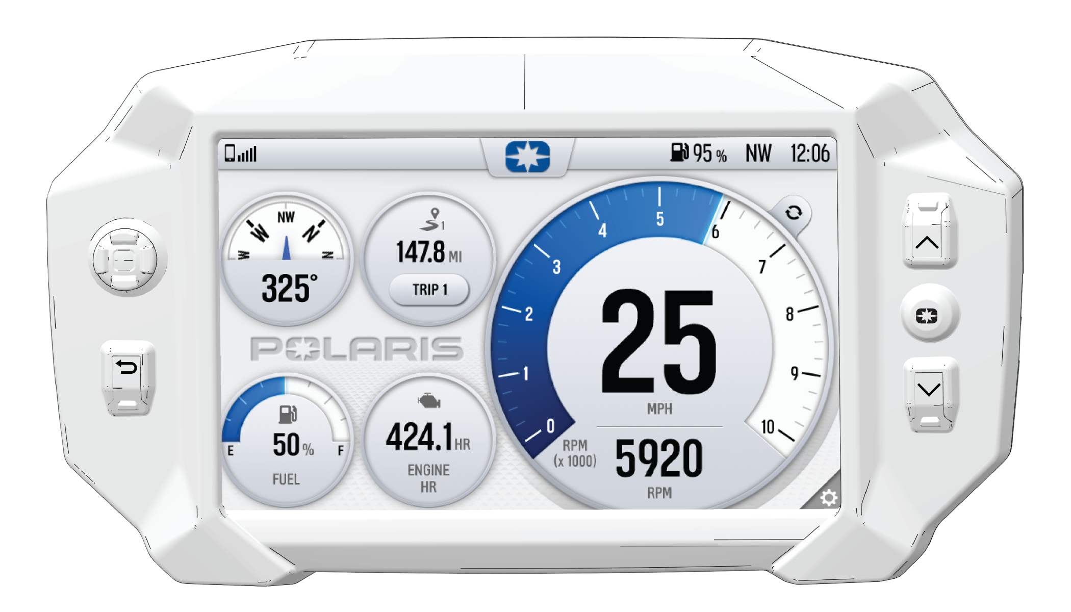
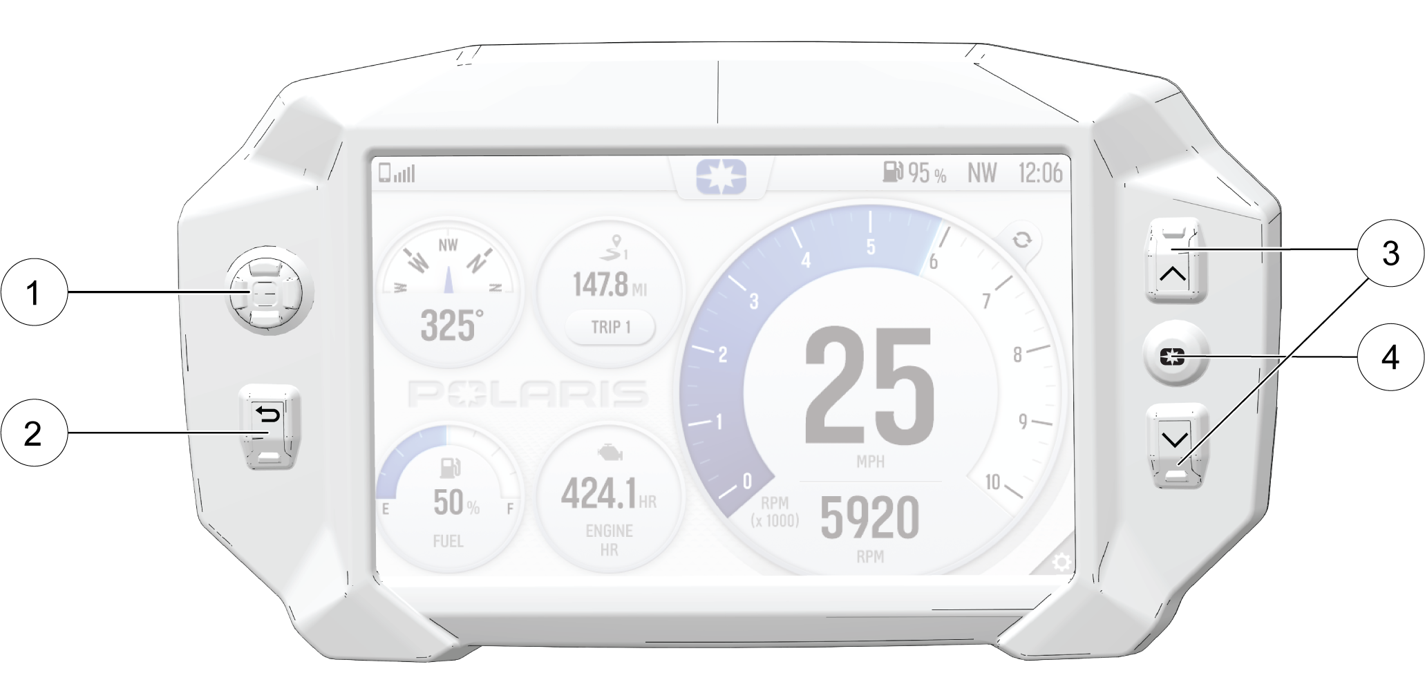
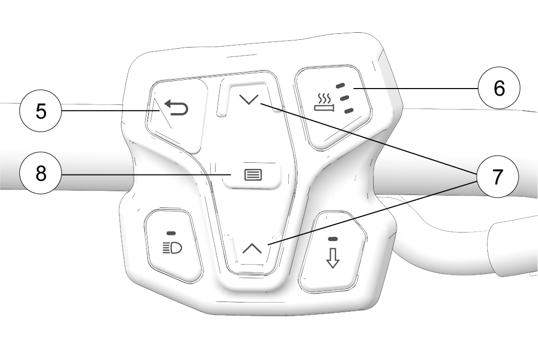
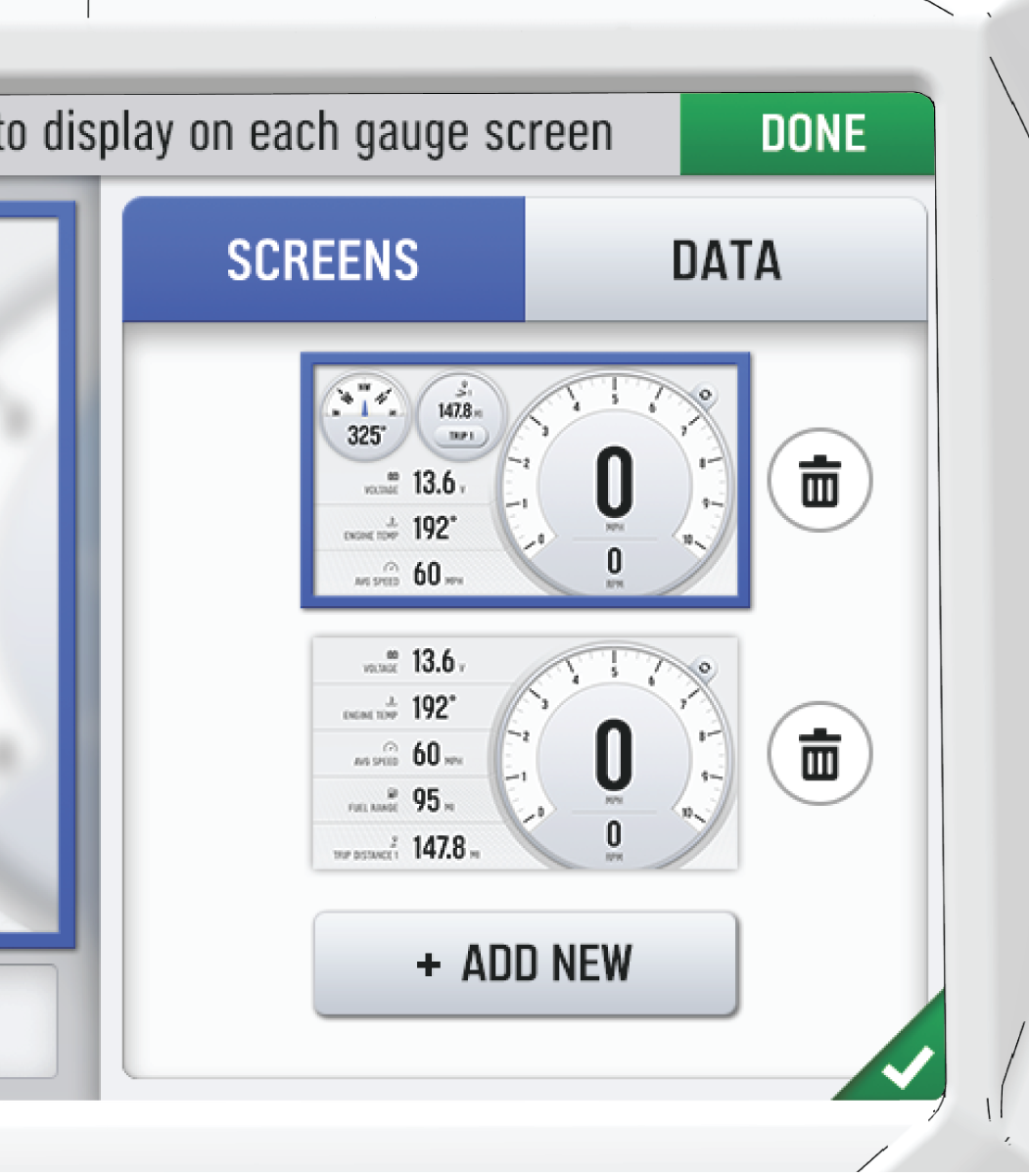
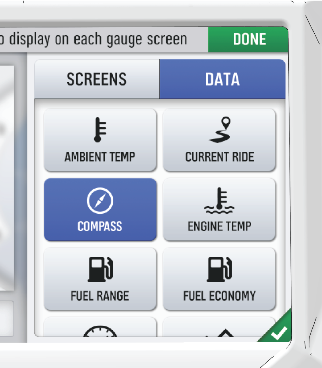
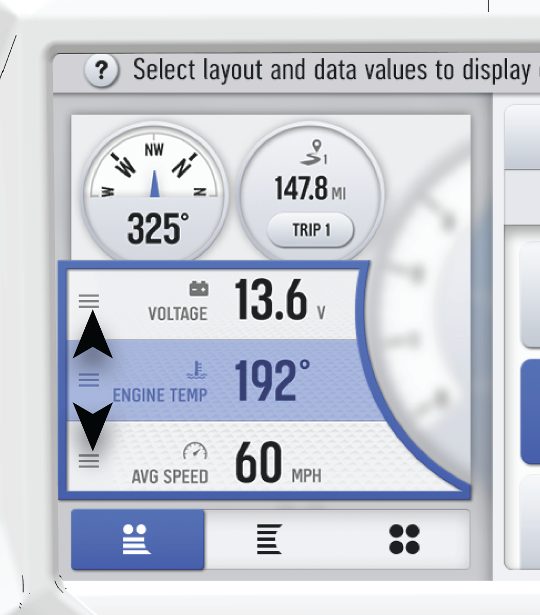
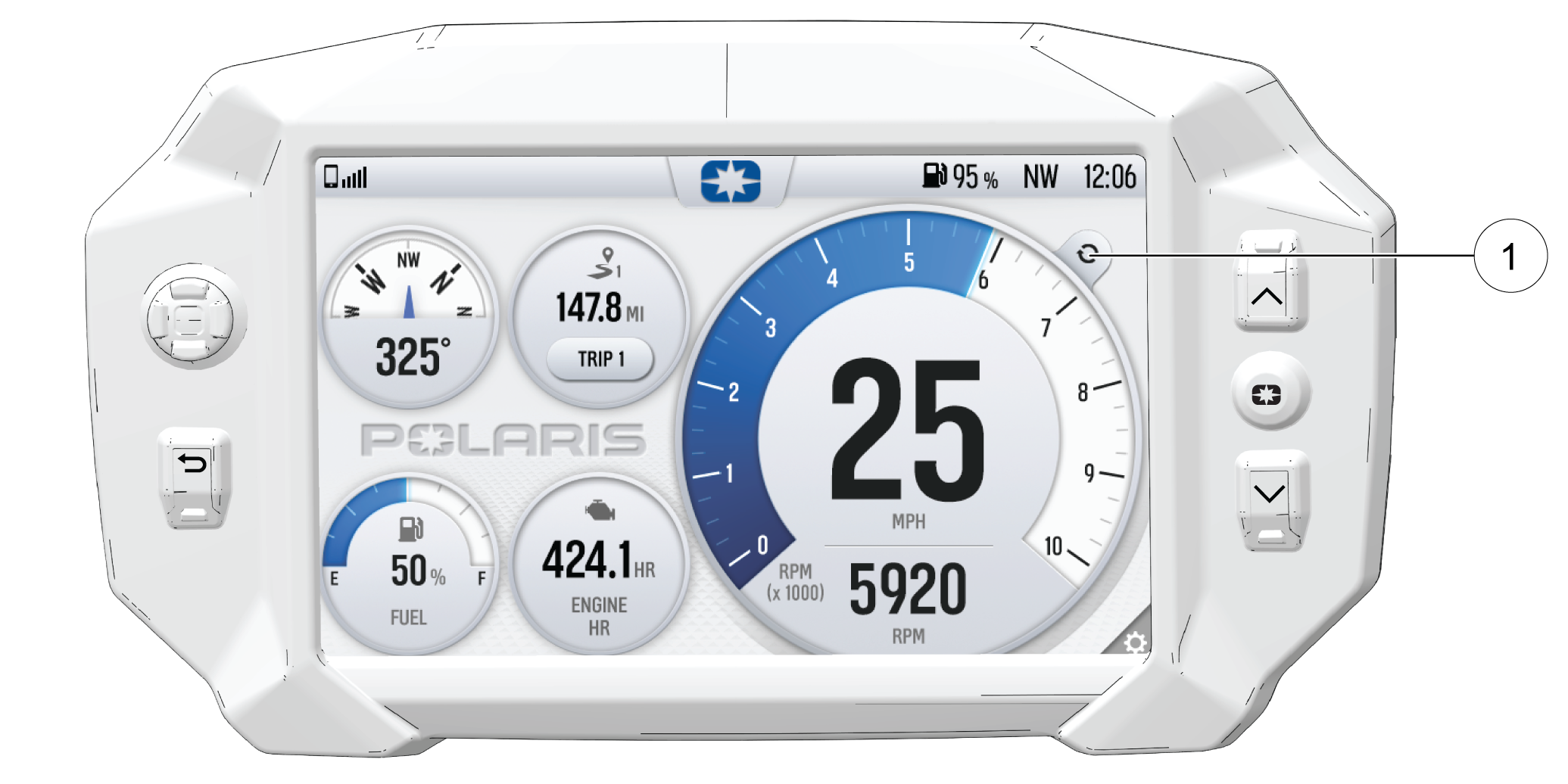
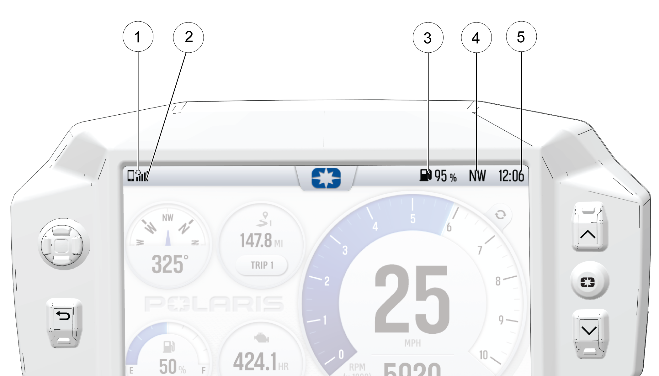
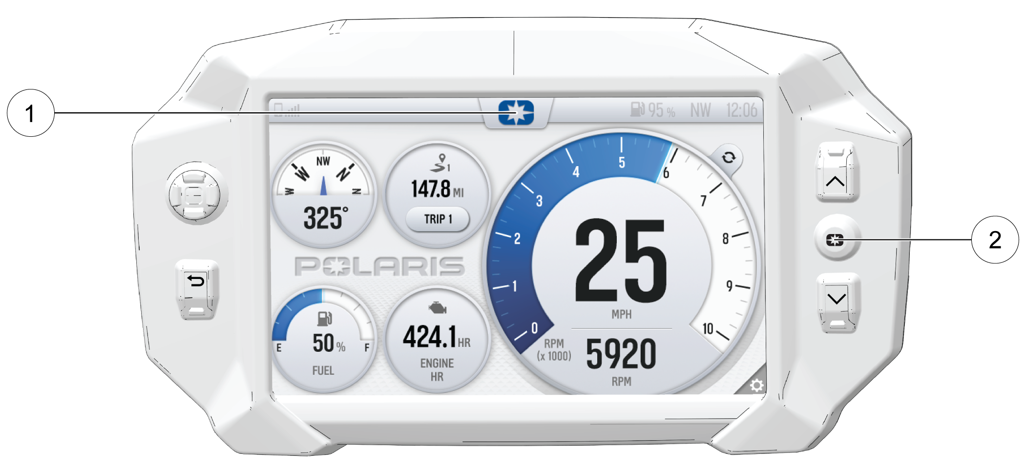
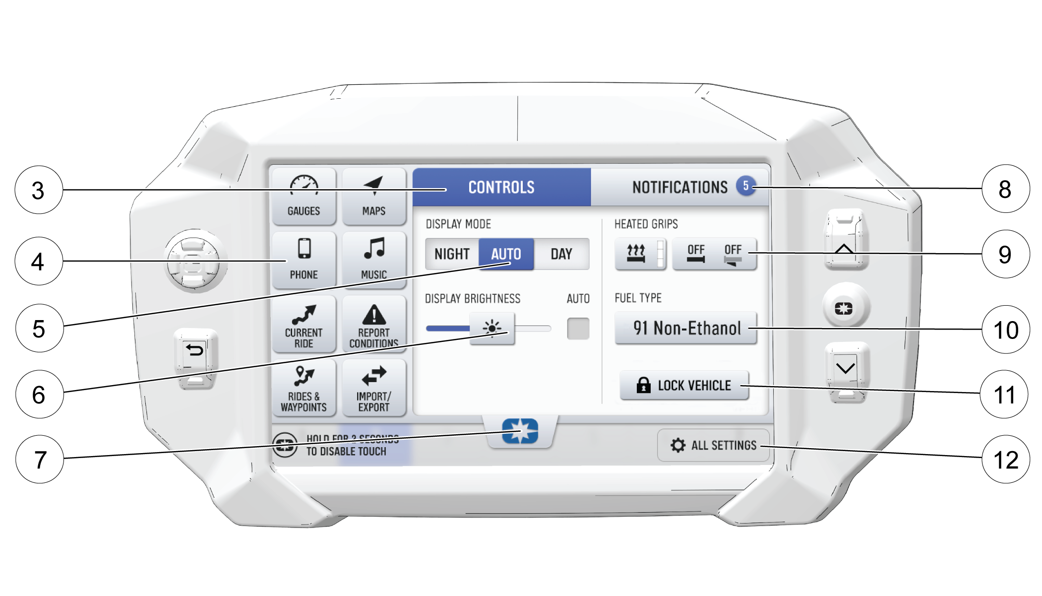
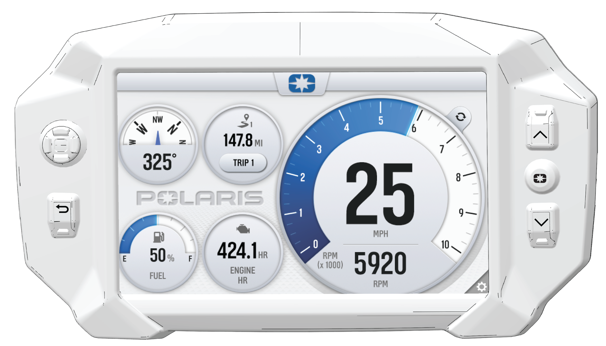
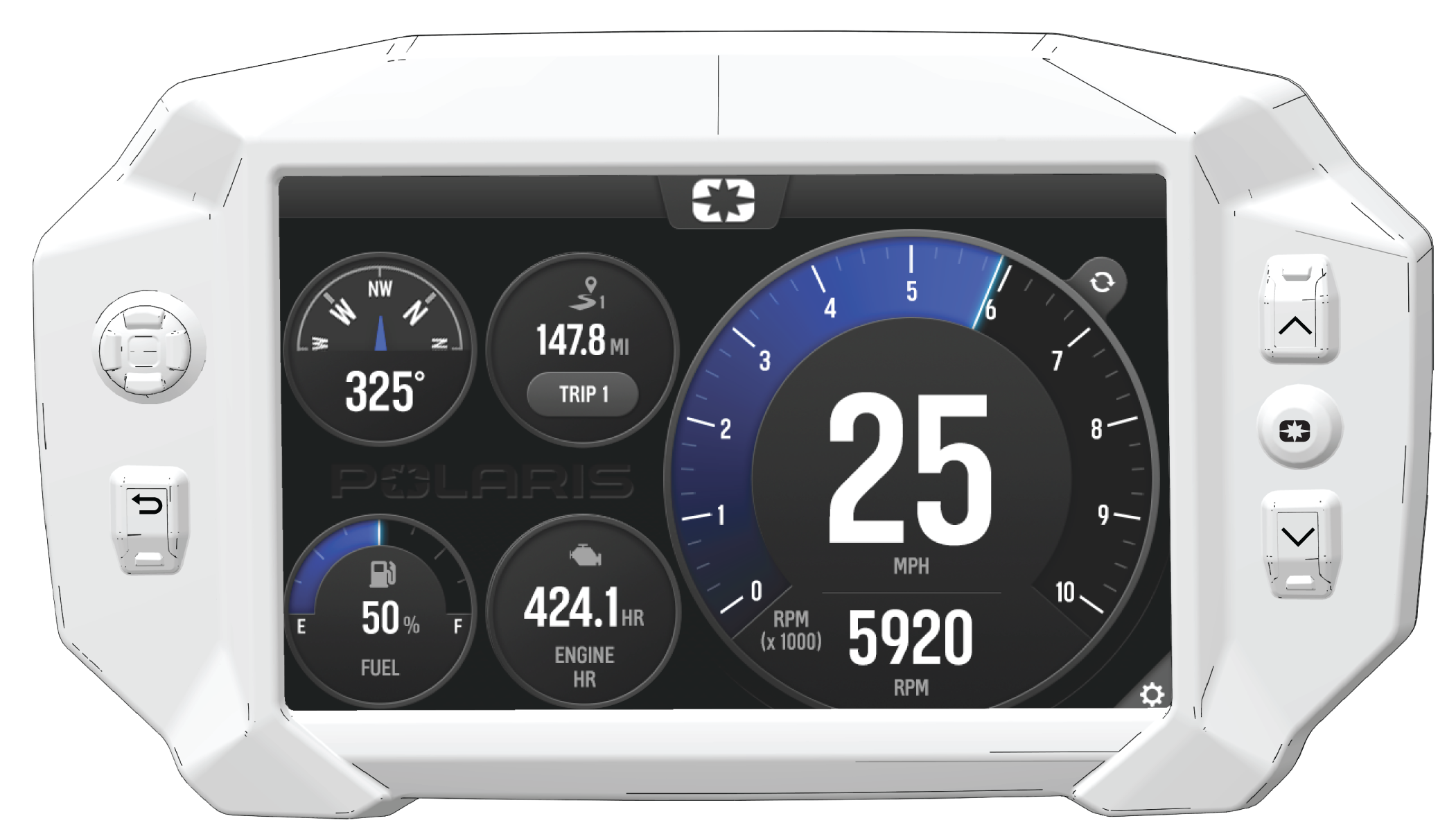
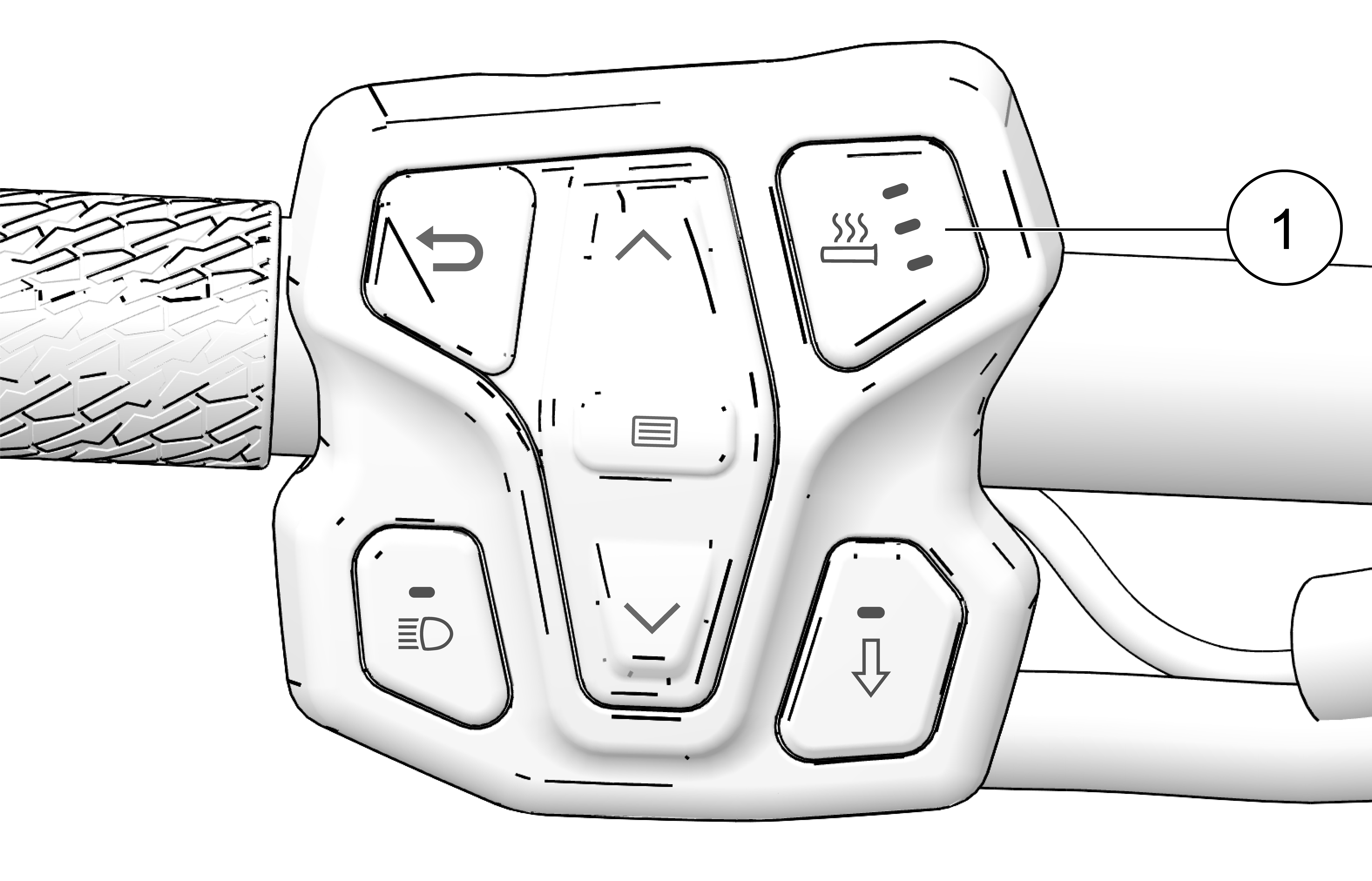
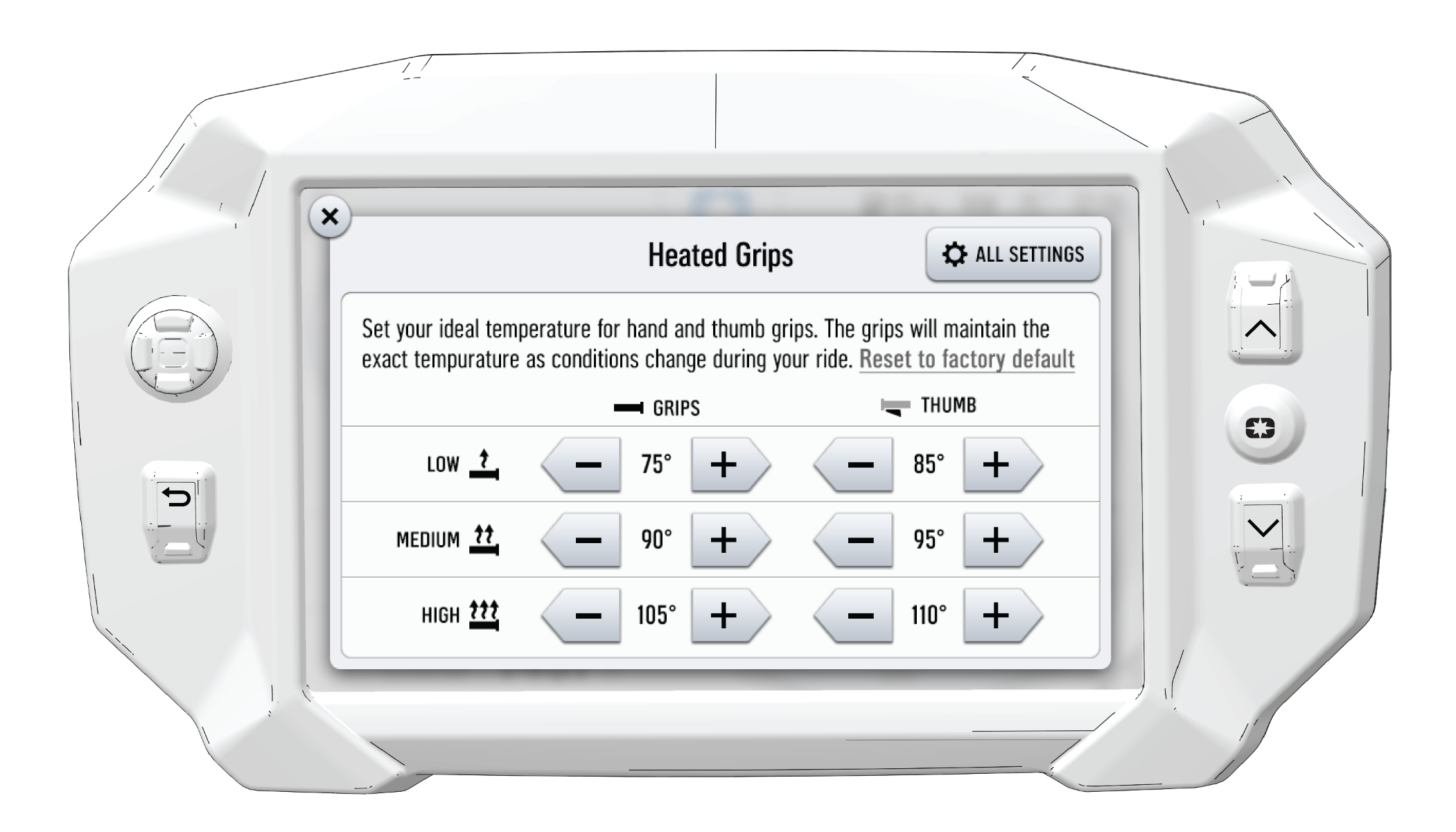
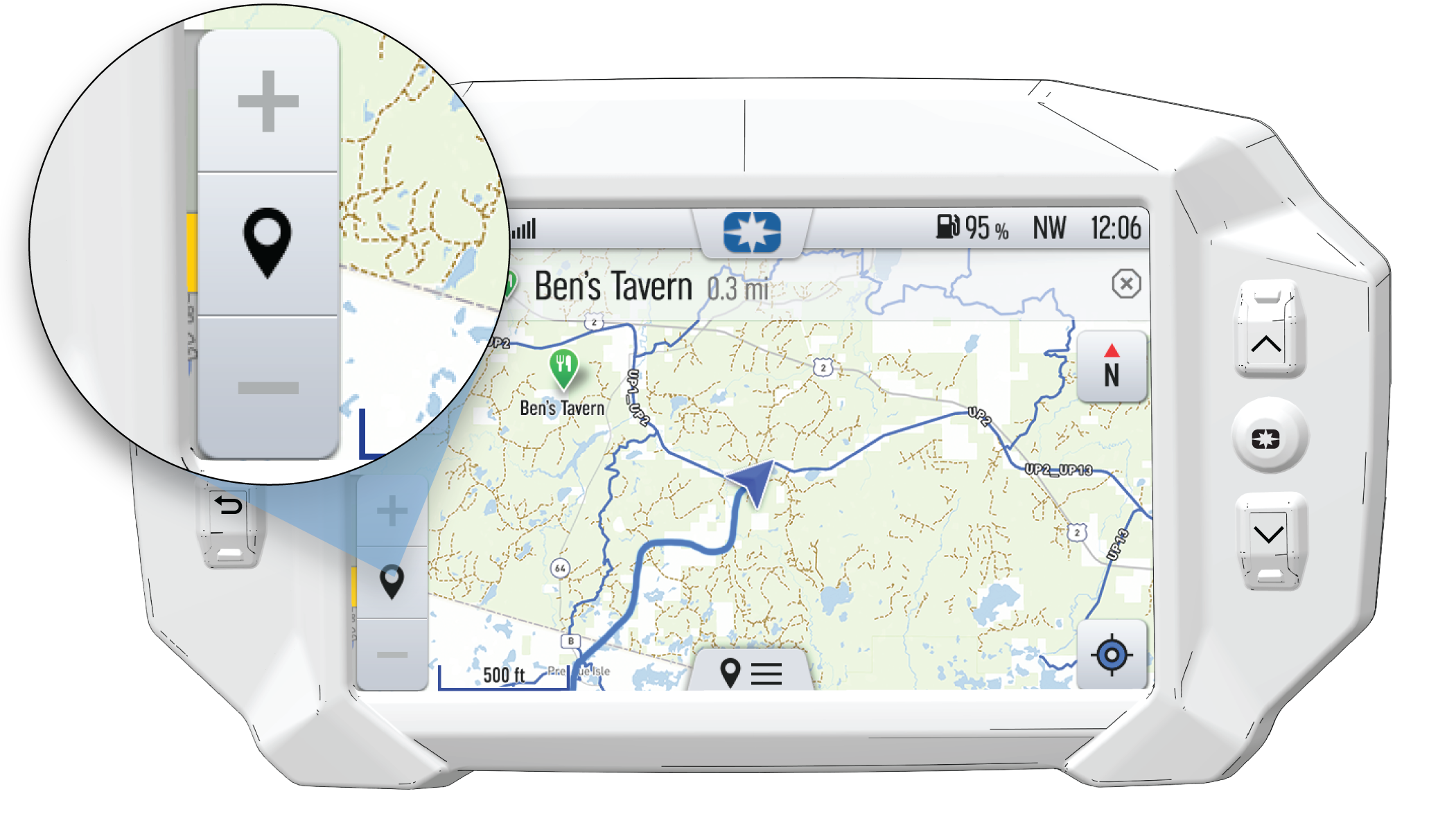
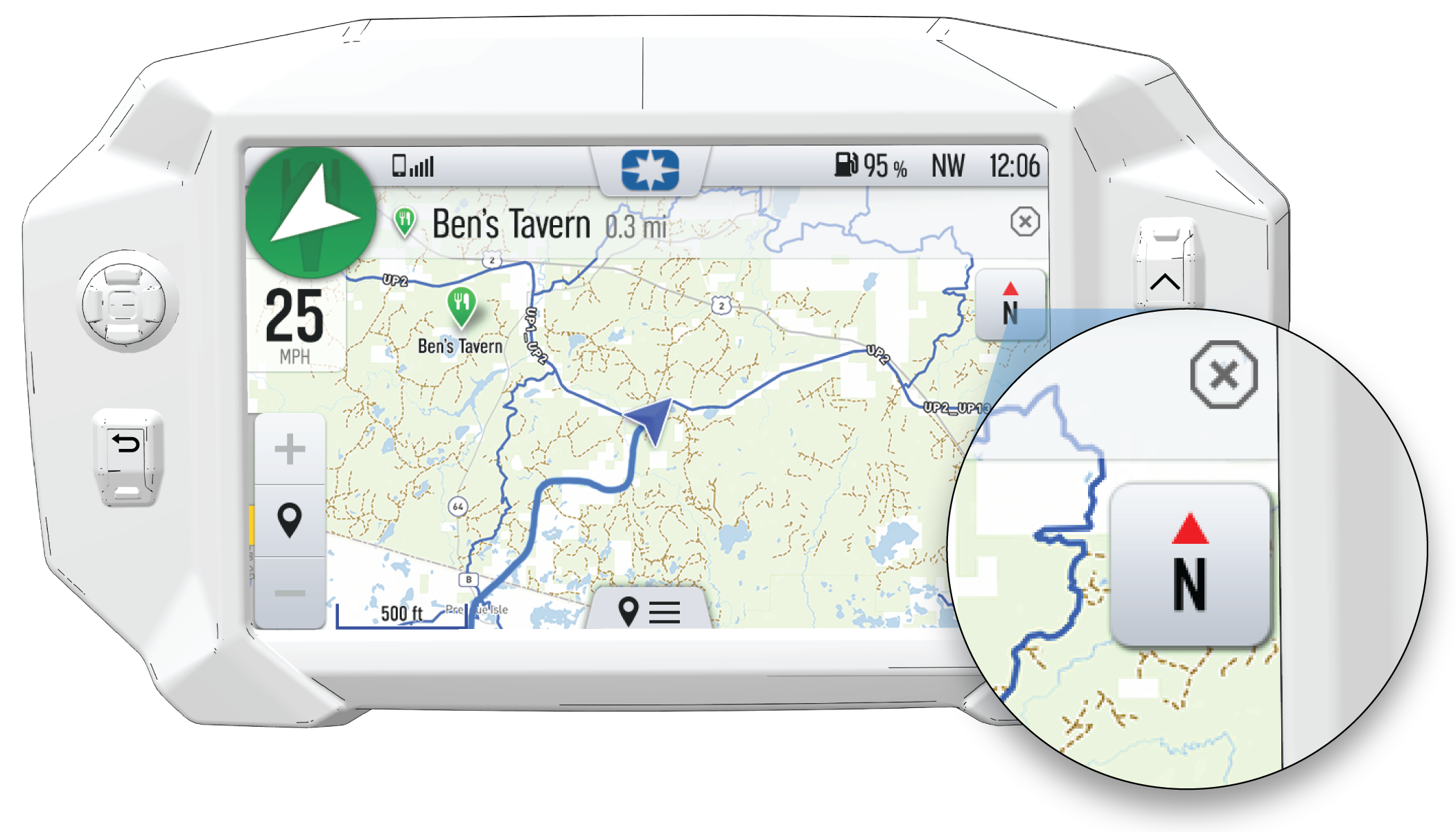
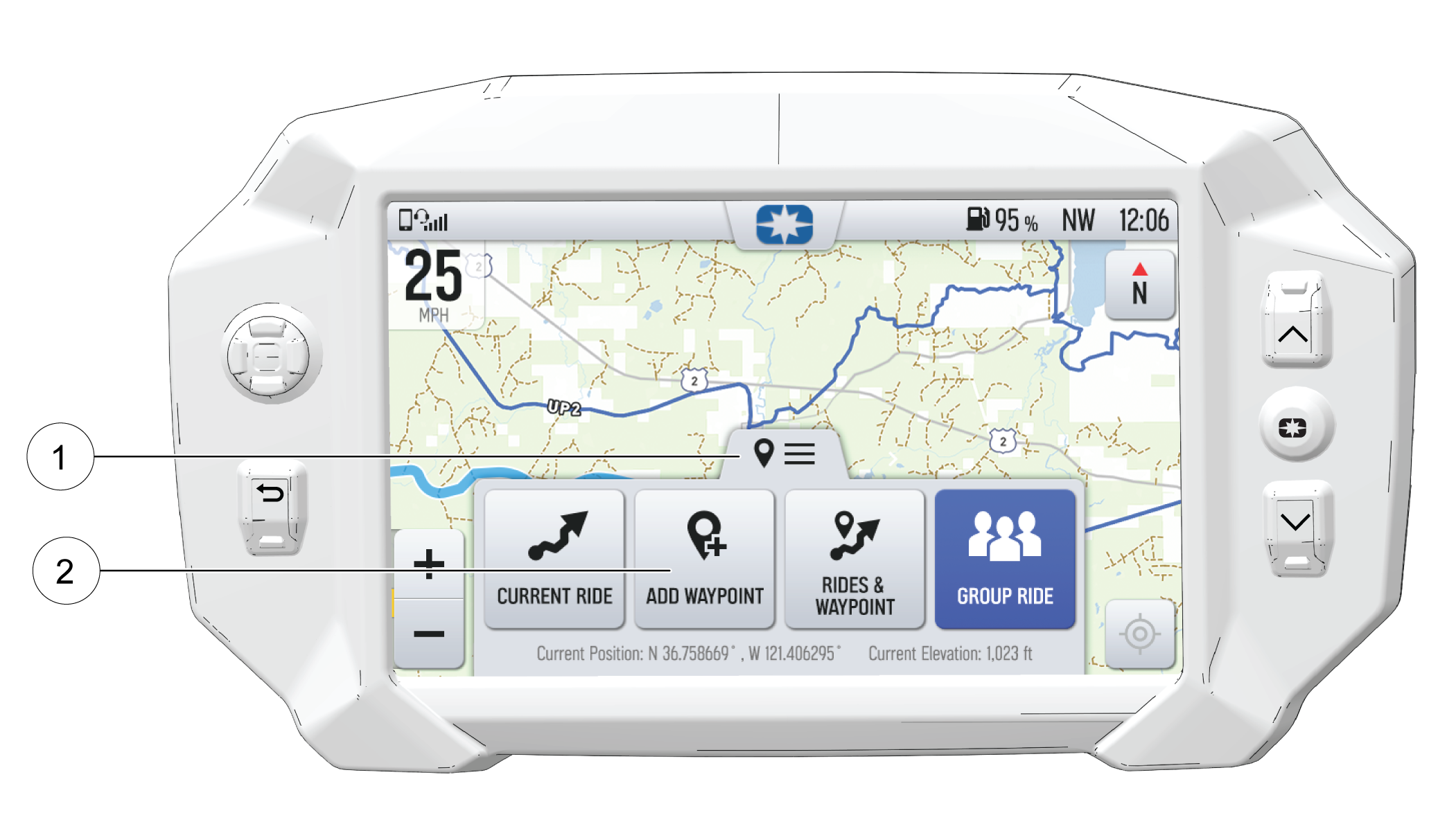
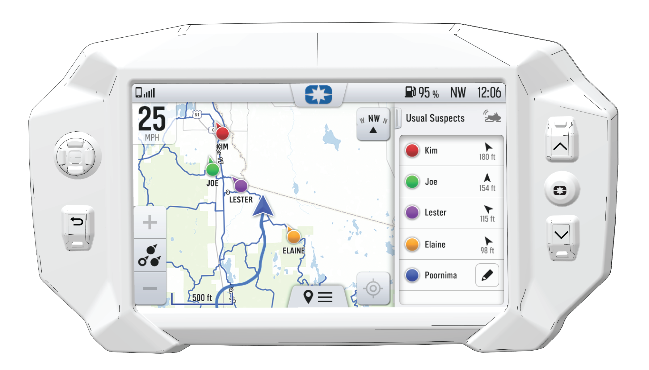
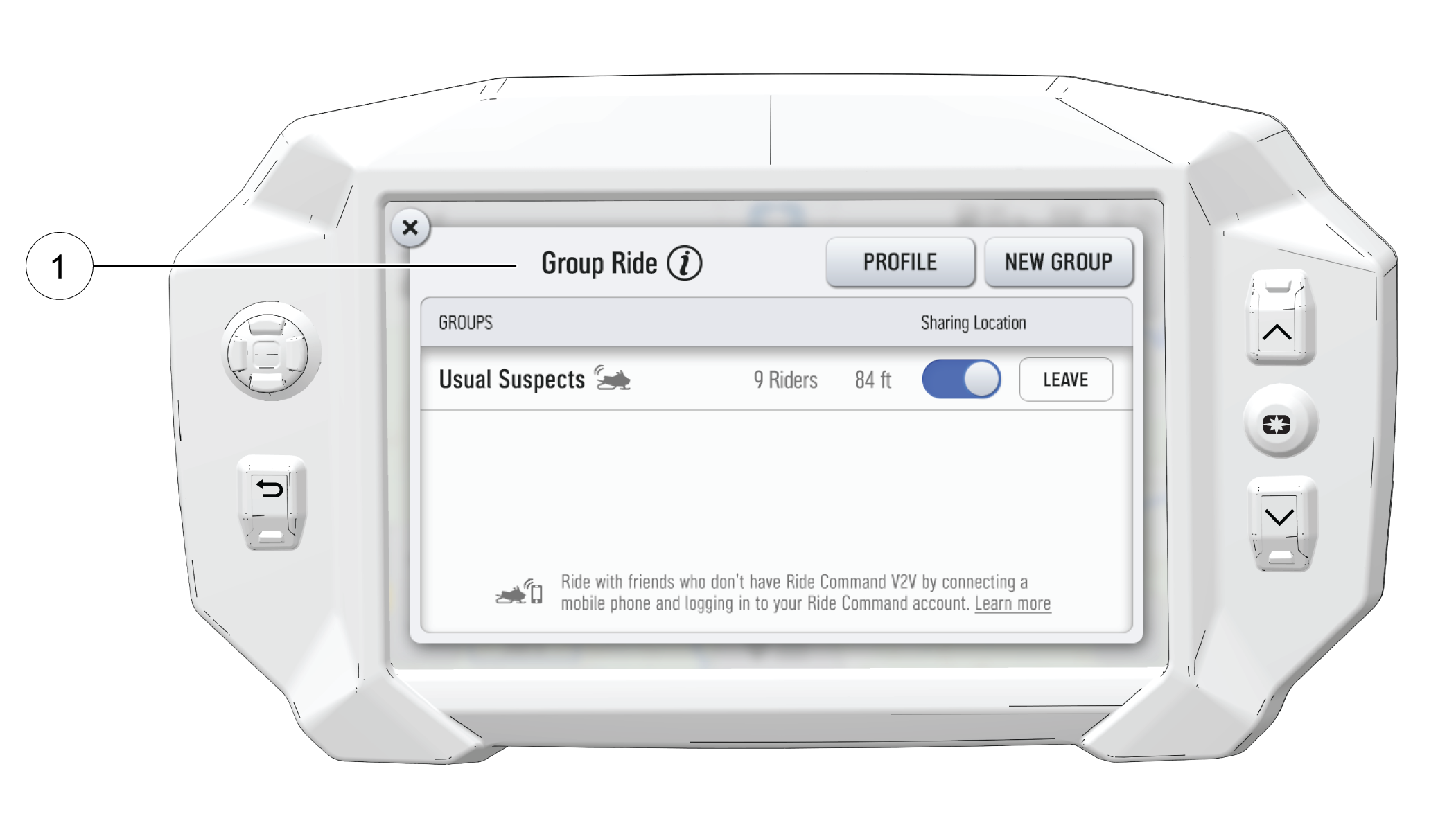
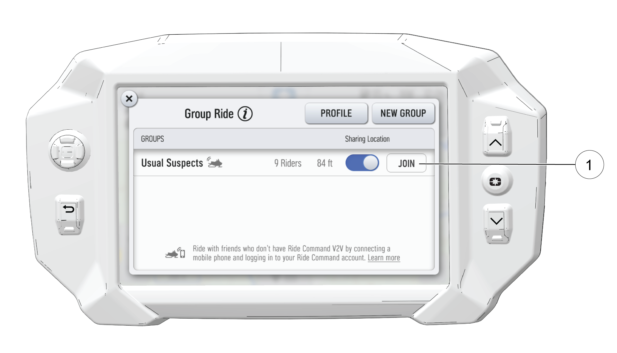
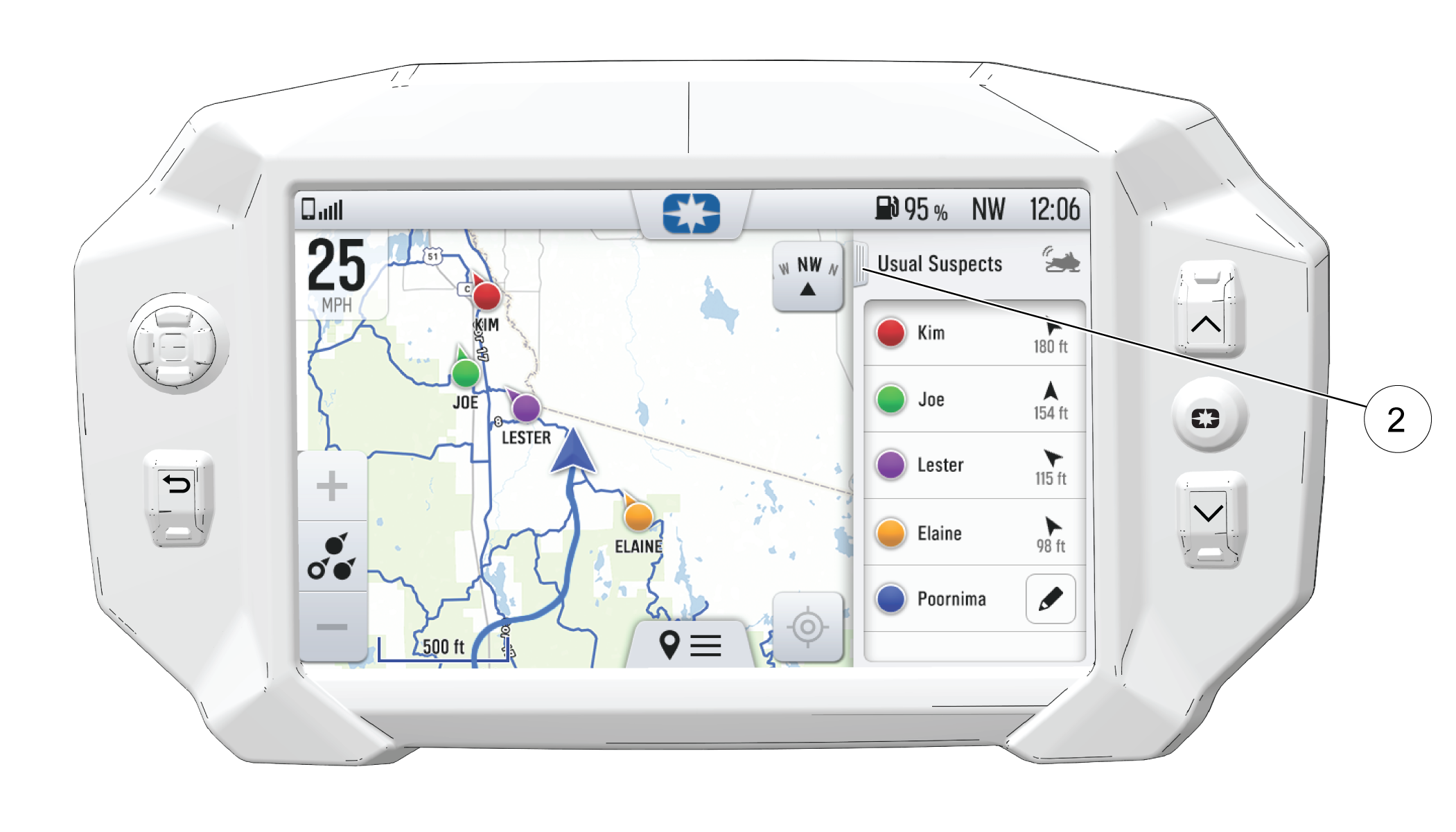
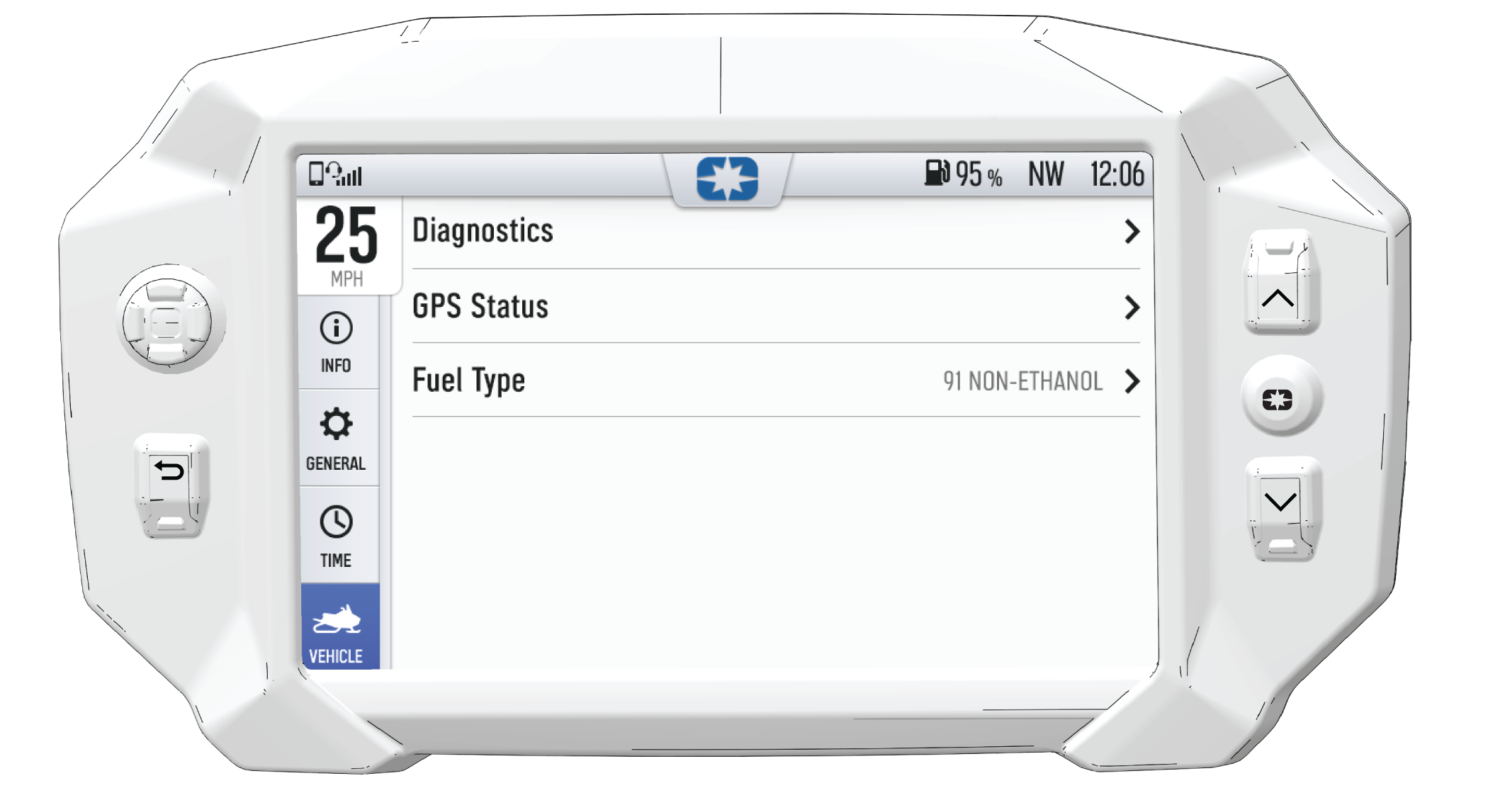
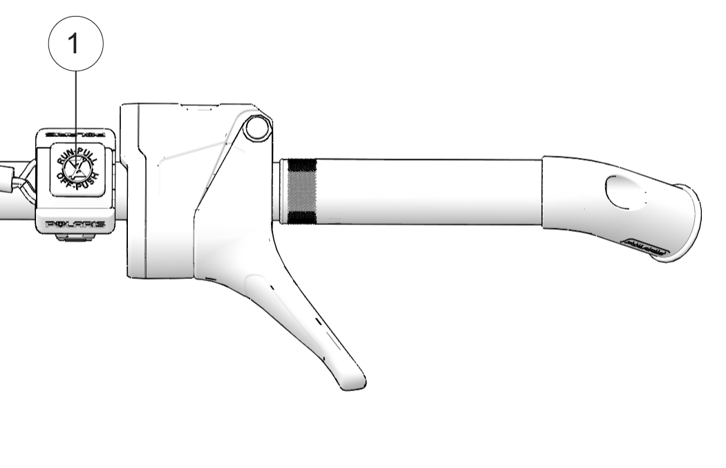
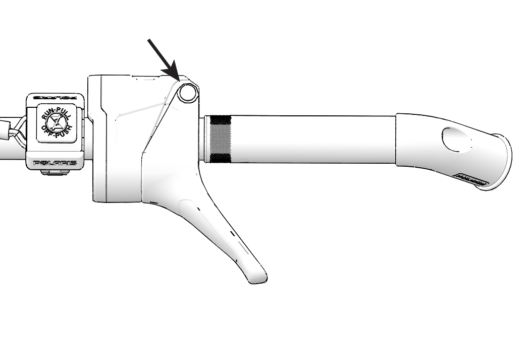
 button on the instrument cluster to enter the Options Menu.