Front Ski and Spindle Assembly
| SPINDLE SPACER APPLICATION | ||||
|
Left Side |
Right Side |
|||
|
RDCR Spec. |
Part # |
RDCR Spec. |
Part # |
|
|
Honda® |
18.03 mm |
5141390 |
25.4 mm |
5141389 |
|
Kawasaki® |
17.35 mm |
5141392 |
17.35 mm |
5141392 |
|
Yamaha® |
14.91 mm |
5141394 |
20.49 mm |
5141393 |
|
*Left and Right referenced from position of a rider sitting on the bike |
||||
-
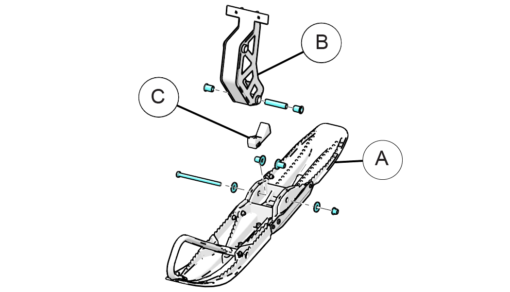
Locate the front ski A, spindle B, ski rubber C, and provided hardware.
-
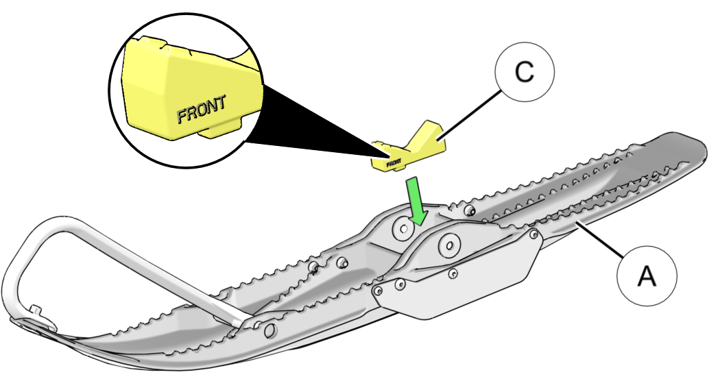
Place the Ski Rubber C on top of the center of the ski A with the indicated “Front” of the Ski Rubber towards the front tip of the Ski.
-
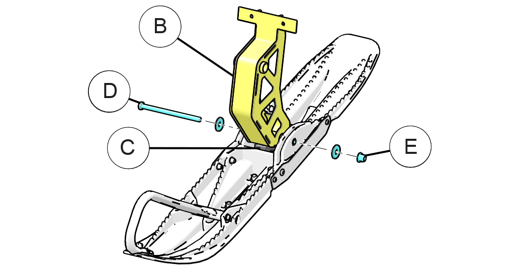
Place the lower portion of the Spindle B on top of the Ski Rubber C in the ski saddle as shown in the image below. Line up the bottom bolt hole and insert the M10 x 155 mm bolt D and install the nut E onto the bolt. Then torque to specification listed below.
TORQUESpindle Bolt:
33 ft-lbs (45 N·m)WARNINGFailure to torque fasteners as directed will adversely affect the steering system and may lead to severe injury or death.
-
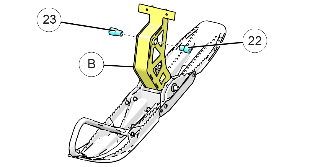
Insert front spindle reducers 22/23 onto the spindle B. Your motorcycle model’s Timbersled Ripper Install Kit will come with the appropriate spindle reducers/spacers for your motorcycle make and model. See the table entitled, Spindle Spacer Application, at beginning of this section for spindle reducer placement for your specific motorcycle model.
-
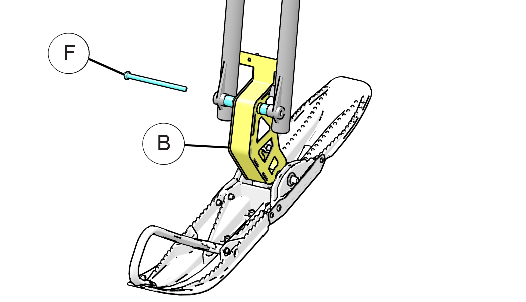
Use the existing front axle bolt F to attach the front spindle B to the forks A. DO NOT TIGHTEN the front axle bolt yet. The front axle bolt can be snug, but should not be fully tightened until you complete Step 6.
-
Using the composite fork clamp 14 (fork clamp halves are identical), place one half of the fork clamp in front of the fork tubes with the concave portions sitting around the face of the lower fork tube. Take the other half and mate it around the back side of the fork tubes between the fork tubes and the spindle backer plate B. Take the fork clamp washer plate 15 and place it over the face of the front fork clamp lining up the bolt holes of the washer plate15 with the clamp14. Using the two provided fork clamp bolts 16 supplied with your kit, insert each bolt through one of the two bolt holes (see image below). Apply the supplied locking nuts 17 and torque to specification listed below.
TORQUELocking Nuts:
15 ft-lbs (20 N·m)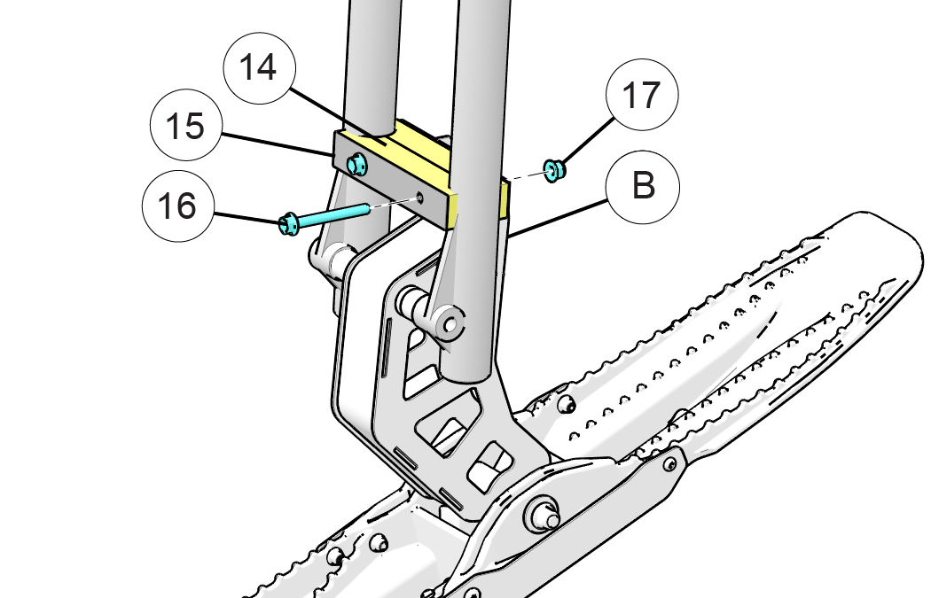
-
Tighten front axle bolt F.
IMPORTANTRefer to manufacturer’s specifications for the front axle bolt’s proper torque setting.
-
Check to ensure all previous steps are complete, and then move on to the Rear Cowling Assembly instructions.