Rear Timbersled Ripper Assembly
|
Left Side |
Right Side |
|||
|
Spacer Spec. |
Part # |
Spacer Spec. |
Part # |
|
|
Honda® |
0.80 mm |
5141218 |
6.87 mm |
5141219 |
|
Kawasaki® |
N/A |
N/A |
N/A |
N/A |
|
Yamaha® |
N/A |
N/A |
15 mm |
5141220 |
|
*Left and Right as positioned sitting on the bike |
||||
-
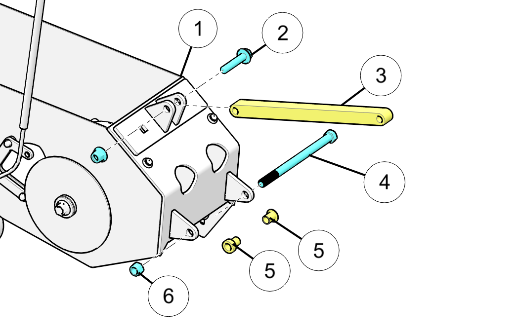
Position the Timbersled Ripper rear track assembly up to the rear swing arm bolt location on the bike. Some fit kits will require spacers 24/25 on one or either side of the frame, located between the Timbersled Ripper frame mount brackets and the bike’s swing-arm bolt bracket location. See the Swing Arm Spacer Application table at the beginning of this section for specific bike model spacers and locations.
NOTICEKawasaki® KLX models do not require any spacers. Honda® CRF models require left and right swing arm bolt spacers/reducers 24/25. Yamaha® TTR models require a single spacer positioned on the right side of the bike between the ripper frame bracket and the bike frame.
-
Slide provided 7/16” x 6-1/2” swing arm bolt 12 in from the left hand side of the bike and tighten lock nut 13 to listed torque specification.
TORQUE40 ft-lbs (54 N·m)
-
Bolt the lower portion of the strut rod 18 to the rear Timbersled Ripper assembly using the provided bolt 19 and lock nut 20. DO NOT TIGHTEN until after upper portion of strut rod has been bolted in place.
-
See note below before continuing.
NOTICEKAWASAKI® MODELS ONLY: Skip Step 4 below and complete Steps 5 and 6.
For Honda® and Yamaha® models, continue with Step 4.
Bolt upper portion of the strut rod 18 into the bike’s upper shock bracket using the bike’s upper shock mount bolt or pin. For bikes using a bolt, torque to the bike manufacturer’s specifications. Once you have the upper portion of the strut rod in place, torque the lower portion of the strut rod to the specification listed below.
TORQUE45 ft-lbs (61 N·m)
NOTICEFor Honda® and Yamaha® models, continue to the Brake Line Assembly and Routing section.
-
See note below before continuing.
NOTICEThis step includes the upper strut rod installation and brake line routing for Kawasaki® models only.
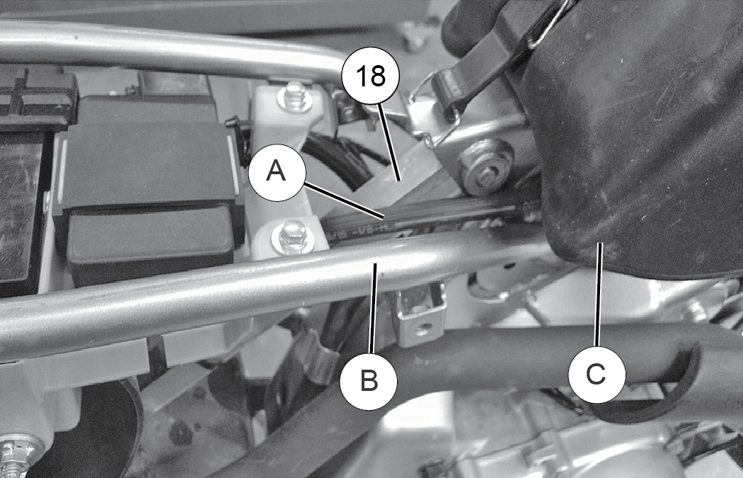
Once you’ve completed Step 3 and before you fasten the upper strut rod bolt, move the strut rod 18 up to provide enough clearance, feed the brake line A and master cylinder over top of the rear right sub-frame tubing B of the bike and under the gas tank C as seen in the image below. Now move the top of the strut rod 18 back down into position lining up the mounting holes.
 NOTICE
Some Kawasaki® models can use secondary bolt hole in the strut rod for lower ride height.
Finish bolting in place using the original upper strut rod bolt or pin and torque to your specific motorcycle manufacturer’s specifications. Once you have the upper portion of the strut rod in place, torque the lower portion of the strut rod to the specification listed below.
TORQUE45 ft-lbs (61 N·m)
-
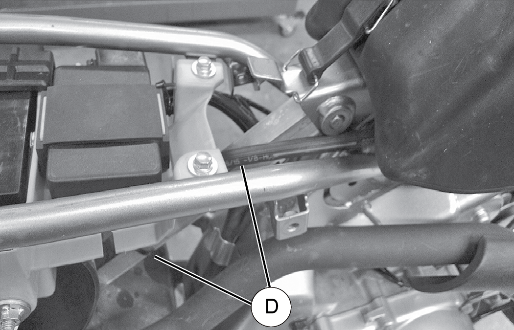
Keeping all of the slack out of the brake line, fasten the brake line to the top and the bottom of the strut rod with provided cable ties in the locations D indicated in the image below.
 WARNING
When routing brake lines, it is critical that you keep all brake lines away from any surfaces, such as engine or exhaust, that can become hot while operating the vehicle. Failure to comply will adversely affect the vehicle’s brake system and may lead to severe injury or death.
-
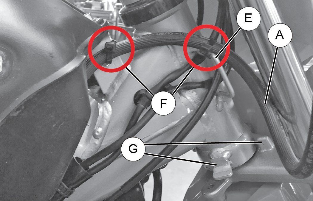
Run the brake line A forward under the bottom of the gas tank along the main frame of the bike towards the bike’s front neck-tube. Make sure there is a minimum of one inch of clearance between the brake line and the lower head set turning stop posts G to prevent the brake line from being pinched. Place another cable tie F around the brake line fastening it to the bike’s throttle cable keeper bracket E. The remaining brake line can free hang up to the master cylinder mounted on the right handle bar. Adjust the pitch of the brake lever, ensuring it is easily reached and easy to pull. Tighten the brake lever perch hand tight being careful to not strip the mounting perch threads. If needed, you can loop any remaining slack in the brake line in between the right fork tube upper and the neck-tube of the bike frame as seen in the photo below (Honda® model shown for reference).
 WARNING
When routing brake lines, make sure there is a minimum of one inch of clearance between the brake line A and the lower head set turning stop posts G to prevent the brake line from being pinched. Failure to comply will adversely affect the vehicle’s brake system and may lead to severe injury or death.
NOTICEFor Kawasaki® models, once you have completed Step 7, continue to the Drive Chain and Sprocket Assembly section.